The Effect of Connections on the global response of built-up cold-formed steel beams with corrugated webs
Ioan Both
1,*

,
Florin Bodea
1
,
Viorel Ungureanu
1,2
*Correspondence to:
Ioan Both, Department of Steel Structures and Structural Mechanics, Politehnica University of Timisoara, 300006, Timisoara, Romania.
E-mail: ioan.both@upt.ro
J Build Des Environ. 2023;1:6461. 10.37155/2811-0730-0101-2
Received: June 24, 2022Accepted: September 16, 2022Published: November 10, 2022
Abstract
The objective of this paper is to quantify the slippage and rotation in the connections of a double fixed corrugated web beam. Two types of connections between the component parts of the built-up beam were used, i.e. Metal Inert Gas (MIG) brazing and spot welding, which offer different rigidities and bearing capacities for the built-up beams. Experimental tests were conducted on three MIG brazed and two spot welded specimens, respectively. The test setup consisted of a six-point bending configuration which is equivalent to a uniform distributed load applied to the beam. The load was applied from a 500 kN actuator through a leverage system that allowed the distribution of the force. An out-of-plane structure prevented the beam from lateral torsional buckling. The testing exhibited relatively large slippage and deformation in the bolted connections and in the supporting device, respectively. However, the high rigidity of the beam maintained the mid-span deflection in the serviceability limit state limits. The built-up corrugated web beams made of cold-formed steel profiles represent an efficient and suitable structural solution for buildings. Nevertheless, experimental research due to inevitable slippage and the endplate deformation must be performed to characterize the connection.
Keywords
Built-up corrugated web beams, MIG brazing, spot welding, semi-rigid connection, shear buckling, deflection
1. Introduction
Built-up corrugated web beams (CWB) are increasingly used in the mainframe of single-storey buildings or as secondary beams in multi-storey structures, due to the lower material consumption with an increased buckling resistance. For these elements, the flanges provide the main bending resistance, with a small contribution of the sinusoidal corrugated web that offers shearing capacity. The design of corrugated web beams is included in Annex D of EN 1993-1-5[1] together with the specific aspects covered by EN 1993-1-1[2] and EN 1993-1-3[3].
Starting from the traditional welding applied to connect the thin web to the thick flat steel flange[4], the technological solution of corrugated web beams was enlarged by using cold-formed steel which offers a variety of connections between the component parts e.g. screws, bolts, spot-weld, Metal Inert Gas (MIG) brazing, clinching.
Results on the study of built-up beam, consisting of trapezoidal corrugated web and parallel flanges made of thin-walled cold-formed steel lipped channel sections can be found in Dubina et al.[5,6], in which the connections between the flanges and the web were done by self-drilling screws. This solution still demands an increased time for manufacturing. Also the rigidity of the beams is less satisfactory as the interest for the influence of this characteristic represents an attractive research topic[7].
An improved solution due to the lower material consumption, less screws and bolts, but with increased rigidity can be found in the shape of the built-up corrugated web beams of cold-formed elements which uses spot welding[8]. Nevertheless, due to discrete connections and high stress concentration, premature local buckling occurs, and the bearing capacity is decreased.
To avoid local buckling of the corrugations, MIG brazing connects the flange and the web on an increased length and distributes the local stress which appear in the case of discrete fasteners, leading to an increased rigidity and capacity of such beams[9].
In terms of analytical solutions, previous studies have demonstrated the basic assumption of corrugated web beams that the flanges take the stresses from bending moments[10], and have identified a corrugation-dependent failure mode[11].
The resistance spot weld can be described as two copper alloy electrodes which apply a compressive force and a high electric current, which locally heats the parts, by Joule-Lenz effect, in a very short time. Thus, the material between the electrodes, at the interface of the contact zone between sheets is melted under the form of melted nucleus and after the welding current has stopped, the materials solidify and the joint results, creating a welded spot. Briskham et al.[12] presented the advantages of spot weld in a comparative study on self-pierce riveting, resistance spot welding and spot friction joining, identifying the resistance spot welding as a more favorable option.
MIG brazing represents a welding technique at a temperature lower than the base material melting temperature such that thin steel sheets can work together under loading conditions. The shielding gases and the process parameters have a great influence on MIG brazed joints of thin zinc coated steel plates were performed in[13] listing the adequate gases to be used, heat input and welding speed to be set for a good stability of the welding, similarly with the investigations in[14].
Although the studies on corrugated web beams show their performance, little information is known about the connections of built-up corrugated web beams of cold formed profiles and how they influence the response of these beams.
The paper presents the results of testing two types of built-up CWB beams, i.e. MIG brazed and spot-welded, with a focus on the response of the bolted connections at the beam ends through the slippage between the cold-formed parts and the fixing device, and the deformation of the fixing device. A finite element analysis was performed to observe the stress distribution in the vicinity of the connection, which cannot be monitored in the experiments.
2. Experimental Testing Methodology
2.1 General data
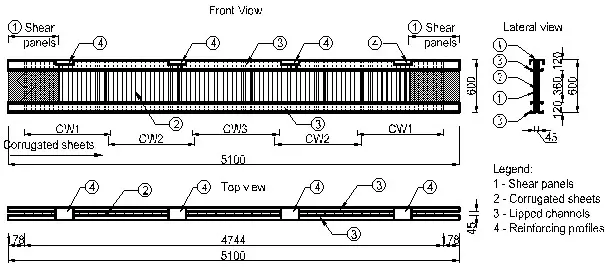
Corrugated web beams satisfy the principle of efficient material distribution i.e., the flange material must be as far apart as possible, with minimum connecting material between the flanges, the web.
Their main components are: 1) the shear panels (flat steel sheets), 2) the corrugated sheets, 3) lipped channels (the flanges), 4) reinforcing profiles under the load application points, as presented in Figure 1.
Two corrugated web beams were built-up using spot welding (noted with SW1 and SW2 in the following) and three beams were built-up using MIG brazing (noted with CMT1, CMT2, and CMT3). For each case, shear lap specimens, of dissimilar sheet thicknesses, were tested to determine the capacity of the connection between the beam parts, as shown in Figure 2.
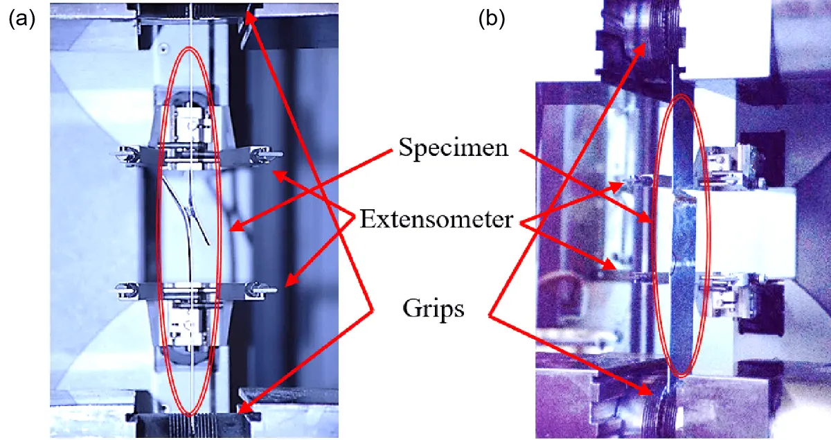
Figure 2. Shear lap joint specimens (a) Spot welded; (b) MIG brazed. MIG: Metal Inert Gas.
As expected, the spot-welded shear lap joint specimens have smaller capacity due to the smaller connecting surface, but it is also noticed that while the capacity for MIG brazed specimens the maximum force is similar for all combinations of thicknesses as it is dictated by the thinner sheet, for the spot welded lap joint specimens, the resistance depends on the combinations of thicknesses connected, Figure 3 shows the 1.2 mm sheets joint with 1.2, 1.5, 2.0, 2.5 mm sheets.
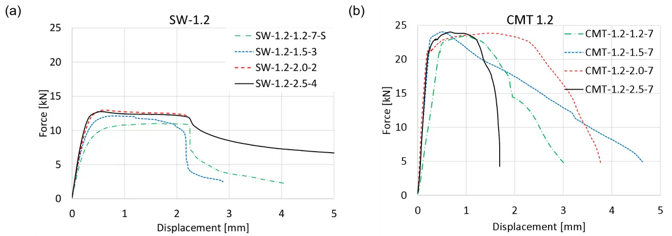
Figure 3. Shear lap joint response. (a) Spot welded; (b) MIG brazed. SW: Stud Welding; CMT: Cold Metal Transfer; MIG: Metal Inert Gas.
Also, a higher ductility is noticed for the SW specimens while the MIG brazed specimens show an increased capacity but a dispersed and non-consistent ductility.
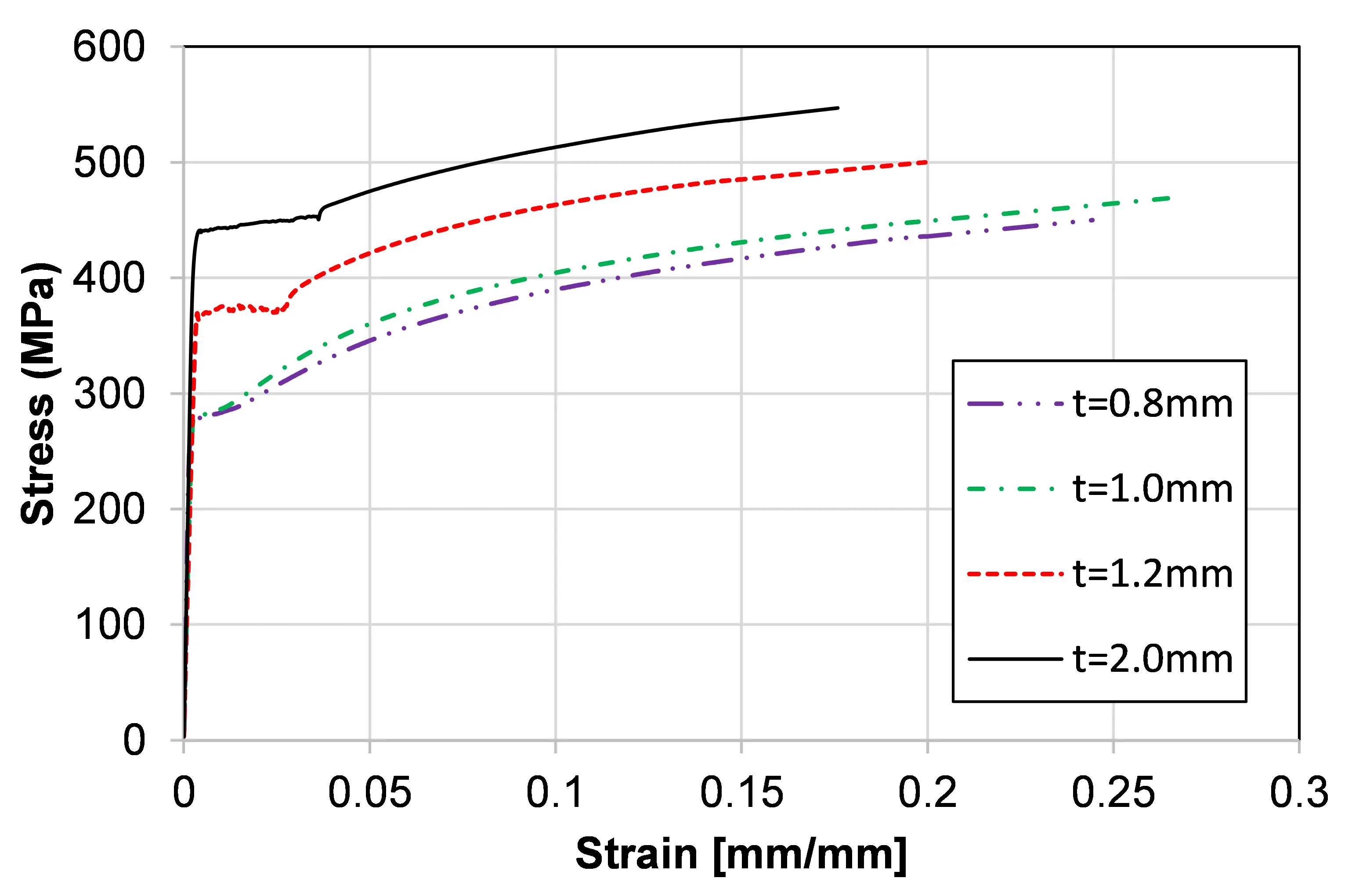
For reference values, tensile tests were performed on each thickness of the steel sheet, as the properties of the material obtained in Table 1 will represent the basis for further numerical investigation.
Table 1. Measured properties of the cold-formed steel
| t (mm) | Rp0.2 (MPa) | Rm (MPa) | Ag % | At % |
| 0.8 | 279.64 | 361.76 | 18.23 | 26.60 |
| 1.0 | 281.33 | 373.50 | 16.40 | 26.14 |
| 1.2 | 366.82 | 420.68 | 12.77 | 19.83 |
| 1.5 | 407.70 | 497.12 | 12.80 | 20.38 |
| 2.0 | 431.78 | 464.46 | 11.55 | 19.70 |
| 2.5 | 374.68 | 452.98 | 11.16 | 16.76 |
Rp0.2: stress at 0.2% strain; Rm: stress corresponding to the maximum force; Ag: plastic extension at maximum force; At: total extension at the moment of fracture.
2.2 Experimental tests on beams
The test setup of the beams is presented in Figure 4. The corrugated web beam is fixed at both ends while the leverage system transmits the load from the actuator to four points situated at the distances of L/8 | L/4 | L/4 | L/4 | L/8. Although several connections must be performed for the built-up of such beams, the interest of this study is represented by the bolted connection at the end of the beams, (4) and (5) in Figure 4b.
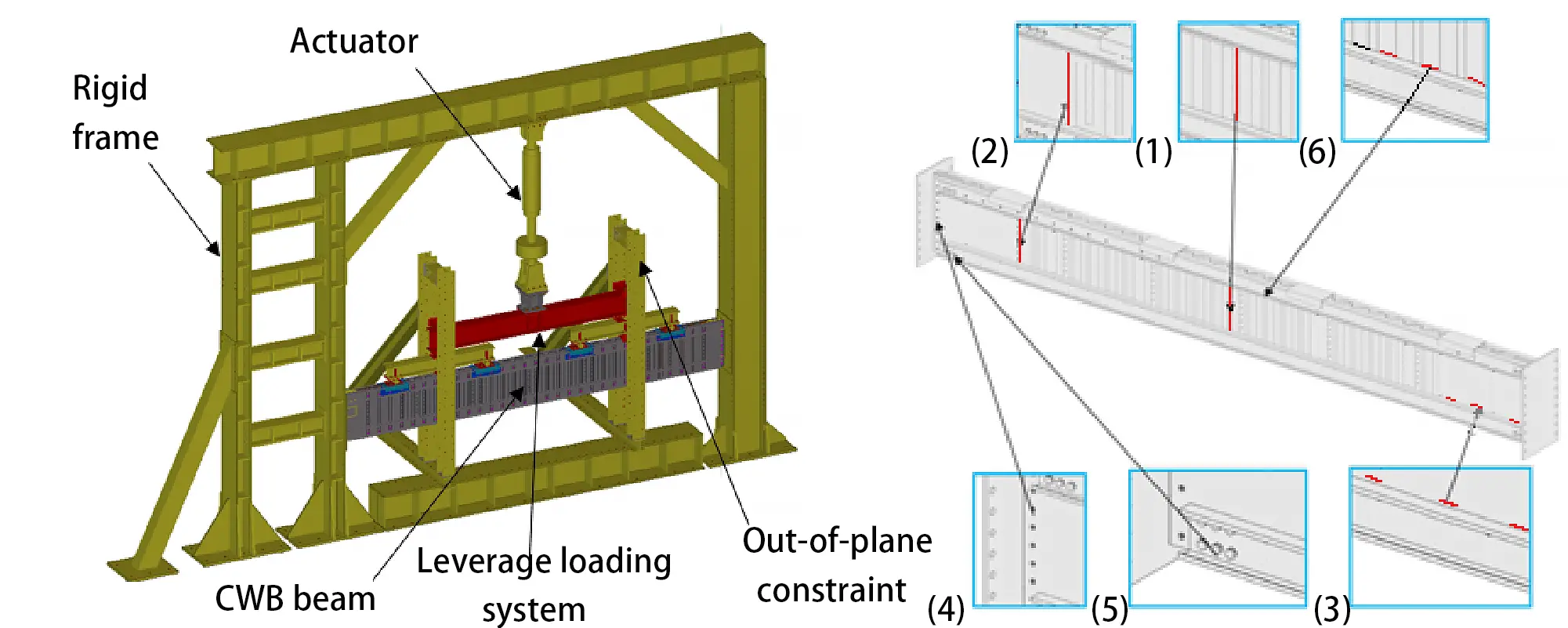
Figure 4. (a) Test setup; (b) Connections of a corrugated web beam. CWB: corrugated web beams.
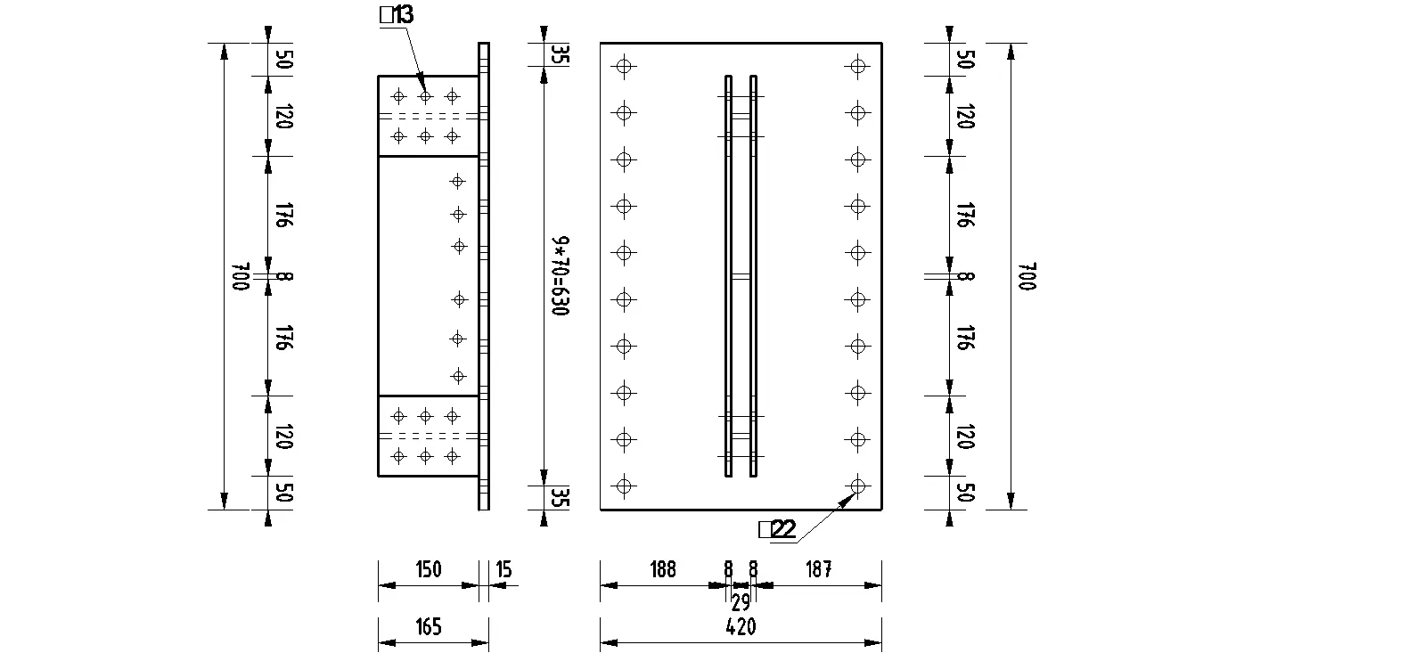
The assembly designed to fix the beam ends uses steel plates of 8 mm and 15 mm as fins and end plate, respectively. The configuration of the assembly is depicted in Figure 5, having holes for the beam parts (flange/shear panels) connections and holes for the support structure the 13 mm and 22 mm diameters, respectively, as shown in Figure 5. M12, gr. 8.8 bolts were used for connecting the cold-formed parts, flanges and shear panel, to the support device assembly and M20, gr. 10.9 bolts for connecting the assembly to the support structure, the testing rig.
The deflections of the beams were recorded at each quarter of the beam by two wire displacement transducers, one for each side of the bottom flange, as shown in Figure 6a, while the connection was monitored by linear variable displacement transducers (LVDT) in the following manner. An LVDT was fixed on each flange lipped channel, at the last of the three bolt columns with the rod touching the end plate of the support device, monitoring the slippage between the flanges and the support device. Another LVDT was fixed on the 8 mm plates of the support device having the rod touching the rigid testing frame and monitoring the deformation of the end plate. Because deformations of the endplate were expected only due to the tensile forces, these deformation monitors were installed at the top flanges of both ends of the beam. At the bottom flange, only the two slippage monitors were used at each beam end.
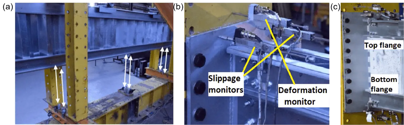
Figure 6. (a) Vertical deflection measurement positions; (b) Deformation and slippage measurements for top flange; (c) 3 LVDT for top flange, 2 LVDT for bottom flange. LVDT: linear variable displacement transducers.
2.3 Numerical simulations
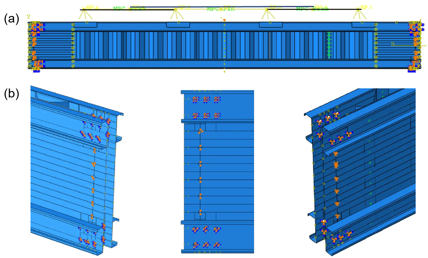
Due to the stress concentration in the connection area which cannot be monitored using common laboratory equipment, numerical analyses were performed for the full scale beam specimens using Abaqus v. 6.14[15].
The built-up beam parts were defined as extruded 3D shell elements according to the shape of the part. An approximate global size of 15 mm was set for the definition of the element dimensions. The S4R finite element type, 4-node doubly curved thin or thick shell, reduced integration, hourglass control, finite membrane strains, was selected for the computation considerations.
The material models for all the parts of the built-up beams were defined considering the results of the tensile tests performed on the base material presented in Section 2.1 and those reported by previous researchers[8]. The obtained values were transformed into the True-Stress-Strain relations according to EN 1993-1-5, Annex C[1], as shown in Figure 7.
The spot welds were defined using the Fastener command, with the Point-based option, to which Attachment points, defined in the Assembly of the model, were assigned.
A Physical Radius was defined, function of the connected thicknesses, and the Connector Section was assigned. The Connector Section behavior was considered by the Elasticity (rigid), Plasticity (yield force = 12,200 N), Failure (± 10) and Damage (initiation ± 12,200 N). These properties were calibrated based on the experimental results on lap joint tensile-shear tests and function of the connected steel sheet thicknesses.
For the MIG brazed model, the connection between the beam parts was defined as Tie constraint. The use of Tie constraint allows the connection to consider the beam parts material properties as the lap joint specimens failed either in the base material or close to the brazing but not in the deposited material of the brazing.
While the support conditions were defined on the nodes of the holes provided for the bolts that connect the beam to the end plate assembly as null displacements and rotations, as shown in Figure 8b, the loading of the beam was defined as a vertical displacement in a set of multipoint constraints MPC that forms a leverage system to transmit the deflection to the 4 loading points as shown in Figure 8a.
Due to the multitude of contact areas, the All*with self-option was used for the interaction between parts with a Penalty formulation of 0.1 Friction Coefficient, for the tangential behavior and Hard contact for the normal behavior.
3. Results
3.1 Response of the beams
Several differences are observed in the response of the corrugated web beams with two types of connections between the parts i.e., spot weld and MIG brazing. Figure 9 presents the recorded force versus the midspan deflection of the five tested beams.
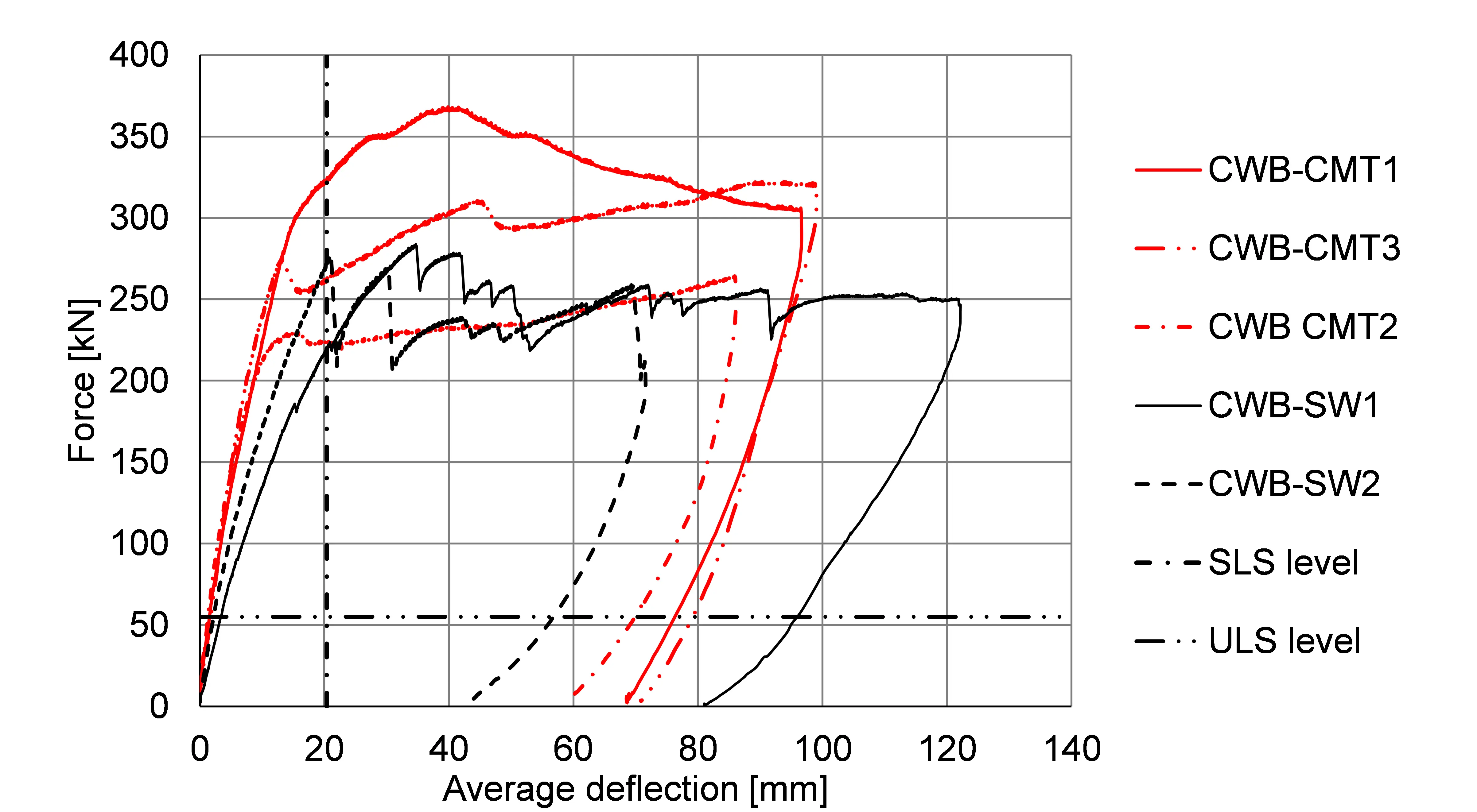
Figure 9. Force-deflection curves of the corrugated web beams. CWB: corrugated web beams; CMT: Cold Metal Transfer; SLS: serviceability limit state; ULS: ultimate limit state.
Considering the observations in Section 2.1 regarding the response of the lap joint specimens, although the MIG brazed connection does not offer a reliable ductility, the effect of the shape of the connection (line connection), makes the MIG brazed beams to exhibit an increased rigidity compared to the SW beams, mainly because the connection between the parts, long brazing throats, offers good stability of the web corrugations. Also, the maximum forces recorded during testing are bigger for the MIG brazed beams. For the SW specimens, the relatively regular force drops represent failure of the spot weld connections between the web and the flanges, mostly nugget pull-out.
Two limits were defined, one for the Ultimate Limit State (ULS) and the other one for the Serviceability Limit State (SLS), as presented in Figure 9. These limits are 55 kN for ULS (corresponding to the most common design load combination in Romania, that is, 1.35 Permanent Load + 1.5 Snow Load) and 20.4 mm (L/250) for SLS, respectively. These built-up beams satisfy the above criteria with a small material consumption.
Although local buckling of the shear panel or local buckling of the corrugation appear, the force drops for both type of the connection of the beams refers to the development of the local buckling of the corrugation into buckling of the corrugated panels. An image of the final stage of one of the corrugated web beams, CWB-SW2, is presented in Figure 10, where buckling of the shear panels and shear buckling of the corrugated panels are visible from the top to the bottom flange. Figure 11 and Figure 12 present the failures encountered during testing, the first failure being the buckling of the shear panel. Also, regarding this failure, the high bending rigidity of the beam forces the deformations towards the end of the beam and therefore to the connection of the beam.
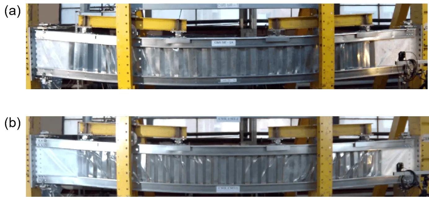
Figure 10. Deformed shape of the CWB after testing (a) SW1; (b) CMT2. CWB: corrugated web beams; SW: stud welding; CMT: cold metal transfer.
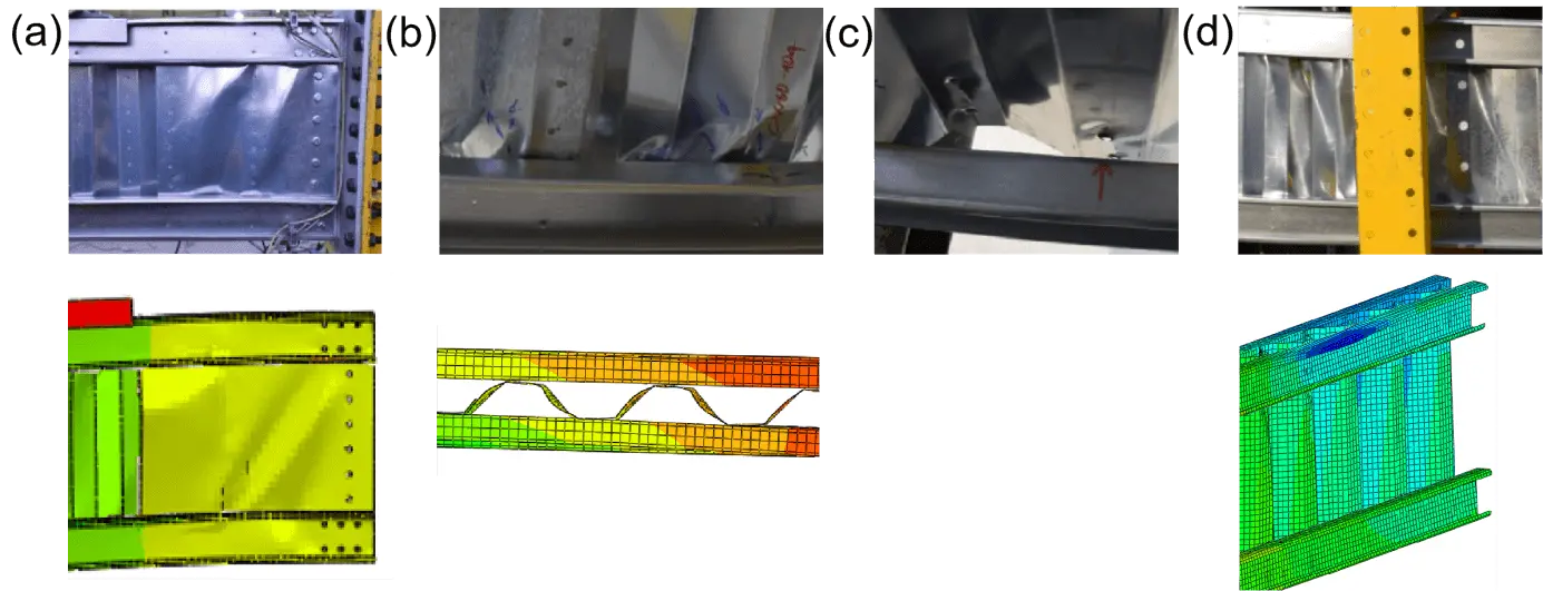
Figure 11. Failure stages of CWB-SW1. (a) Shear panel buckling; (b) Corrugation distortions; (c) Spot welding failure; (d) Buckling of the web panel. CWB-SW1: corrugated web beams-stud welding1.
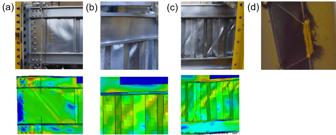
Figure 12. Failure stages of CWB CMT-1. (a) Buckling of the shear panel; (b) Buckling of the corrugation; (c) Buckling of the web panel; (d) Fracture of a brazing in the shear panel. CWB: corrugated web beams; CMT: cold metal transfer.
The two cases, Figure 11c and Figure 12d are not applicable as the connector model for the SW represents a force-displacement graph of the response between two points, where the failure is dictated by the zero force, and fracture of the deposited material did not occur in the lap-joint shear-tensile tests which means a flaw in the manufacturing of the brazing.
3.2 Beam connection recordings
The following will emphasize the biggest values of the slippages and deformation recorded in the beam end connection. The nomenclature of the recordings has the following meaning:
- D - Displacement
- H - horizontal direction
- C - center plane of the beam (deformation of the end plate)
- L - left connection (according to Figure 10)
- R - right connection (according to Figure 10)
- T - top flange
- B - Bottom Flange
- 1 - LVDT in the frontal plane according to Figure 10 (2 is for the LVDT’s in the backward plane).
Due to the smaller forces applied to the SW beams the deformation of the end plate (DHCLT and DHCRT) is limited to maximum 2 mm, as shown in Figure 13, while for CMT-1, where the maximum force was reached, the end plate deformed over 4 mm, as shown in Figure 14.
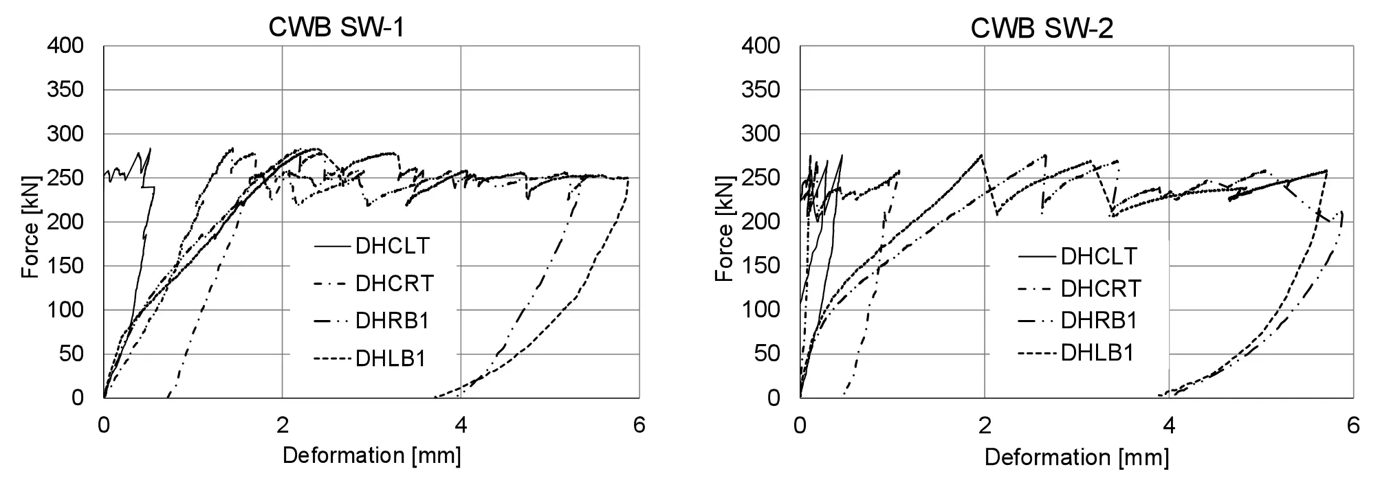
Figure 13. Slippages and deformation at SW beam ends. CWB: corrugated web beams; SW: Stud Welding.
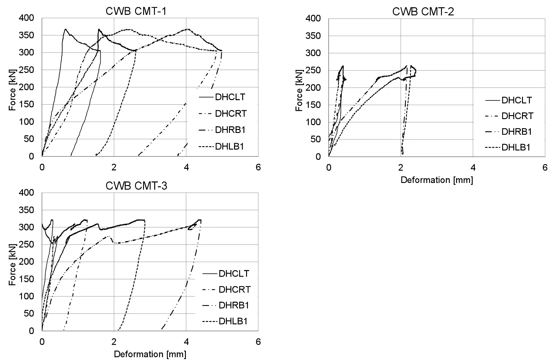
Figure 14. Slippages and deformation at MIG brazed beam ends. CWB: corrugated web beams; CMT: cold metal transfer; DHCLT: direct heat control and laser technology; DHCRT: direct heat control resistance welding technology; DHRB1: direct heat resistance brazing 1; DHLB1: direct heat laser brazing 1.
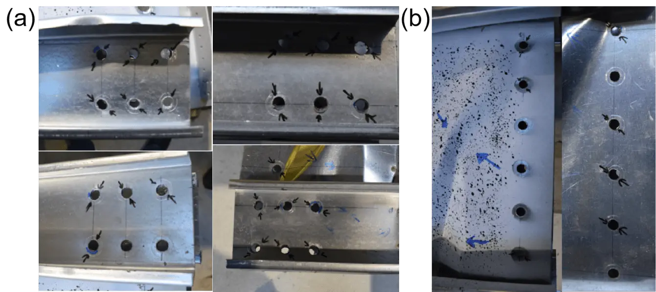
Although a tolerance of just 1 mm was considered for the M12 bolts which connect the beam parts to the support device, the recordings show a much larger value for the slippage. Nevertheless, these values are highly probable to appear as suggested by the deformation of the bolt holes presented in Figure 15.
3.3 Numerical analyses results
The numerical simulations were performed to validate a model that can capture both the failure mechanism as well as the force-displacement curve recorded by the data acquisition system. The failure sequence and modes, encountered during the experiments, were replicated by the numerical model as presented in Figure 16: (a) shear panel buckling, (b) distortion of the corrugated web and (c) the local buckling of the flange at the load application points.
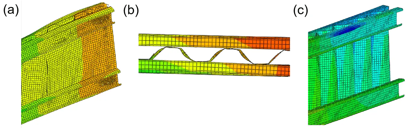
Figure 16. (a) Buckling of the shear panel; (b) Distortion of the corrugated steel plate; (c) Local buckling of the flange.
The quantitative results depicted in Figure 17 and Figure 18 with dashed lines for the numerical models also present a good correlation to the experimental results obtained for the SW beams and MIG brazed beams, respectively.
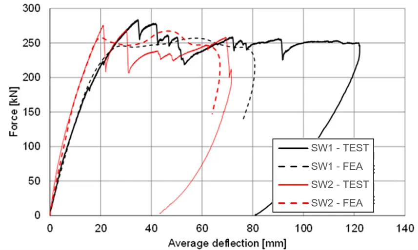
Figure 17. Experimental and numerical results. SW: stud welding; FEA: finite element analysis.
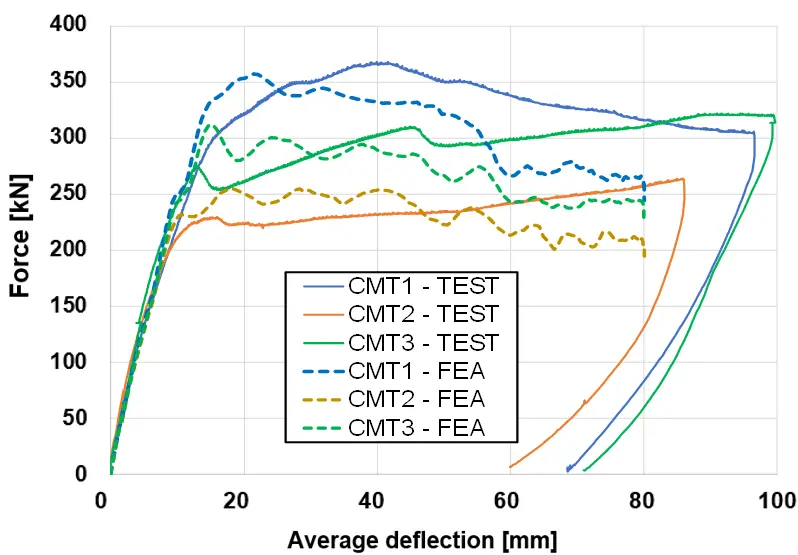
Figure 18. Experimental and numerical results. CMT: Cold Metal Transfer; FEA: finite element analysis.
From the validated numerical model, the stress distribution in the bolted connection of the beam can be visualized in the shape of maximum principal stresses, as shown in Figure 19. Plasticization of the material is produced for most of the holes but more severely for the holes in the lipped channels of the flanges which are supposed to counteract the bending moment in the beam.
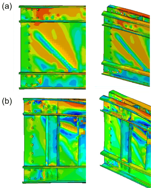
Figure 19. Stress distribution in the bolted connection: (a) CWB-SW1; (b) CWB-CMT1. CWB: corrugated web beams; SW: Stud Welding; CMT: Cold Metal Transfer.
Also, for the CWB-CMT1, which supported the highest force applied to the beams, the plasticization reached the holes closer to the supporting device, as shown in Figure 19b.
4. Conclusions
The built-up corrugated web beams of cold-formed profiles represent a feasible structural element especially if the manufacturing process time can be reduced by using an automated process for connecting the main parts of the beam, i.e. spot weld and MIG brazing.
The experimental results of full-scale beams using spot welding have shown that both the capacity and the ductility obtained for the tested specimens are very good. The instability phenomena recorded during the tests are replicated by the numerical model, as well as the response of the beams in terms of bearing capacity and rigidity.
The experimental results of full-scale specimens using MIG brazing showed that both the capacity and the ductility obtained for the tested specimens are very good, but compared to the solution using spot-welding, the results show an increased rigidity mainly due to the stabilizing effect of the brazing; a higher capacity may be attained but depends on the web thicknesses.
The major advantage of MIG brazing joints is considered to be the increased stability of the corrugations as no distortion of the web corrugations was recorded. A disadvantage of the current solution is the increased manufacturing time compared to the spot welding solution.
The results obtained from the numerical analysis, similarly, catch the response of the experimental investigations on the real-scale beams, both from qualitative and quantitative results.
Considering the deflection of the beam limited to L/250, approximately 20 mm, the rigidity of the beam is sufficient to satisfy the serviceability limit state criterion presented before.
Regarding the capacity at ULS, if the maximum force is distributed over the length, a value of at least 40 kN/m can be resisted by the corrugated web beam that corresponds considering a bay of 5 m to 8 kN/m2, capacity that is 2.5 times higher than the snow loading considered in the Romanian code.
Special attention must be paid to the deformation of the thin steel sheets in the connection at the end of the beam. The deformation is not necessarily related to the bolted connection deformation but also to the local deformation of the profiles such that a minimum thickness for the profiles must be provided or the connection should be reinforced with other profiles.
Parametric studies will follow the evaluate the suitability of the corrugated web beams with cold-formed thin-walled elements, for larger spans.
Authors contribution
All authors contributed equally to this work.
Conflict of interest
The author declares no conflicts of interest.
Ethical approval
Not applicable.
Consent to participate
Not applicable.
Consent for publication
Not applicable.
Availability of data and materials
Not applicable.
Funding
The research was financed by “Internal program for stimulating and rewarding the teaching activity” 2021, Politehnica University of Timisoara, Romania, contract no. 10165/11.06.2021.
Copyright
© The Author(s) 2022.
References
-
1. CEN [Internet]. EN 1993-1-5, Eurocode 3: Design of steel structures - Part 1-5: Plated structural elements; 2006. Available from: https://www.phd.eng.br/wp-content/uploads/2015/12/en.1993.1.5.2006.pdf
-
2. CEN [Internet]. EN 1993-1-1, Eurocode 3: Design of steel structures - Part 1-1: General rules and rules for buildings; 2005. Available from: https://www.phd.eng.br/wp-content/uploads/2015/12/en.1993.1.1.2005.pdf
-
3. CEN [Internet]. EN 1993-1-3, Eurocode 3: Design of steel structures. Part 1-3: General Rules. Supplementary rules for cold-formed thin gauge members and sheeting; 2006. Available from: https://www.phd.eng.br/wp-content/uploads/2015/12/en.1993.1.3.2006.pdf
-
4. Pasternak H, Kubieniec G. Plate girders with corrugated webs. J Civil Eng Manage. 2010;16(2):166-171.[DOI]
-
5. Dubina D, Ungureanu V, Gilia L. Experimental investigations of cold-formed steel beams of corrugated web and built-up section for flanges. Thin-Walled Struct. 2015;90:159-170.[DOI]
-
6. Dubina D, Ungureanu V, Gilia L. Cold-formed steel beams with corrugated web and discrete web-to-flange fasteners. Steel Constr. 2013;6(2):74-81.[DOI]
-
7. Phan DK, Rasmussen KJR. Flexural rigidity of cold-formed steel built-up members. Thin-Walled Struct. 2019;140(8):438-449.[DOI]
-
8. Ungureanu V, Both I, Burca M, Radu B, Neagu C, Dubina D. Experimental and numerical investigations on built-up cold-formed steel beams using resistance spot welding. Thin-Walled Struct. 2021;161(2):107456.[DOI]
-
9. Ungureanu V, Both I, Tunea D, Grosan M, Neagu C, Geirgescu, et al. Experimental investigations on built-up cold-formed steel beams using MIG brazing. Proceedings of the Eighth International Conference on Thin-Walled Structures-ICTWS. 2018 July 24-27; Lisbon, Portugal. 2018. p. 24-27. Available from: https://www.semanticscholar.org/paper/EXPERIMENTAL-INVESTIGATIONS-ON-BUILT-UP-COLD-FORMED-Ungureanu-Both/bbe4fd280368df012348f21df5b678438b7b217b
-
10. Elgaaly M, Seshadri A, Hamilton RW. Bending strength of steel beams with corrugated webs. J Struct Eng. 1997;123(6):772-782.
-
11. Elgaaly M, Seshadri A. Girders with corrugated webs under partial compressive edge loading. J Struct Eng. 1997;123(6):783-791.[DOI]
-
12. Briskham P, Blundell N, Han L, Hewitt R, Young K, Boomer D. Comparison of self-pierce riveting, resistance spot welding and spot friction joining for aluminium automotive sheet. SAE Technical Papers; 2006.[DOI]
-
13. Iordachescu D, Quintino L, Miranda R, Pimenta G. Influence of shielding gases and process parameters on metal transfer and bead shape in MIG brazed joints of the thin zinc coated steel plates. Mater Des. 2006;27(5):381-390.[DOI]
-
14. Kumar NP, Vendan SA, Shanmugam NS. Investigations on the parametric effects of cold metal transfer process on the microstructural aspects in AA6061. J Alloys Compd. 2016;658:255-264.[DOI]
-
15. Dassault Systemes Simulia [Internet]. Abaqus 6.14 Documentation; 2014. Available from: https://www.scribd.com/document/517828704/Analysis-4
Copyright
© The Author(s) 2022. This is an Open Access article licensed under a Creative Commons Attribution 4.0 International License (https://creativecommons.org/licenses/by/4.0/), which permits unrestricted use, sharing, adaptation, distribution and reproduction in any medium or format, for any purpose, even commercially, as long as you give appropriate credit to the original author(s) and the source, provide a link to the Creative Commons license, and indicate if changes were made.
Publisher’s Note
Science Exploration remains a neutral stance on jurisdictional claims in published
maps
and institutional affiliations. The views expressed in this article are solely those
of
the author(s) and do not reflect the opinions of the Editors or the publisher.
Share And Cite


Science Exploration Style
Both I, Bodea F, Ungureanu V. The Effect of Connections on the global response of built-up cold-formed steel beams with corrugated webs. J Build Des Environ. 2023;1:6461. https://doi.org/10.37155/2811-0730-0101-2
Tips
Copy completed.
Submit a Manuscript
Author Instructions
Cite this Article
Article Metrics
0
View
0
Download
Cited
Article Updates

Science Exploration Style
Both I, Bodea F, Ungureanu V. The Effect of Connections on the global response of built-up cold-formed steel beams with corrugated webs. J Build Des Environ. 2023;1:6461. https://doi.org/10.37155/2811-0730-0101-2
copy
Share Link
copy