MEMS smart glass for personalized lighting and energy management in buildings: working principles, characterization, active light steering, thermal management, energy saving considering different locations on earth, comparison of different smart glass technologies
Dennis Löber
1,2
,
Md Kamrul Hasan
1

,
Steffen Liebermann
1,2
,
Mustaqim Siddi Que Iskhandar
2
,
Shilby Baby
2
,
Jiahao Chen
1
,
Eslam Farrag
1
,
Naureen Ahmed
1
,
Shujie Liu
1
,
Basma Elsaka
1
,
Muhammad Hasnain Qasim
1
,
Guilin Xu
2
,
Hartmut Hillmer
1,2,*
*Correspondence to:
Hartmut Hillmer, Institute of Nanostructure Technologies and Analytics (INA) and Center for Interdisciplinary Nanostructure Science and Technology (CINSaT), University of Kassel, 34109 Kassel, Hessen, Germany; Nanoscale Glasstec GmbH, 34132 Kassel, Hessen, Germany.
E-mail: hillmer@ina.uni-kassel.de
J Build Des Environ. 2023;1:22962. 10.37155/2811-0730-0201-14
Received: October 02, 2023Accepted: December 25, 2023Published: December 31, 2023
This article belongs to the Special lssue Urban & Building Daylighting-Thermal Performance and Interactive Research
Abstract
A detailed quantitative overview on different micro-electro-mechanical systems (MEMS) smart glass technologies and smart glass technologies in general is given. Next, our MEMS smart glass is focused. This technology based on millions of miniaturized, tiltable, planar mirrors. Installed in windows or building facades, it allows personalized daylight steering as well as thermal and energy management in buildings via electrostatic actuation, strongly supports health and has a large potential for reducing CO2 emissions and energy consumption of buildings, noticeably. Various results of experimental characterizations and reliability studies are summarized. Simulations of light steering are reported for different use cases involving tailored variable tilt angles of the mirrors. Ray tracing is used to visualize light steering and distribution in a model room, showing that our MEMS smart glass can generate high illuminance where necessary in workspaces. Finally, simulations of energy savings are presented using hourly resolved real weather data over up to 10 years, varying cloud coverage, daytime and seasonal varying irradiance via varying sun orbit, respective geo coordinates of different locations, energy price and others. Simulation results are depicted for four German and two international cities, varying in latitude and elevation. Huge energy saving potential of our MEMS smart glass and amortization of investment in MEMS smart glass within less than five years in the best case is reported compared to conventional window blind systems.
Keywords
Energy saving, green technologies, smart window, thermal and energy management, personalized daylight steering
1. Introduction
Over the last decades the negative influence of humanity on global climate has become consensus in the scientific community. Above all, the emission of greenhouse gases was identified as the driver of global warming[1]. Climate change has caused several negative aftereffects on the entire planet like global warming, the swift increase in sea levels at a rate of 3.3 mm annually, and adverse effects on human health stemming from an unstable ecosystem[2-4]. Due to increasing negative influence on mankind the topic had also come into public eye in recent years which has resulted in a rethinking in the climate policy of many states[5]. As per the “Paris Agreement” of 2015[6] signed by 54 countries, including Germany, it is imperative to implement effective measures informed by cutting-edge science and technology to fight the challenges posed by climate change. Despite that, the global anthropogenic greenhouse gas emission in the last decade (2010-2019) increased compared to the former[1]. This ever-increasing trend will persist and intensify unless immediate steps are taken to implement countermeasures[2-4]. Moreover, it was declared that a substantial reduction in the risk of climate change can be achieved by limiting the global average temperature increase to within 2 °C. When exploring alternative methods of energy production beyond conventional techniques, renewable sources such as Wind, Water, and Sunlight are regarded as primary resources with the potential to conserve a significant portion of Earth’s energy, replacing the need for fossil fuels[7].
Globally, existing buildings alone account for the largest share of energy consumption, accounting for 50%, leading to huge CO2 emissions. Additionally, a vast majority of building stocks are energy inefficient, with only a minimal percentage undergoing renovation each year[8-10]. The report from the German Federal Ministry for the Environment, Nature Conservation, and Nuclear Safety in March 2021 disclosed that, from 1999 to 2020, buildings surpassed the manufacturing and energy industries to become the third-largest contributors to CO2 emissions[11]. As per the “Building Report KOMPAKT 2019” by the German Energy Agency, space and water heating, along with lighting, are identified as the primary factors contributing to energy consumption in buildings[12]. Windows and glazing are integral components of buildings, serving a crucial role in ensuring effective insulation by minimizing heat loss and harnessing solar heat. They also provide natural light, ventilation, and pleasant outdoor views for occupants. Adjusting solar heat gain can enhance the energy efficiency of windows when compared to standard walls. However, a significant portion of glazing worldwide lacks energy efficiency, often featuring single glazing or early double glazing without low-emissivity (low-e) coatings[13]. Furthermore, windows are often regarded as the least energy-efficient component of a building, as they account for a major portion, approximately 60% of total energy loss due to heat conduction, convection, and radiation. This inefficiency translates into increased energy demands for both heating and cooling purposes[14].
The concept of ‘Smart Green Buildings’ has gained significant attention recently, emphasizing the importance of incorporating energy-efficient equipment in all buildings while increasing the use of renewable energy sources within the national energy mix. Nevertheless, optimizing energy consumption and its simultaneous reduction through readily available natural resources, such as utilization of solar radiation for lighting, heating, and cooling, will play a pivotal role. Earlier misconceptions about daylight having no discernible positive impact on human health and workplace hygiene, which may have contributed to the widespread adoption of artificial lighting, have now been re-evaluated from a more practical perspective. This shift in viewpoint is leading regulatory standards to place greater emphasis on occupational health over the visual performance[15]. For example, among numerous recent studies, the “Light and Health” investigation conducted in 1990 stands out as a comprehensive analysis that took various factors into account. This study proves that workers near the vicinity of windows within a commercial building encounter the lowest levels of health risks since they experience reduced fatigue, dizziness, job dissatisfaction, depression, tension, and disruptions in their natural working rhythm[16]. Hence, daylight is favored over artificial lighting because of its availability, illuminance with a full spectrum, variation in incident angles, as well as color and intensity. These attributes have a multitude of positive effects on human health and well-being like driving proper fundamental biological processes, reducing the risk of myopia by a factor of five, and shortening the hospitalization periods for patients with severe and refractory depression, among other benefits, as presented by numerous studies[17,18].
2. Smart Glass Overview
2.1 Comparison of smart glass technologies
Architects have overcome the historical reluctance to incorporate extensive window areas into building designs due to concerns about higher thermal transmittance values compared to opaque building elements. A contemporary trend in recent years involves pushing the envelope by implementing a higher Window-to-Wall Ratio (WWR) in building facades, often surpassing regulatory standards. This is achieved through the use of high-performance glazing systems, inc luding dynamic switching, to harness sunlight effectively and meet energy demands. In the European Union (EU), for instance, the WWR in buildings has doubled since 1980[13]. Various research studies have consistently demonstrated that harnessing daylight through a high WWR holds the greatest potential for achieving significant energy savings and, consequently, significant reductions in CO2 emissions[14-16,19,20]. Nonetheless, a high WWR introduces a significant drawback for building occupants, primarily excessive glare caused by uncontrolled daylighting at unfavorable angles. To mitigate these issues, window blinds are commonly employed to regulate uncomfortable incoming light. However, this often requires artificial lighting to compensate for the reduced natural light due to the employment of window blinds. Moreover, due to the common practice of placing the windows on one side of the room, only nearby areas are illuminated by the natural illumination, leaving distant sections darker and more reliant on artificial lighting to achieve a consistent light distribution across the entire room space. A numerous number of smart window technologies have been developed based on the features of the optimum daylighting technologies. Many of these technologies are now currently available in the commercial market. For example, sun shading systems like photochromic, thermochromic, electrochromic, and gasochromic systems, together with active window systems like Polymer Dispersed Liquid Crystal Display (PDLC), Suspended Particle Devices (SPD), as well as light steering systems such as light shelves, window blinds and light directive films, have been developed to eliminate the disadvantages of uncontrolled daylighting[17,18,21].
In an optimum daylighting system, maximum utilization and homogeneous distribution of daylight, flexibility to satisfy distinct light requirements, lighting, cooling and heating load reduction, efficient, clear view through, higher switching speed, low maintenance requirement and power consumption, as well as cost-effective manufacturing, installation and usage, are expected. Excellent homogeneities of the material thicknesses and compositions, high material purity to avoid unwanted absorption, a low minimum transmissivity Tmin (closed state), high maximum transmissivity Tmax (open state), large modulation contrast Tmax/Tmin, high switching speed, low haze, low temperature sensitivity, long lifetime, and low sensitivity for solar UV radiation are considered as important characteristic parameters. However, the above mentioned smart window technologies fulfil the requirements only to a very limited extent.
With the aim of efficient utilization of daylight in the best possible way, intelligent smart window technology comprised millions of electrostatically actuatable (MEMS)-based micromirrors inside double glazing windowpane (Figure 1) in an inert gas (argon, krypton or xenon) environment has been developed at the Institute of Nanostructure Technologies and Analytics (INA), University of Kassel[19,20,22-29]. The micromirrors arranged within the windowpane are protected from dust, damage due to strong wind, window cleaning, and adverse weather conditions which increases the lifetime and overall stability. These miniaturized micromirrors, which are imperceptible to the naked eye from distances greater than 25 cm, have long lifetime, high stability, low power consumption capability, high energy saving potential[16], cost effectiveness, fast switching speed and large operating temperature range.
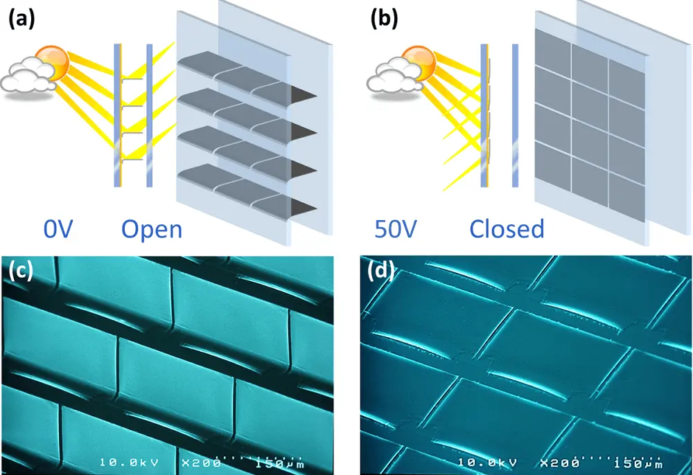
Figure 1. Micromirror in open (0 V, (a), (c)) and close (50 V, (b), (d)) state, from a side perspective. They are arranged in an inert gas atmosphere inside insulated double-glazed windowpane and sealed with butyl, as illustrated in (a) and (b) as schematic diagram and their respective SEM micrographs in (c) and (d). Reproduced with permission from[16]. SEM: scanning electron microscopy.
The individual micromirror with three primary parts; anchor, hinge and mirror plane, is fixed at one side—nearly identical to a hinged door. Micromirror is made of a combination of aluminium-chromium-aluminium-aluminium in multi-layer stack formation. The residual stress presence in the multi-metal thin layers at the hinge area is responsible for the deflection of free standing micromirror at an angle of 90° with respect to the substrate (Figure 2 and Figure 3) with a flat mirror plane due to localized stress compensation. When the potential difference is applied between the mirror plane and counter bottom electrode, the micromirror can be held in different intermediate angles (tilting angle Φ) by balancing the electrostatic attraction force and restoring force induced by the residual stress, before it reaches the critical pull-in angle where it snaps horizontal to the substrate due to the well-known pull-in or snap-in effect. This principle enables dynamic light guiding via active control of reflection on the mirror surface. The recent development of 2D actuation in micromirror array - generating two angles, tilt Φ and torsion θ by optimum structured Transparent Conducting Oxide (TCO), which allows the tailored adjustment of electrostatic force[22,28]. This new generation of micromirrors enables efficient light steering throughout the day independent of the window orientation, user movement and sun position.
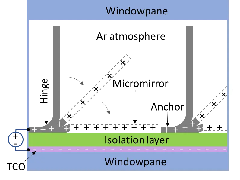
Figure 2. Schematic representation of an individual micromirror actuation concept in between the panes of a window glazing in an inert gas environment. Reproduced with permission from[16].
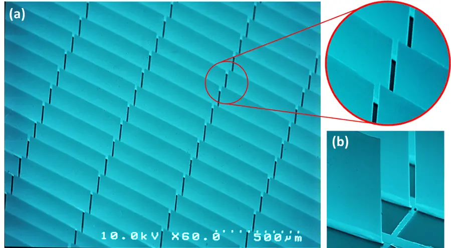
Figure 3. SEM micrograph of (a) free standing micromirror arrays after lift-off and drying process with an inset of a magnified area, (b) individual vertical standing flat mirror with ~90° opening angle. Republished with permission from[16]. SEM: scanning electron microscopy.
Based on the window orientation, latitude of the building, season, daytime and user presence, a nearly unlimited number of scenarios are possible. Four of those scenarios are displayed in Figure 4: Two of the micromirror states enable daylight guiding by explicit reflection towards the ceiling in the room, one reflection scenario to a wall and a completely closed state where the micromirrors are parallel to the windowpane due to electrostatic force to block the solar radiation. The solar radiation is reflected outside by switching all the micromirrors vertically in summer (very high solar impact) without any user in the room to keep the room cold. An automated control unit with data from an intelligent network sensing system that observes the position of persons, sun position, inside temperature and light ambience is therefore fed to execute the functionalities according to the requirements. During summer, when there is no user in the room, all the micromirrors are placed in closed position (parallel to the windowpane), saving huge cooling energy by minimizing the heat transfer into the room (Figure 4a). When user presence is detected during summer, some of the micromirrors (upper areas in Figure 4b) are kept open to reflect light towards the ceiling area above the user. However, the lower micromirrors are closed to keep the unoccupied room area, cool thus allowing energy saving by limiting the heat transfer into the room since only a certain number of mirrors are open.
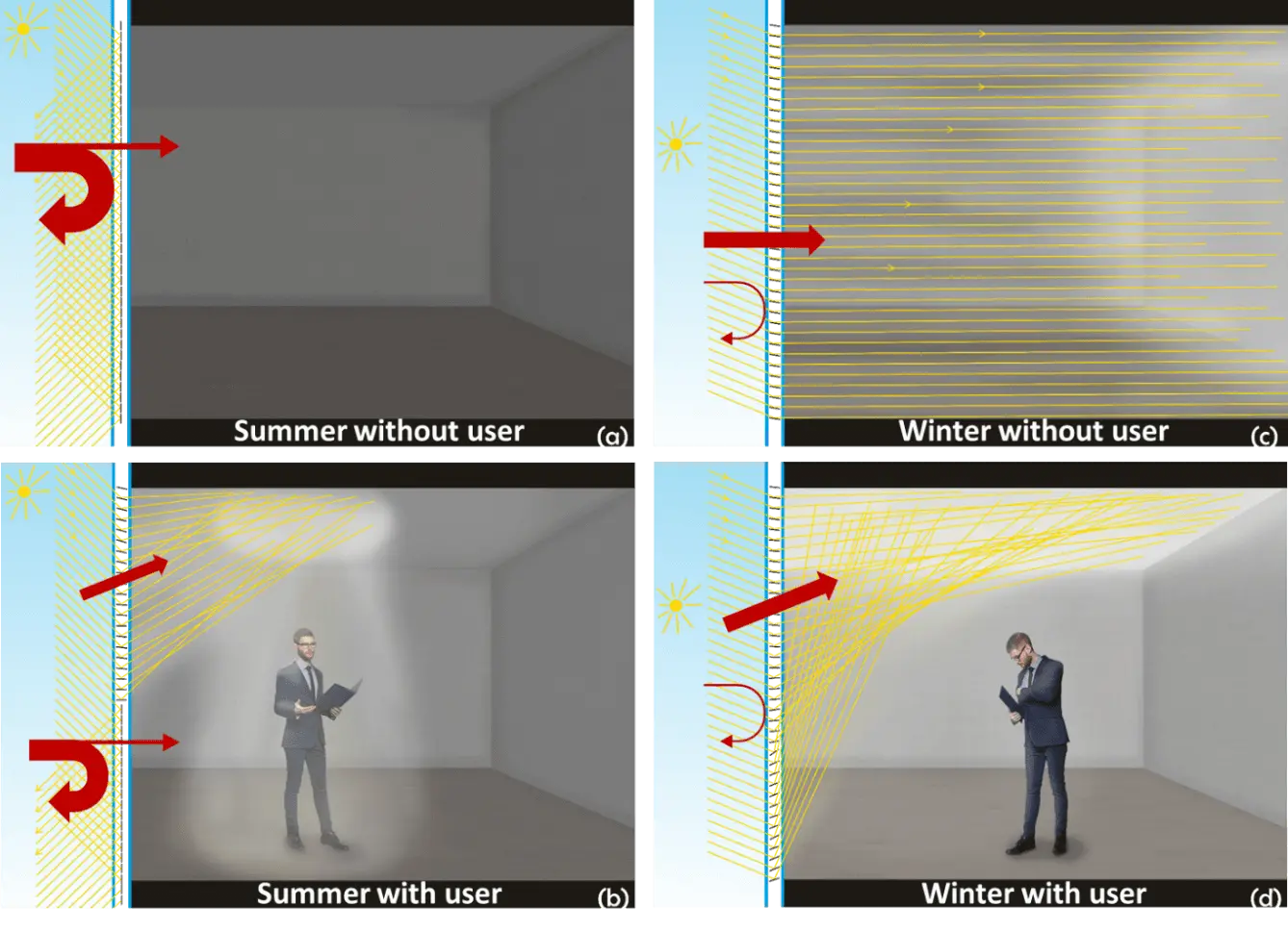
Figure 4. Illustration of a room equipped with a micromirror-array-based smart window and scenarios with and without users in different seasons, demonstrating light steering and heat energy management. (a) Summer, no user present: solar radiation is blocked by reflecting outside that keeps the room cool and saves huge energy; (b) Summer, user present: illuminates by deflecting light towards ceiling above the user and saves energy by limiting the heat transfer with closed micromirror in the lower areas; (c) Winter, no user: acts as a radiation heater by using all solar infrared and visible radiation to heat up the room; (d) Winter, user present: complete solar radiation is reflected towards the ceiling. Heat radiation coming inside the room is presented with red arrows. The widths of the red arrows symbolize the amount of heat energy, entering the room or being harvested, respectively. Republished with permission from[16] with permission of Leuze publishing house.
In addition, the illuminated spot on the ceiling can be moved with the user; thus, the inside area far away from the window can also be illuminated efficiently (Figure 4b). During winter with no user detected in the room, all the micromirrors are open to harvest energy efficiently by using the whole solar radiation to keep the room warm, similar to thermal component activation, thus saving the huge amount of energy required for heating (Figure 4c). When a user is present during winter, the solar radiation is directed towards the ceiling by keeping all the micromirrors open, however, with different angles using tailored actuation voltages. This saves energy needed for heating and lighting at the same time (Figure 4d). The general methodology, technological fabrication process, implementation of subfield addressing, reliability experiment, concept of clear view through have already been studied and reported in details[19,20,22-29].
Until now only flat windows installed in a 90° orientation in relation to the ground are discussed but windows are also installed in different orientations and the modules can be curved:
• Tilted but flat panes can be actuated in a similar way. After installation of the window, the tilt angle has to be entered into the smart glass control system. This is very simple if the tilt angle remains constant. In case the angle also varies, a tilt angle sensor has to be installed in addition to guarantee proper light steering via the MEMS smart glass.
• At the moment we also have fabricated and characterized MEMS smart glass on polymer foils[26], which can be bent easily in one direction but not in two.
• The process for MEMS smart glass on free-planes (2 bending directions or even more complex) has to be developed and is much more complex. This we will do in future for applications in e.g. cars and other mobile systems.
• Note that curved reflective glass can be potentially dangerous. And may inadvertently concentrate sunlight and melt materials on the opposite side of the street, as observed in certain instances by the Walkie-Talkie building (London UK), and the Walt-Disney concert hall (Los-Angeles USA)[30]. Thus, we would prefer flat panes if not desired by the customer, explicitly. Since the reflections of flat panes with closed reflective mirror array can reflect and illuminate other parts maximum with the intensity of direct sun light.
• We also developed another novel MEMS smart glass design using two different surface functionalities on the two sides of the mirror, to reduce reflections and avoid potentially dangerous situations outside in e.g., the traffic[29].
• We also developed curved micromirror arrays on polymer substrates[26].
A characteristic comparison of commercially available smart windows and our MEMS smart window is presented in Figure 5. Regarding transmission, the highest contrast between maximum and minimum transmittance is about a factor of 1,000 for conventional blinds and 7,700 for the MEMS smart glazing. On the other hand, all the other technologies exhibit significantly lower values, such as 60 for electrochromic systems and 120 for SPD technology. In terms of color neutrality, electrochromic technologies produce the least neutral results, whereas conventional blinds and MEMS smart glazing offer the best color neutrality.
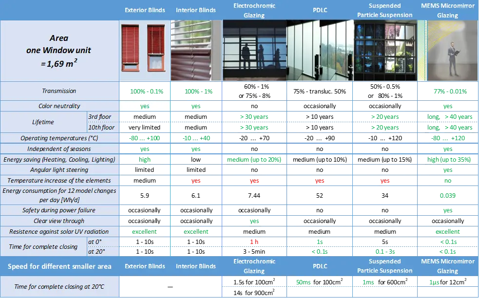
Figure 5. Comparison of different window technologies existing for light modulation and light steering. The colors represent the fulfilment of the requirement by the technology for specific parameter. Green: good; black: medium; red: bad fulfilment.
Concerning speed, considering one window unit, which corresponds to 1.69 m2: For conventional blinds, a complete open-to-closed status change can require 10 s and an adjustment is finished after about 1 s, whereas MEMS smart glazing’s are much faster (< 0.1 s) and furthermore independent of temperature. All the other technologies show a strong dependence on temperature for their functionality. The slowest switching speed (1 h) is observed for electrochromic technologies at 0 °C and the fastest (0.1 s) for SPD at 20 °C, among other technologies. Thus, the MEMS technology triumphs in this field. Note that switching speed is considerably dependent on size. We also fabricated much smaller MEMS micromirror arrays and measured a fastest closing time of 1 µs.
The shortest lifetime is exhibited by the exterior sunblinds while the longest is by the MEMS smart glazing resulting from the strong miniaturization of the mirrors.
The widest operating temperature range was measured for our MEMS micromirror glazing: ranging from low values of -80 °C up to 120 °C. It’s worth noting that we did not measure temperatures below -80 °C or above 120 °C due to the limitations of our equipment.
Electrochromic technologies, SPD, and PDLC are primarily optimized for summer rather than winter. As a result, their advantages are notably influenced by the season, making them highly season-dependent technologies. The functionality of our MEMS smart window is independent of season.
Conventional blinds have potential for light steering if the lamellae are completely flat and surface-coated with strongly reflective coatings like that of a bathroom mirror. Compared to the limited light-steering capabilities of other technologies, MEMS micromirror glazing stands out with significantly greater functionalities and a multitude of possibilities.
Technologies that rely partially or entirely on light absorption tend to convert the absorbed energy into heat. Consequently, a window equipped with such technologies can function as a radiant heater, which is particularly undesirable on hot summer days. Although these absorbing technologies effectively block near-infrared radiation (solar infrared), they re-emit it as mid-infrared radiation, depending on the temperature of the elements involved. In summary, undesired radiation heaters are avoided the most effectively in exterior blinds and MEMS smart glazing.
The energy consumption of a model day, defined as the energy needed for two full open-close-open cycles and 10 adjustments within a model day, is used to compare energy usage across various technologies. The energy consumption compared in Figure 5 is that for 12 actuations. The company WAREMA (selling external and internal blinds) gave us their exact motor powers and told us that in average per day the user is initiating two complete open-closed-open cycles and 10 adjustments of this mechanical blinds. However, a noticeable additional power consumption arises from holding a status in MEMS smart glass. In case of external and internal blinds, this does not apply. However, for all the smart glass systems this is a noticeable power consumption. There are reports for novel specific systems in a few cases, where publications report on no power consumption on holding (Section 5). Among these technologies, PDLC consumes the highest amount of energy (52 Wh/d), while our MEMS smart glazing records the lowest energy consumption (0.039 Wh/d). Considering much more activities, this results in a multiplication of the energy consumption by more or less the same factor. This means that the ratio between these different technologies remains approximatively the same. Scenarios of much more activities are considered in Section 2.3.
As previously highlighted, in the event of an abrupt power outage, both PDLC and SPD glazing have the potential to remain in an opaque state, posing a potential safety hazard due to the obstructed view from the outside during emergencies. In contrast, only MEMS smart glazing fully complies with all safety requirements in such situations.
When it comes to achieving a clear view through various technologies, electrochromic technologies currently offer the most favorable results.
In order to improve clear view through MEMS smart glass, our concept reduces diffraction effects by using as much as possible non-periodic micromirror shapes (irregular apertures) inside the arrays to reduce distortions and to provide a clearer view through the arrays. Theoretical studies using Fourier transform, as well as various optical transmission experiments, have been performed on different micromirror array designs. Arrays with irregular (non-periodic) and regular (periodic) have been compared for that purpose, using rectangular as well as trapezoidal apertures. Without any exception, all our experimental results have proven our hypothesis that non-periodic micromirror arrays are superior to periodic micromirror arrays. By varying geometrical dimensions of the apertures and the size of grating spacings, diffraction intensities of non-zero orders could be considerably suppressed[25,31]. On going efforts focus on enhancing clear view through MEMS smart glazing.
2.2 MEMS based smart glass
Next, this review provides an overview on MEMS solution for smart glass applications. Optical MEMS have been designed, fabricated and characterized for various light processing applications. Micromirror array-based MEMS have been presented for N × N switches in wavelength division multiplexing[32-34], for beamers[35,36], light steering via smart glazing for buildings[16,19,20,22-29,37] and adaptive optics[38,39]. Optical aberrations have been corrected in higher orders for applications in optical free space communication, astronomy, laser micromachining, maskless lithography and microscopic medical technology. Note that these MEMS mirror components are planar, and they are actuated electrostatically. Note also that some reflective adaptive optics exist reveal freeform shapes[40,41]. For switches and beamers[32-36], the mirror arrays are made of Si by MEMS standard processing and are planar. For light steering in smart glazing, the mirrors are metal based[27,37] and planarized using partial stress compensation.
Similar MEMS structure with metal-based but curled (rolled, i.e. non-planar) in their relaxed state, in contrast, are called microshutter arrays[42-47] or micro blinds[48]. Transmission modulation has been reported for these MEMS microshutter arrays for applications in smart glass[42,49], space instrumentation[43], camera shutters[45] and displays[46,49]. These MEMS microshutter arrays are curled in the open state (first state) and unrolled in the closed state by electrostatic actuation to reveal the flat condition (second state). These microshutter arrays reveal just two scenarios: completely open or completely closed. Pizzi et al.[46] developed curled microshutter arrays for car display applications. A similar system was reported using curled microshutter arrays[49], which are implemented between window planes for modulating sunlight entering rooms through windows or facades. In all these microshutter arrays, each shutter moves synchronously with the neighboring ones.
In contrast, our MEMS micromirror arrays enable active light steering for personalized lighting. Between the open and closed states, they allow several intermediate states. Light steering is possible since the mirrors are planarized and can be actuated into different tilt angle states.
Recently, Lamontagne et al.[50] published a laboriously reviewed article on microshutters, giving a valuable overview of that class of technology. That review also included our micromirror arrays. We have updated the tables of Lamontagne et al.[25], yet further update is made in this review to include recent values, as presented in Table 1. For our MEMS smart micromirror glazing, we measured a minimum transmissivity Tmin of 0.01% and, recently a maximum transmissivity Tmax of 77%, including the glass substrate with the TCO layer. This provides a modulation contrast of Tmax/Tmin= 7,700 between open and closed states. For a small sample of (3 × 4) cm2, we obtained a closing time as low as 1 µs in the centre.
| Research Group | Time period | Bottom Electrode | Top Electrode | Size | Actuation | Speed to Close | Demon. Size | TMax/TMin - Contrast | Applications, comments |
| Fiat[45,46] | 1999-2005 | ITO | flexible metal layer | 458 µm - 2.4 mm | 20-100 V | 0.1 ms | - | 2020/1/20 | Micro-shutter-based automotive display, IR spectrometry, low transmission |
| MCNC[51] | 2000-2002 | ITO | polyimide/Cr/Au/ polyimide | < 100 µm-> 200 µm | 100-300 V | 18 µs | 5 cm2 | Low contrast | eyelid for protection |
| Kassel University[16,19,20,22-29] | 2003-present | ITO, FTO or Ag low-e | SiO2-SiNx/Al-Cr-Al/Al-Cr-Al-Ge | (150 × 400) µm2 (100 × 1,000) µm² | 12-80 V | 1 µs | almost 1,000 cm² | 73/0.01-7,300 high contrast | sunlight steering for buildings, high contrast, low voltage |
| NRC[47,50] | 2005-present | SnO2, ITO, Ag low-e | Cr and others | 50 µm-300 µm2 | 15-25 V | 40 µs | 20 cm2 | 60/0.01-600 high contrast | high contrast, low voltage |
| NVMG[41,43] | 2007-present | TCO | shrinkable Polymer | ≤ 2 mm | 110-500 V | seconds | 5,000 cm2 | Low contrast | Macro-curling shutter, commercialized |
| INO[42,50] | 2008-2009 | Al | MoCr | (60 × 1,000) µm² | 110 V | 2 ms (7 ms to open) | 0.25 cm2 | Low contrast | Space instrumentation |
| Air Force[52] | 2008 | AlZnO | Ti and Au | (200 × 50) µm2 | - | - | - | 40/1-40 | Adaptive coded aperture imaging |
| Samsung[44,53] | 2009-2011 | ITO | Al-SiNx | Ø 2.2 mm, (36 × 1.4) mm2 long triangular rolled shutters | 30 V | 2 ms | Iris of 0.04 cm² | ? | Iris shutter for camera |
| KAIST[54,55] | 2010-2016 | ITO | Electroplated Ni | (200 × 160) µm2 | 20-30 V | 20 µs | Small | 60/? - ? | active transparent display with TR-OLEDs |
| University of Tokyo[49] | 2015-2016 | ITO | Al-SiO2 | (200 × 30) µm2 | 38-55 V | 3 ms | - | 53/36-1.5 | implemented on TFT |
| Stuttgart University[48,56] | 2016-present | MoTa | MoTa on stressed SiNx | 200 µm | 20-60 V | - | 2-225 cm2 | Low contrast | Transmissive display on TFT, low transmission |
MEMS: microelectromechanical systems. ITO: indium tin oxide; TR-OLEDs: Thermally Recombining Organic Light Emitting Diodes; FTO: fluorine-doped tin oxide; TCO: transparent conductive oxide; TFT: thin-film transistor.
The comparison of speed between different groups is not simple since it depends on sample size and the geometry of the metal grid including the metallic stripes. Recently, we performed theoretical model calculations including the electromechanical closing and the dynamic signal transport propagation for the potential built-up for that micromirror located furthest (maximum distance) away from the border of the array. For our FTO/SiO2/metal stack and the 3D strip-line geometry, we received a nonlinear dependence of the closing time versus stripe length. As a result, we assume that all the groups included in Table 1 (except NVGM) measured in small samples or close to the border. Both are almost identical for most of the groups since their samples were still rather small. NVGM most probably measured in the middle of their large sample. Our group is working towards 80 cm × 140 cm arrays, which is equivalent to more than 11,000 cm2. We hope to be able to report on the closing speed soon. Concerning switching times, our simulations provide the closing time as a function of the metal stripe length, allowing us to compare experimental results as a function of array size and stripe length. Photos of our MEMS smart glass having a size of 30 × 30 cm2 are shown in Figure 6.
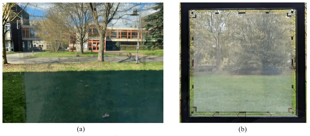
Figure 6. Images of a (30 × 30) cm2 sample: (a) View through a MEMS micromirror array after fabrication; (b) Window module (double insulation glazing, argon, spacers, butyl sealing) with integrated MEMS micromirror array. The mirror status is partially closed. Contacts for subfield addressing are visible (2 × 2 subfields). MEMS: microelectromechanical systems.
Our MEMS micromirrors arrays reveal long lifetimes, high reliability, large operating temperature range and are season independent. The following rapid aging tests have been performed on our MEMS smart glass: multiple fast extreme temperature cycles, long-term UV aging at variable temperatures, shock tests and mechanical vibration treatments over 26,000 h, long-term actuation at 4 kHz i.e. close to the resonance frequency (7 kHz) over twenty billion cycles, and operation at extreme temperatures down to -80 °C and up to 120 °C. Surviving these different tests, successfully, also shows a longer and stable maintenance free lifespan.
A comparison of all the smart window technologies based on material, functionality and fabrication process is presented in Table 2. Reducing the cost per unit area for all smart glass technologies and scaling up the manufacturing process of our MEMS smart glass will be one of the major challenges. To achieve sustainability goals, it is imperative to enhance the lifetime (durability) of PDLC, SPD, and electrochromic technologies. Furthermore, additional enhancements in terms of contrast (modulation depth), color fidelity, and switching speed are expected. It is more likely that the limitations associated with passive systems such as thermochromics and photochromics, particularly in terms of tailored daylighting, cannot be improved. Additionally, the large-scale implementation of microstructured films can be hindered by challenges related to process stability and polymer shrinking. Certain companies offering passive light steering systems or passive sun protection technologies contend that the requirement of continuous electricity is a drawback for PDLC, SPD, electrochromic, and MEMS technologies. We do not share this opinion since active technologies are superior to passive technologies by far, thus, reveal much more chances for smart personal environments, smart homes and smart green cities. The urgent requirement to reduce the CO2 footprint associated with human activities will push governmental bodies to implement distinct measures aimed at reducing the environment in our society. We believe that this will create a favorable environment for the adoption and growth of active smart glass technologies[57-61].
Table 2. Comparison of different surface technologies and materials used in different smart window technologies.
| Type | Technology | Active/ Passive | Material | Fabrication Technology | |||||
| TCO | Active Material/Top Electrode | Dielectr. | Sacrifi. Layer | ||||||
| Sun shading system | Photochromics [57,58,62-64] | Passive | - | WO3, TiO2, V2O5, Nb2O5, MoO3 | Azobenzene, spiropyran, furylfulgide, and diarylethene | CVD, Magnetron sputtering, Sol-gel with dip-coating, PVD, Electron-beam evaporation, Ion-beam sputtering, pulsed laser deposition, Vapour-phase deposition (sputtering). Sol-gel and polymer assisted deposition | |||
| Thermochromics [59,64,65] | Passive | - | VO2, TiO2, Ni2+, Co2+, Cu2+, Fe2+ chelates based metal complexes | ||||||
| EC[60,64,66] | Active | ITO, AZO, ATO | WO3, TiO2, Nb2O5, V2O5, MoO3 | ||||||
| Gasochromics[61,66] | Active | - | WO3 | ||||||
| MEMS Micro-blind[25,50 | Active | SnO2, ITO, Ag low-e | Shrinkable polymer with Al, NiCr, Cr, SiO2/Al | Polymer, SiO2, SiNx, Al2O3 | Photo-resist | Si, | UV photolithography, PECVD, Optical laser patterning, wet and dry etching, Evaporation, magnetron sputtering | ||
| LC systems | Polymer-Dispersed Liquid Crystal[61,67] | Active | ITO | Nematic LC droplets into polymer | phase separation - (i) PIPS, (ii) SIPS and (iii) TIPS, encapsulation method | ||||
| Polymer-Stabilized Liquid Crystal[61,68,69] | Active | ITO | Monomer, polyimide | PIPS | |||||
| Suspended Particle Device[61] | Active | ITO | Dihydrocinchonidine bisulfite polyiodide | Lamination process | |||||
| Light directing system | Prismatic panels[70] | Passive | . | OrmoComp, PMMA | Hot embossing or injection molding, UV-nanoimprint | ||||
| Sine-wave structure[71,72] | Passive | . | PMMA | Thermal compression molding | |||||
| Laser-cut structures[73] | Passive | . | Acrylic pane | Melting and ablation via laser | |||||
| Microstructured films[74,75] | Passive | . | Acrylic pane on PET | UV-nanoimprint | |||||
| MEMS Micromirror arrays[16,19,20,22-29] | Active | ITO, ZnO, SnO2, AlZnO | Al/Cr/Al | SiO2 | Photo-resist | UV photolithography, PECVD, optical laser patterning, wet and dry etching, evaporation, magnetron sputtering | |||
TCO: Transparent conducting oxide; CVD: chemical vapor deposition; PVD: Physical Vapor Deposition; ITO: Indium Tin Oxide; AZO: Aluminum-doped Zinc Oxide; ATO: Antimony Tin Oxide; UV: Ultraviolet; PECVD: plasma-enhanced chemical vapor deposition; LC: liquid crystal; EC: electrochromics; PIPS: Positive Ion Probe Surface Spectroscopy; SIPS: Surface Ion Probe Spectroscopy; TIPS: Thermal Ionization Probe Spectroscopy.
2.3 Global impacts
Due to the prevalent energy inefficiency in the majority of building structures, the building sector offers the second most significant opportunity for energy savings, surpassed only by the energy sector itself. The urgent need to reduce CO2 emissions resulting from residential and commercial activities has spurred public attention towards taking distinct action in energy savings, which involves the adoption of energy-efficient technologies in new construction and the replacement of outdated and inefficient appliances in existing buildings. Initiatives such as the European Green Deal, which are focused on sustainability objectives like “Building and renovating in an energy and resource-efficient way”, lay particular emphasis on the building and construction sector and addressing the imperative of renovating both public and private building stock to incorporate energetically efficient and resource-conscious housing solutions. Integrating digital technologies and climate-proofing tools is necessary to enhance overall performance. Furthermore, emerging technologies must guarantee essential energy services to ensure a basic standard of living for all citizens at an affordable cost, thereby combatting energy poverty. These principles align with the objectives outlined in the New EU Directives on Energy Performance of Buildings (2018), which aim to achieve a low and zero-emission building inventory in the EU by 2050. This ambitious goal is boosted by the integration of smart technologies. Another core sustainability objective of the European Green Deal is the implementation of a zero-pollution ambition and creating a toxic-free environment. The substantial reduction in energy consumption within buildings will certainly result in a decrease in greenhouse gas emissions.
Smart window technologies, despite their limitations and drawbacks, have the potential to deliver substantial energy savings by harnessing daylight and solar heat. Sun shading window technologies, for instance, can result in energy savings of approximately 22% compared to standard double-glazed windows[15]. Our MEMS smart window, specifically, has the capacity for significant energy conservation, amounting to a remarkable 2,240 TWh in the EU alone. This translates to a reduction of 339 Mt of CO2 emissions[16]. The urgency to mitigate CO2 emissions, coupled with the promise of these emerging technologies, will drive the advancement of surface technologies, particularly in the scope of smart glass.
2.4 Current and future market trends
The continuous rise in energy consumption, driven by extensive demands across various sectors, particularly in the building sector, accounts for approximately 50% of final energy consumption and contributes to 33% of greenhouse gas emissions. The European Commission (EC) has reported that a significant number of buildings were constructed prior to the first thermal regulations in 1970, rendering them energy-inefficient. Furthermore, as of 2020, existing buildings already make up 70% of the building stock that will be present in 2050.
Research has revealed[9] that around 70% of the buildings in the European Union are more than 30 years old, with 35% exceeding the 50-year mark. Considering these unavoidable circumstances and the positive public reception of energy-efficient household appliances, as demonstrated in numerous studies, implementing energy-efficient retrofit has yielded mixed results due to the high initial investment and a slow turnover rate. However, smart window technologies, particularly our micromirror array-based windows, are regarded as one of the most promising solutions that can be applied to existing buildings. This is attributed to their lower acquisition cost and high potential for energy savings.
As per various business analytics reports, the Global Smart Glass Market is projected to reach a value of $14.05 billion by 2032[76], demonstrating a robust CAGR of 10.8% (2023-2032)[76]. This growth is primarily fueled by escalating political pressures promoting building renovations and the incorporation of smart green building and city concepts. These factors are expected to boost our product sale in both new and existing building stocks. Furthermore, there is a growing preference for technical energy-saving measures, such as house insulation and energy-efficient products, over strategies that involve minimizing resource usage. Consequently, the adoption of smart glass in building applications is expected to experience accelerated growth in the coming years. Smart glass is assessed to capture a significant share of the future window market, driving substantial advancements in surface technologies.
The intelligent control of light, room temperature, and humidity is set to become a central focus in the development of future building technologies. This approach aims to mitigate heat losses, harness solar heat, and provide occupants with natural lighting, which has a positively impacts on human health, happiness, and overall well-being.
3. Simulation of Light Steering Inside a Model Room Using MEMS Micromirror Smart Glass
The lighting situation within a room is composed of natural and artificial lighting in certain proportions, depending on individual brightness requirements. Regarding sustainable and energy-efficient building design, the use of available natural solar resources is becoming increasingly important[77]. In order to investigate daylight-steering via MEMS micromirror arrays, we already used analytical calculations and ray tracing simulations back in 2015[78]. The focus of that work was, among others, the development of an analytical model for the computationally efficient simulation of daylight deflection of 1D micromirror arrays. Beyond these investigations we improved the ray tracing simulations, considerably regarding flexible user positions combined with the correlation of the distinct addressed light spot sizes at the ceiling above the users and the angular distributions of the brightest areas in the sky. Since the micromirrors are divided into subfields that can be controlled independently of each other and tilted at different angles, an optimum personalized and individual lighting situation can be achieved[23,79]. Within this article, we will present the methodology for determining the required angular positions of the micromirrors for all subfields, the creation of the simulation models and point-in-time simulations in a model room to investigate the amount of light that can be achieved by light steering quantitatively. Our considered scenario comprises a model room with four windows (137.9 × 81.3) cm2, a vertical wall part of 77.1 cm (above) and 85 cm (below), respectively, a room height H = 3 m, a room width W = 4.5 m and a room depth D = 8.3 m (Figure 7). The window is south oriented, and we consider noon daytime on June 21st. For simplicity, only 1D actuation is considered. Note that via adequate 2D light steering, other window orientations and other day- and season-times can also be easily put into consideration.
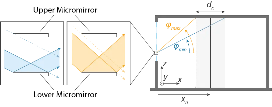
Figure 7. Geometry of the model room with a visualization of the light cone, further notations, and reflection and transmission behavior through the micromirror array smart glass. Reproduced with permission from[28].
3.1 Angular position determination
An efficient use of our MEMS micromirror smart glass as a light steering system requires an adequate control system that automatically optimizes the lighting situation depending on the actual environmental parameters at that particular moment. Both indoor and outdoor conditions must be considered for the control process. For optimum control, a compromise must be made between the maximum possible illumination (to save artificial lighting) and simultaneous minimum heating (to save air conditioning) of the room. A crucial factor for this trade-off is the information about the presence of people in the room, since only in this case it is necessary to prioritize the lighting of the room. If no users are present in the room keeping the room cold will be prioritized in hot summer days, whereas harvesting as much as possible solar radiation and heat will be prioritized in winter. In the following, the procedure for determining the mirror angles will be presented, focusing on optical optimizations without reporting the involved additional thermal influences.
Since the micromirror arrays are a light steering system, the user benefits from the resulting diffuse scattering of light from the ceiling, which is initially redirected by the micromirrors to the room ceiling above the user. To perform such controlled light steering, the first step is to detect the position xu of the users in the room. In the general case, i.e., 2D light steering, the x- and y-coordinates of the people in the room are recorded. In the 1D case, considered here for simplicity, the determination via the x-coordinate is sufficient since the light deflection (ray tracing) mainly varies in the xz-plane. According to Figure 7, the detected x-coordinate of the user position xu is the target position of the center of the “light cone”, which is spanning the distance dc at the ceiling. The smart glass with the micromirror arrays includes multiple subfields, which are arranged in rows and columns, where the mirrors in each subfield, are tilted identically. For each subfield, the relative position to the projected light cone varies in z-direction. As a result, an individual angular configuration must be calculated for each subfield. Due to the borders of the projected light cone, an individual acceptance angle pair φmin and φmax can be derived for each subfield, under which the incident light contributes to the angular intensity profile inside the light cone. Thus, the objective is to align the micromirrors so that the luminance is maximized for the incident light angles within the spanned distance dc. For this purpose, it is necessary to determine those angles of incidence of the sky from which the highest luminance emanates (brightest areas in the sky, in short). In addition, the angle-dependent transmission and reflection properties of the micromirror array must be considered since only those angles originating from sky regions with high luminance can effectively contribute to light cone formations. In order to systematically perform this optimum angle search (for the 1D steerable micromirrors), a two-step ray-tracing script was written to determine the angle-dependent transmission properties of the micromirror array by brute-force search. This is performed for all feasible angular positions, first in the forward and then in the backward direction. Based on the obtained results, the optimum angular mirror tilt of a subarray is determined, in consideration of the existing angle-dependent luminance in the sky. These serve as input parameters for the daylight ray tracing simulations described later to show the potential of light steering based on three lighting scenarios. Note that the sky’s brightness varies abruptly in case of direct sun incidence or sharply bordering white clouds. However, during overcast days the brightness can vary softly, providing no sharp cone borders. Soft borders of the light spot at the ceiling are desired and will additionally appear by very small deviations from 100% planar mirrors (minor curling or mirror surface roughness).
3.2 Complex fenestration system (CFS) modelling
A complex fenestration system implements advanced window architecture, applying special technologies. Such a system aims to optimize light conditions in a room by means of light shading, guiding and redirection, refraction or even further phenomena[80]. The characterization and physical modelling of complex fenestration systems can be difficult and vary in procedure from case to case[81,82]. The optical transmission characteristics, based on the angle-dependent transmission and reflection behavior, can be described using a so-called bi-directional scattering distribution function (BSDF)[83]. A BSDF in the field of daylighting simulations represents a data-based and discretized function of the visible and solar reflectance and transmission properties of a window system that can be used in terms of simulations. The determination of that BSDF can be performed physically by the angle-dependent measurements of a real sample using a photogoniometer or virtually based on a ray tracing method using the modelled geometry of the CFS and its materials[81,82]. Since no complete measurement data for the physical modelling of the BSDF of the described micromirrors are available so far, a BSDF generated via ray tracing is used in the context of this work. For this purpose, the validated light simulation software Radiance[84] is used, which generates a BSDF with a user defined resolution as a low-resolution Klems BSDF or high-resolution Tensor Tree BSDF using the genBSDF tool that is included in Radiance. For the following workflow, both Klems and Tensor Tree BSDFs are used. To create the models considering thermal behaviour, Klems BSDFs with an angular resolution of 13.5° are used (according to the 145 × 145 subdivisions per incoming and outgoing hemisphere) since a high angular resolution is not necessary for these simulations. However, for the optical simulations, Tensor Tree BSDFs with an angular resolution of 2.53° (according to the 4,096 × 4,096 subdivisions per incoming and outgoing hemisphere) are used to represent the high specular reflection effects of the micromirrors during light steering in reasonable accuracy[85]. Even though it is possible to create Tensor Tree BSDFs with much higher angular resolution, they require substantial computational effort, so the chosen angular resolution is a compromise between acceptable computational time and sufficient accuracy according to the dimensions of the model room. For the generation process of the BSDFs, a 3D CAD model of the system to be characterized is required. This model is created using the computer-aided design software Rhinoceros[86] and the plugin Grasshopper[87] for parametric modelling. To investigate the influence of different angular positions of the micromirrors on the simulations, it is necessary to model a corresponding geometry for each angular configuration under investigation. For this purpose, models are created for all tilt angles Φ of the respective subfields required to create a light cone at user position xu (Table 3).
Table 3. Angle determinations for optimum light steering for a user position of xu = 2 m, 4 m and 6 m.
| Smart Glass Subfield | |||||||
| xu | 1 | 2 | 3 | 4 | 5 | 6 | 7 |
| 2 m | 20° | 17° | 15° | 13° | 11° | 10° | 8° |
| 4 m | 25° | 24° | 22° | 21° | 20° | 19° | 18° |
| 6 m | 27° | 26° | 25° | 25° | 24° | 23° | 22° |
Subfield 1 is the topmost and 7 is the lowest subfield in the z-direction.
Since the angular resolution of the Tensor Tree BSDFs used is limited to 2.53°, this implies that the results may deviate slightly from the achievable optimum. However, they should be sufficiently accurate to show the achievable effects in the model room. Since both optical and thermal simulation model of the micromirror array has to be created, which can describe the behavior over the relevant wavelength range from 400 nm to 2,500 nm of the electromagnetic spectrum, the geometrical models additionally require an assignment of realistic material properties of the micromirror array. For this purpose, the reflection and transmission spectra of the micromirror metallic stack are determined via the open-source software OpenFilters[88] by modelling the multilayer system of the micromirrors to obtain the required values for the material assignment. As expected, the transmission spectrum of the metals is nearly zero over the considered wavelength range, as shown in Figure 8. The reflection shows a profile that is characteristic of aluminum. Subsequently, the colorimetric properties of the metallic layer system for a correct color rendering of the reflected light are determined by standardized colorimetric methods using the CIE standard illuminant D65, the CIE standard observer CIE-1931 and the reflection spectrum of the layer system using OpenFilters. The calculated L*a*b* color values can be converted to equivalent RGB color values that can be processed by Radiance. For the sake of simplicity, the layers of FTO and silicon dioxide are neglected in the description of the material properties. The specularity and roughness values were assumed to be optimum according to the high-quality technological processes used to fabricate the layers.
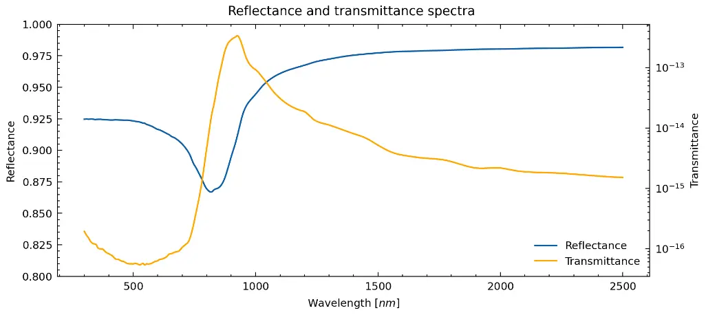
Figure 8. Simulated reflectance and transmittance spectra of the modelled metallic multilayer system. Reproduced with permission from[28].
Based on the considered geometries and its material definition, genBSDF is used to generate both a low-resolution Klems BSDF and a high-resolution Tensor Tree BSDF that can be used to describe the visible and infrared reflection and transmission properties of the micromirror array. Since the Tensor Tree BSDFs are generated for the micromirror element combined with the glazing using genBSDF, the Klems BSDFs, however, are generated only for the micromirror element without the glazing. Therefore, the generation of the Klems BSDFs of the entire CFS is done using the open-source software WINDOW 7.7 from Lawrence Berkeley National Laboratory[89]. In this process, a glass system is added to the already generated Klems BSDFs that represents the micromirror system and the thermal material properties are added beforehand. These include the thermal conductivity of the materials, the thermal emissivity of the front and back sides of the metallic micromirrors, and the thermal infrared transmissivity Tir (Table 4).
Table 4. Material properties for WINDOW 7.7 calculations.
| Parameter | Value |
| Thermal conductivity [W/m × K] | 237.0 |
| Thermal emissivity, front [%] | 0.00019 |
| Thermal emissivity, back [%] | 0.00019 |
| Infrared transmission Tir [%] | 1.27•10-13 |
The value for Tir was determined as an average value based on the transmission spectrum of the aforementioned layer system created with OpenFilters over the wavelength range from 750 nm to 2,500 nm, while the values for the thermal conductivity and the thermal emissivity were taken from literature[90,91]. Although only daylight simulations are considered below, a model with thermal material properties is created since the thermal transmittance (Ug-factor) and solar heat gain coefficient (g-value) of the window model can be calculated within WINDOW 7.7 next to the visible transmittance (Tvis), so that these can be used with regard to future thermal simulations. While Tvis and g-value are calculated integratively over all outgoing light angles for incoming light at normal incidence, the Ug-factor is determined based on ISO 15099 defined calculation standard for shading devices[92]. The fenestration system, in which the micromirror array is to be integrated, is a quadruple glazing (QG), as shown in Figure 9 with the properties mentioned in Table 5 and corresponds to that of the demonstrator described[19,20]. QG was chosen due to the current trend towards insulation glazing with a higher number of panes. Additionally, the stronger ray spreading in QG increases the complexity of the simulation and makes direct transfer of the results from double to QG inadequate. The thickness of the micromirror material is negligible (maximum extension is 150 μm in the x-direction) in comparison to that of glass and argon filled gap, thus, ignored in the calculation. To exclusively consider the influence of the micromirror array on the improvement of the CFS properties, the integration of a low-e coating within the glazing structure is omitted. Due to the high sensitivity of the micromirror arrays to moisture, the inert gas atmosphere used in the interpane cavity is 100% argon due to its low heat conduction (monoatomic gas has minimum degrees of freedom). Table 6 shows the previously mentioned properties for quadruple glazing as a reference and for a glazing system with micromirrors for completely open (0°) and closed (90°) tilt angles, as well as averaged values for all other tilt angles used between 1° and 30° for the sake of simplicity, since these show only slight deviations. When considering Tvis exclusively through the quadruple glazing, about 65% of the incident light is transmitted through the glass. On the other hand, integration of micromirror array will result in additional transmission losses of about 5-10% due to the micromirror structure, depending on the tilt angle. Even though the quadruple glazing already provides an efficient insulation performance with a Ug-factor of 1.16, this property can be even improved further by almost 35% through the integration of the micromirror arrays by achieving a Ug-factor of 0.76. Likewise, compared to the reference glazing, the g-value can be improved by 7-12% depending on the tilt angle up to 30° and even by 86% to a g-value of almost 0 for the complete closing of the micromirrors. This shows that by modulating the g-value through the opening and closing of individual subfields, it is possible to control the occurrence of solar emitted infrared radiation in order to specifically adjust the heating of the room.
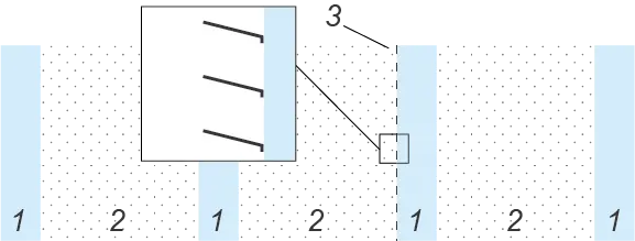
Figure 9. Glazing structure of the CFS with micromirrors (the left side faces the outside; the right side faces the inside of the room). Reproduced with permission from[28]. CFS: complex fenestration system.
Table 5. Thickness of the materials used in the CFS.
| Layer | d [mm] | |
| 1 | Generic clear glass | 3.912 |
| 2 | Pure argon | 16 |
| 3 | Micromirror structure | - |
CFS: complex fenestration system.
Table 6. Optical and thermal properties of the CFS.
| Tvis | Ug-factor | g-value | |
| QG | 0.65 | 1.16 | 0.59 |
| 0° | 0.60 | 0.76 | 0.55 |
| 1°-30° | 0.55 | 0.76 | 0.52 |
| 90° | 0.00 | 0.76 | 0.08 |
CFS: complex fenestration system.
3.3 Daylight ray tracing simulations
The potential for the yield of daylight that can be achieved with the help of our micromirror smart glass will be introduced in the following using the example of a model room under consideration of different user positions in room depth (x-direction) as target position in light steering. The modelling of the room is also performed with Rhinoceros and Grasshopper. The daylight simulations are performed within the modelling environment of Rhinoceros and Grasshopper using the plug-in Ladybug Tools 1.5.0 (contains Honeybee for daylight simulations). Ladybug Tools[93] is a simulation environment that provides comprehensive building simulation based on various validated simulation engines (Radiance, EnergyPlus, OpenStudio, etc.). To investigate the modelled CFS, the window apertures of the room model are assigned with the previously generated BSDFs, as well as with a reference glazing based on the identical glass system. The daylight simulations performed in Honeybee as a part of this work are also based on Radiance, so appropriate simulation parameters must be chosen to perform the simulations.
The simulations’ design performed is based on a 4.5 m × 8.3 m × 3 m model room (further properties are listed in Table 7). The orientation of the installed windows is chosen in geographic south orientation. The location of the model room for performing the simulations is at a mid-latitude in Europe in the center of Germany (Kassel, 51°19′0′′N, 9°30′0″E).
Table 7. Detailed model room properties.
| Parameter | Detail |
| Room size | Width: 4.5 m; Depth: 8.3 m; Height: 3.0 m |
| Window orientation | South |
| Surface diffuse reflectance | Ceiling: 80 %; Wall: 50 %; Floor: 20 % |
| Grid height | Work plane: 0.85 m |
| Ceiling: 3.00 m |
The strength of the micromirror based smart glass lies - next to the improvement of the Ug-factor and modulation of the g-value of a window glazing - in its dynamic control of daylighting, allowing it to be directed to a desired position in the room. A point-in-time simulation is performed based on a CIE standard clear sky to simulate this behavior. The simulation time is June 21st at 12 noon in the previously described model room. According to the sun’s position at a considered daytime, the angles with the highest luminance are at altitude of 61.8° and azimuth of 168.3°. Following the calculation procedure described above, the optimum angle configurations for three different lighting scenarios are derived and shown in Table 3. Those three simulated scenarios vary with respect to the user’s position xu = 2 m, 4 m or 6 m. At that position the user is illuminated via a light spot location xu at the ceiling. To check the lighting situation generated, the illuminance on the work surface and ceiling is shown as a function of the horizontal x-coordinate directed into the depth of the room, respectively as shown in Figure 10.

Figure 10. Illumination distribution due to light steering by our micromirror smart glass for a user position xu = 2 m, 4 m and 6 m and by the reference glazing (QG) without micromirrors. Note that the work plane is 85 cm above the room floor. Reproduced with permission from[28]. QG: quadruple glazing.
This figure displays the illumination distributions on both the work plane and the ceiling, with and without micromirror smart glass inside a QG. The shift of the brightness maxima at the room ceiling, caused by the shift of the user’s position xu, can be clearly seen from the illumination of the work surface by means of diffuse scattering. It is particularly noticeable that the brightness maximum of almost 30,000 lx on the work surface is directly at the window when the glazing without micromirrors is used. With the use of micromirrors, on the other hand, this unused light is steered onto the room ceiling so that the diffuse reflection of the light cones in all three cases provides an illuminance of at least 2,000 lx to 3,000 lx on the work surface below the light cones. For the case xu = 6 m, the illuminance does not fall below 1,000 lx even over the entire length of the room. Since the tilt angles of the micromirrors were calculated exactly for the x-coordinates mentioned for the different scenarios, a slight deviation between the light cone maxima and the intended target position can be seen, which is in the range of 20-30 cm. These deviations can be caused both by the fact that the angular resolution of the Tensor Tree BSDFs is not optimum, thus the required angles cannot be resolved sufficiently; and that the calculation of the required tilt angles is limited to integer values, which always results in a slight deviation that is especially noticeable at higher room depths. For a more descriptive 3D consideration of the model room under the three different lighting scenarios, these are visualized in Figure 11 as rendered images with an indication of the locally existing brightness distributions. Based on the brightness contour lines within the room, the influence of the controllable light cones on the entire room can be assessed more clearly. Since the sun is not exactly in the south direction (latitude 180°) at the observed time at the location carried out with latitude 168.29°, this can be recognized by the slight extension of the light cone on the wall which is in the background in Figure 11. This is a lateral displacement that cannot be compensated with the 1D tilt angle, which consequently validates the necessity of the previously presented 2D actuatable micromirrors to guarantee optimized control for arbitrary sun positions. Further improvement of flexible daylight steering including 2D actuation will be part of future work and will reveal greater potential of our MEMS micromirror smart glass technology, allowing active light steering independent of the window orientation, the season, the daytime, and the user movements.
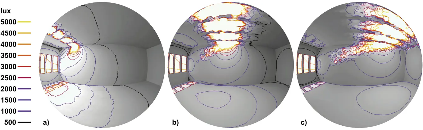
Figure 11. Rendered images in fish eye lens perspective from inside the model room to view the overall impression of the illumination distribution considering the generated light cones at xu = 2 m (a), 4 m (b) and 6 m (c). Reproduced with permission from[28].
Different user actions require adequate illuminance. Bureau working places, including writing and data processing require 500 lx. If technical drawings by hand are included, 750 lx is the minimum requirement. As for the workshop and working place of opticians, 1,500 lx is prescribed. However, if the room usage simply involves walking inside the room, less than 500 lx is sufficient. For example, warehouses should be illuminated with 100 lux. This is sufficient to orient oneself, to find stored goods quickly and safely, and to make them available quickly if necessary. The standard also stipulates that, e.g., 300 lx should be achieved in shipping.
This means we are by far above the required illuminance in many use cases as per the result in Figure 10. By using less subfields, we can locally reach the required light conditions by far and save more energy, for example in summer. We will focus on this field in our future work, and we will also integrate 2D actuation in our simulations.
Furthermore, a completely homogeneous ceiling illumination is possible, using adequate cooperation of all the subfields in daylight steering via our smart glass. This is a very attractive scenario in winter, e.g., when we wish to harvest the whole available visible, near and mid infrared solar radiation, in order to save energy for heating. Note that visible and near-infrared (solar infrared) is converted into heat (mid infrared) after the electromagnetic radiation has been absorbed by any objects inside the room. In summary, a challenging and interesting working field lies ahead.
4. Energy Saving and Amortization Times
The energy savings and amortization time simulation is carried out in two steps depending on the weather database, electricity price and engine class reduction for MEMS smart window in comparison to a window with conventional tiltable aluminum blinds. Firstly, comparatively lower electricity prices and constant engine class reduction are used along with the Test Reference Year (TRY) database generated from the observation of previous years for Kassel, and secondly, the simulation is conducted for four different cities in Germany (Konstanz, Winterberg, Kassel and Flensburg) considering an increased electricity and equipment price, varied engine class reduction, actual and future predicted TRY database. A comparison of the amortization is made in relation to the available historical data (2014-2019) and future predicted TRY data. Furthermore, the simulation extends to two cities outside of Germany, namely Qingdao, China, and Riyadh, Saudi Arabia, using historical data covering the period from 2014 to 2019.
4.1 Energy savings and amortization time calculation for Kassel, Germany
4.1.1 Room scenario and investment
Maximum utilization of sunlight and limiting the requirements of space heating, air conditioning and artificial lighting that leads to energy saving is the principal aim of micromirror-array-based smart windows. Consequently, window orientation plays a crucial role depends on the location and sun’s position in the sky during the course of the day in different seasons. In order to face the sun and utilize the maximum solar radiation, windows must be south-oriented in the northern hemisphere, or the opposite in the case of the southern hemisphere. The sun position throughout the day in winter, summer, spring and fall for the stated room condition is illustrated in Figure 12. During summer, the sun rises in the northeast and sets in the northwest, following a high and lengthy path in the sky at solar noon during the summer solstice. Furthermore, the northern hemisphere tilts towards the sun in the summer, resulting in extended daylight hours and intense heating from the sun’s overhead position. In contrast, during winter, the sun rises in the southeast and sets in the southwest, following a shorter trajectory and reaching a relatively lower point in the sky at noon. During the winter solstice, the hemisphere tilts away from the sun, resulting in shorter daytime hours and colder weather. The sun’s path remains in between these two stated extreme positions during other times of the year.
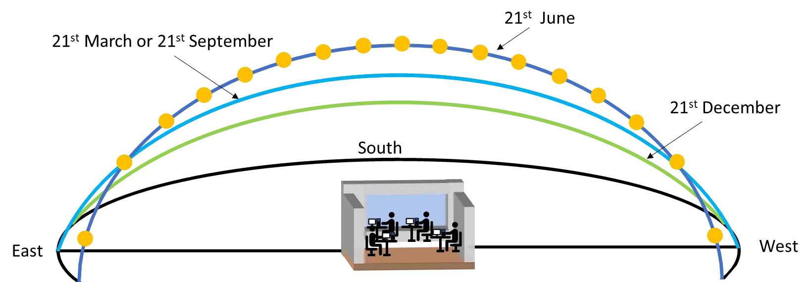
Figure 12. The sun’s path with respect to an office room located in the northern hemisphere for winter, summer and spring and fall. Reproduced with permission from[16].
An office room with dimensions of 12 m length, 8.3 m width and 3 m height on the sixth floor of a commercial building in Kassel, equipped with a triple insulation windowpane having dimensions of 12 m length and 3 m height, covering the whole area of a south facing wall, is considered. The office room is occupied by 20 persons and furnished with 10 tables, 20 chairs, 20 computers, 20 mobile phones and 10 cupboards. It is important to note that in the model calculations, the occupants perform identical activities throughout the working hours all over the year. The manufacturing and installation cost of a 36 m2 normal window as well as the operating cost of micromirror arrays (module including manufacturing and installation) and window with aluminum blinds (including motor, controller, adapter and interfaces) are considered in the calculation. The maximum energy saving we would obtain comparing windows without any blinds and with windows having MEMS smart glass. However, we aim to adopt a moderate approach and engage in scenario simulations that steer away from excessive optimism. The second reason is that a large number of windows today have external or internal blinds or externally installed light shades, and it might be interesting for the readers.
The price of normal triple glazing window and window equipped with aluminum blinds are considered to be 550 €/m2 and 800 €/m2. Note that MEMS smart glass can be supplied according to customer requirements in different categories from standard to premium and in different price ranges. For the simulations an average cost of 1,550 €/m2 has been considered. This is the average cost ranging from standard to premium embodiment of the window.
In MEMS smart windows, tailored light guiding is possible due to the development of sub-field addressing in micromirror arrays[23], thus the whole window module is segregated into 36 subfields, each having 1 m2 area. A constant temperature of 20 °C and 500 lx of illuminance per m2 is maintained in the room by the required lighting, heating, and air-conditioning appliances (Table 8).
Table 8. The specification for light, heater and air conditioner requirement for the room.
| Specification | |
| Light fixtures | 49800 lm |
| Heater | 10720 W |
| Air conditioner | 5.3 t |
The electricity cost per kWh is assumed to be 0.40 €[94]. Based on the requirement as mentioned above for the model room, the initial investment on the lighting, heater and AC is considered to be 21,186 €, 24,300 € and 31,250 € respectively with window blinds and 18,000 €, 22,599 € and 27,500 € respectively with MEMS smart window. Since MEMS smart window enables proper distribution of daylight and solar radiation, the engine power (The wording “engine power” means “engine size” or “engine class”) for light, heater and air conditioner is reduced by 15% compared to the windows equipped with aluminum blinds. Due to the energy saving capacity of MEMS smart glass, the engine class does not need to be as large as for window with aluminum blinds. The simulation results without any engine class reduction as well as several combinations of engine class reduction have been presented[16]. Since we simulated a potential to save up to 35%, we chose a reduction value which is moderate in comparison to 35%. We are aware that by using another combination of the multiple input parameters, we would obtain a different simulation result. We cannot simulate and report on all possible combinations. In a proper scientific way, we provide all the used input parameters.
A TRY database is used in our calculation for Kassel, located at 51.18° N latitude, 231 m above the sea level and in the central area of northern, western and eastern low mountain ranges (up to 600 m above sea level). The database is a combination of hourly data for Kassel over the year from January 1st to December 31st recorded by the “Deutscher Wetterdienst” (German Metrological Service) from a considerably long observation period of 1995-2012. The meteorological parameters of the database are listed in Table 9. The data like temperature, cloud coverage, heat irradiance, visible irradiance, wind velocity and others are permanently recorded. Still, for all parameters, an averaged value has been saved each hour (henceforth referred to as hourly data). The methodology of the data construction in the TRY database considering a long period of time is described in EN ISO 15927- 4:2005[95].
Table 9. The climatic parameters recorded in the TRY database with corresponding units.
| Parameter | Unit |
| Degree of cloud coverage | okta |
| Wind direction at a height of 10 m above ground | ° |
| Wind speed at a height of 10 m above ground | m/s |
| Air temperature at 2 m above ground | °C |
| Air pressure at station height | hPa |
| Water vapor content, mixing ratio | g/kg |
| Relative humidity at a height of 2 m above ground | % |
| Direct solar irradiance (horizontal plane) | W/m2 |
| Diffuse solar irradiance (horizontal plane) | W/m2 |
| Atmospheric heat irradiance (horizontal plane) | W/m2 |
| Terrestrial heat irradiance | W/m2 |
TRY: Test reference year.
4.1.2 Calculation methodology
The sun’s position in the sky with respect to an observer can be fully determined by two astronomical angles, solar altitude angle and solar azimuth angle. Solar altitude angle is defined as the angle between two imaginary lines from the sun to the window and the horizontal plane of the window location. This angle effectively determines the elevation of the sun in the sky. The altitude angle is correlated to the solar zenith angle and can be calculated by the equation,
where
α = altitude angle,
L = latitude angle,
h = hour angle,
φ = solar zenith angle,
δ = declination angle
n = 1 for January 1st,
n = 1 for January 2nd,
t = number of minutes from the solar noon.
The value of altitude angle (α) increases from zero in the morning, reaches its maximum in the solar noon—indicating the highest sun position in the sky and decreases to zero again in the evening. Incoming radiation from the sun is typically calculated when the altitude angle is higher than 0°, which is considered a reasonable approximation.
The solar azimuth angle (z) represents an indicator of how much the sun deviates from the due south direction in the northern hemisphere and from the due north direction in the southern hemisphere. It provides information about the horizontal direction in which the sun is located relative to a specific position of the observer on the Earth.
This equation is only applicable for the condition cos(h) > tan (δ)/tan (L). The incident angle characterizes how the sunlight strikes the window surface and determined as the angle between a perpendicular line on the window plane and the incoming light rays from the sun. The general expression for the incident angle[96] is
where
β = surface tilt angle from the horizon,
Zs = surface azimuth angle, the angle between the normal to the surface from the true south.
Since the window in this calculation is vertically oriented, the surface tilt angle (β) is considered to be 0°. Therefore, equation 3.5 is reduced to
Indeed, the solar incident angle gradually decreases in the morning and reaches its minimum value at solar noon. As a result, during solar noon, the window surface receives solar radiation with the least divergence from a perpendicular vector. This means that at solar noon, the sunlight hits the window surface most directly, which can have implications for maximizing energy capture or minimizing shading effects[97,98]. The schematic representation of solar angles with respect to the south-oriented window is depicted in Figure 13. For simplicity, this calculation includes only eight different orientations, representing a range of possibilities including south, southwest, west, northwest, north, northeast, east, and southeast, by accurately determining the surface azimuth angle, denoted as Zs in equation 3.6. Depending on the surface azimuth angle, any desired window orientation can be achieved:
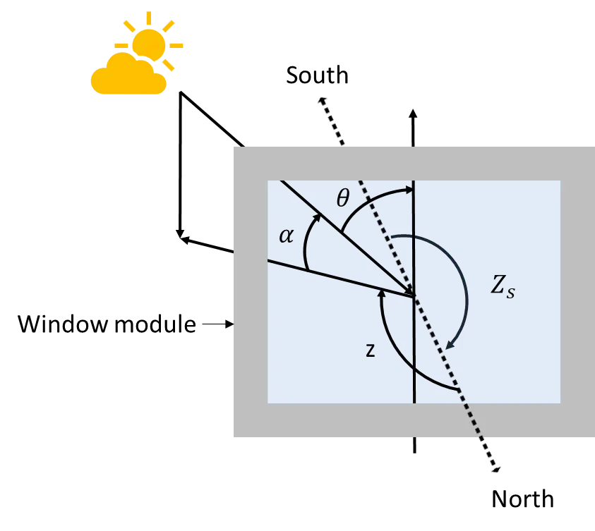
Figure 13. Angles to define the position of the sun with respect to a window module for a south-oriented window. Reproduced with permission from[16].
• Zs = 0° for south orientation,
• Zs = 45° for southwest orientation,
• Zs = 90° for west orientation,
• Zs = 135° for northwest orientation,
• Zs = 180° for north orientation,
• Zs = 225° for northeast orientation,
• Zs = 270° for east orientation,
• Zs = 315° for southeast orientation.
The total solar irradiance falling on the window is calculated from the TRY database by using the following equation,
where
Idirect = direct solar irradiance,
Iatm = atmospheric heat irradiance,
Iearth = terrestrial heat irradiance,
Idiffusion = diffuse solar irradiance,
N = degree of cloud coverage.
The analysis of light interactions at each interface of the triple-pane window takes into account the fractions of light that are reflected at the interfaces, which is referred to as angular reflectance. The Fresnel equations were reduced by formulating the transition equation of electromagnetic wave at the interface to determine the visible light transmission. Fresnel equations are dependent on the incident angle, relative refractive index of the interface and polarization of the incident light. Light polarization is categorized based on the orientation of the electric field. Given that angular reflection varies depending on the orientation of the electric field with respect to the window interface plane, the parallel (p) and perpendicular (s). Moreover, the p and s polarizations can be described by the parallel and perpendicular oscillation of the electric field[99]. In a triple plane window, incident light has to pass through six interfaces (air-glass, glass-argon, argon-glass, glass-argon, argon-glass, glass-air); the angular reflection is calculated at all the interfaces in Figure 14 using similar equations like (3.8) and (3.9).
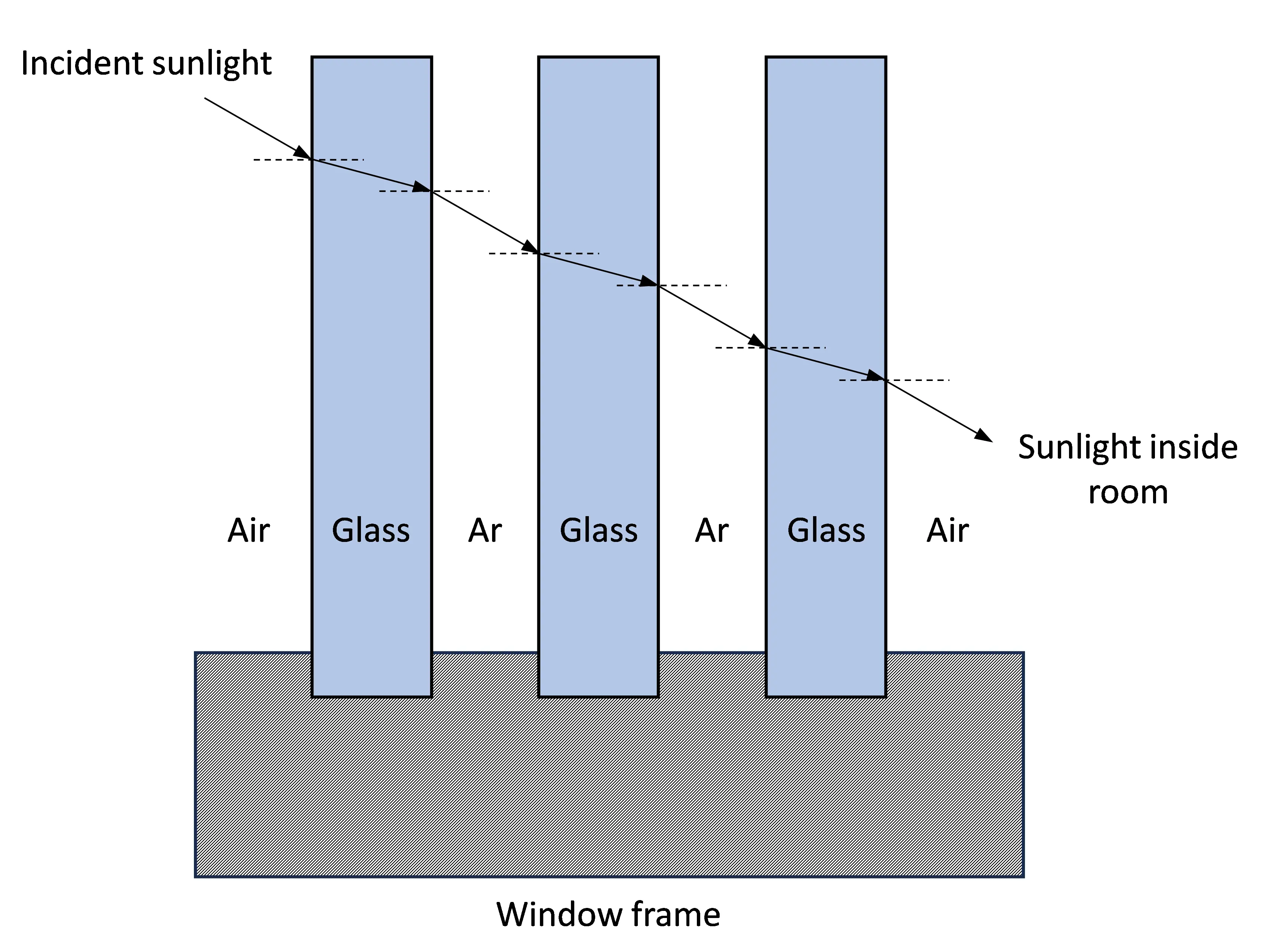
Figure 14. Illustration of light travel path at every interface in a triple glazing window having argon (Ar) in the window spacing. Sunlight travel paths at the interfaces are represented by the arrows. Reproduced with permission from[28].
As an example, the angular transmission at the argon-glass interface is explained here,
where
Rp(argon-glass) = angular reflection for p light at argon-glass interface,
Rs(argon-glass)= angular reflection for s light at argon-glass interface,
ns(argon-glass)= relative refractive index at argon-glass interface.
The initial incident angle is calculated for each hour over the course of the year, representing the angle at the first argon-glass interface. However, as light travels inside the windowpanes the incident angle changes. Therefore, Snell’s law is used to calculate the incident angle at the interfaces before the sunlight reaches inside the room,
Where θ2 is the refracted angle of sunlight while passing through the argon-glass interface. Since the sunlight produces unpolarized light and it contains same quantity of p and s polarizations, the angular reflectance is therefore approximated by taking the average of the two polarized angular reflectance coefficients.
It’s worth noting that there is no absorption of light within each pane. Therefore, when considering refraction, the total angular light transmittance through the argon-glass interface can be calculated as follows:
A low-e coating on a window filters out specific portions of the near-infrared and mid-infrared wavelengths, allowing only a specific band of the solar spectrum to pass through. The solar spectrum is demonstrated in Figure 15a, which reveals the black body radiation of the sun attenuated by the spectral absorption of different molecules in the earth’s atmosphere, such as water, nitrogen, oxygen, carbon dioxide, argon and others. The solar irradiance that passes through the window into the room is determined by using the low-e profiles depicted in Figure 15b. Low-e coatings (low emissivity) consist of up to 35 different ultrathin dielectric layers and a silver layer which also varies in thickness (about 5 nm thick). 5 nm silver is transparent for visible light but reflects mid infrared electromagnetic waves. Due to the design of all thin-film layers, it can reflect or transmit more or transmit less near infrared light. In our manuscript we consider three different configurations which are often used. High solar gain glass harvests much more near infrared light than low solar gain glass. These properties are tailored by the individual layer thicknesses and materials.

Figure 15. (a) Experimental solar spectrum presenting the irradiance and (b) transmission profiles for low (green), high (blue) and moderate (red) solar gain low-e coating as a function of wavelength. Reproduced with permission from[16]. low-e: low-emissivity.
Note that the low-e coatings can be designed for winter or summer: (i) in countries having long and very hot summers and no cold winters, the design for optimum summer performance is used. Consequently, the chosen design is not ideal for the winter, but in this case more energy for air-conditioning is saved in summer than additional heating energy is required in winter; (ii) in countries which have longer and cold winters, the design for optimum winter performance is used. Therefore, the chosen design is not ideal for the summer. However, in this case more energy for heating is saved in winter than additional air-conditioning energy is required in summer. In Germany, the low-e coatings are optimized for the winter.
The transformation of near infrared light (also called solar infrared) is also relevant in that context. Visible and near infrared electromagnetic waves entering the room via the low-e coated windows are absorbed by all objects inside the room and transformed to mid infrared radiation. According to Planck’s radiation law objects at room temperature emit mainly mid infrared radiation and the maximum of the irradiance is at a wavelength of 10 μm. The low-e coating is reflecting the mid infrared radiation; thus, the heat stays inside the room. If the low-e coating is optimized for the winter, more valuable heat energy is kept inside the room in winter than that amount of heat energy which we unfortunately reflect in summer back into the room (the heat cannot leave the room via the window). This energy has to be transported out of the room in summer via the air-conditioning. In that case the benefits in winter overcompensate the disadvantages in summer.
The light and heat irradiance are calculated separately by summing the irradiance values to identify the solar irradiance passing through the window. For incoming light, the irradiance values from 380 nm to 740 nm are summed and calculated using the resultant transmission values obtained from Fresnel equations, specifically when the altitude angle is higher than 0°. On the other hand, the heat irradiance incident on the window surface is calculated by summing the solar irradiance from 300 nm to 2,450 nm. This segregation in the calculation of light and heat irradiance helps to assess how different wavelengths of solar energy interact with and pass through the window, allowing for a more comprehensive analysis.
Total solar energy transmittance also denoted as “g-value”, defines the fraction of incident solar radiation passing through a window and is typically expressed as the ratio of solar energy passing through the window to the total incident solar energy. The g-values used for the calculation of hourly incoming heat are listed in Table 10.
Table 10. Estimated total solar energy transmittance (g-value) for window with external blinds, micromirrors and normal window without considering the low-e coatings.
| Specification | g -value |
| Normal Window | 0.4 |
| Window with aluminium blinds | 0.3 |
| Window with open micromirrors | 0.34 |
| Window with closed micromirrors | 0.1 |
low-e: low-emissivity.
The hourly heating load for all the above-mentioned cases have been calculated for window with micromirrors and aluminum blinds considering the corresponding Ug-values (Table 11), which is the ratio of rate of heat transfer through the window to the temperature difference between inside and outside the window. It is a measurement of the air-air heat transfer due to various thermal mechanisms, including heat conduction, heat convection and heat radiation influenced by the temperature difference between the inside and outside of the window which is also commonly referred to as the overall heat transfer coefficient.
Table 11. Ug - value for windows with blinds, with micromirrors and normal windows.
| Specification | Ug -value [W/m2 K] |
| Unequipped window | 0.7 |
| Window with external blinds | 0.6 |
| Window with open micromirrors | 0.5 |
| Window with closed micromirrors | 0.1 |
The calculation of hourly incoming light and heat through the window involves four simplified scenarios: a window with micromirrors in an open and closed state and a window with aluminum blinds in an up and down position. Since the window (micromirror or window blinds) functionalities are different in and outside working hours as well as summer and winter, the incoming heat and light at each hour are calculated separately considering the working hours and season. Therefore, it is first checked for a specific day, whether in winter or summer, followed by whether it is during working hours or not. Since an office room is presumed in the calculation, the typical working hours of 8:00-17:00 is considered. Four possible cases both for winter and summer in Figure 16 have been taken into account and can be explained in the following way:
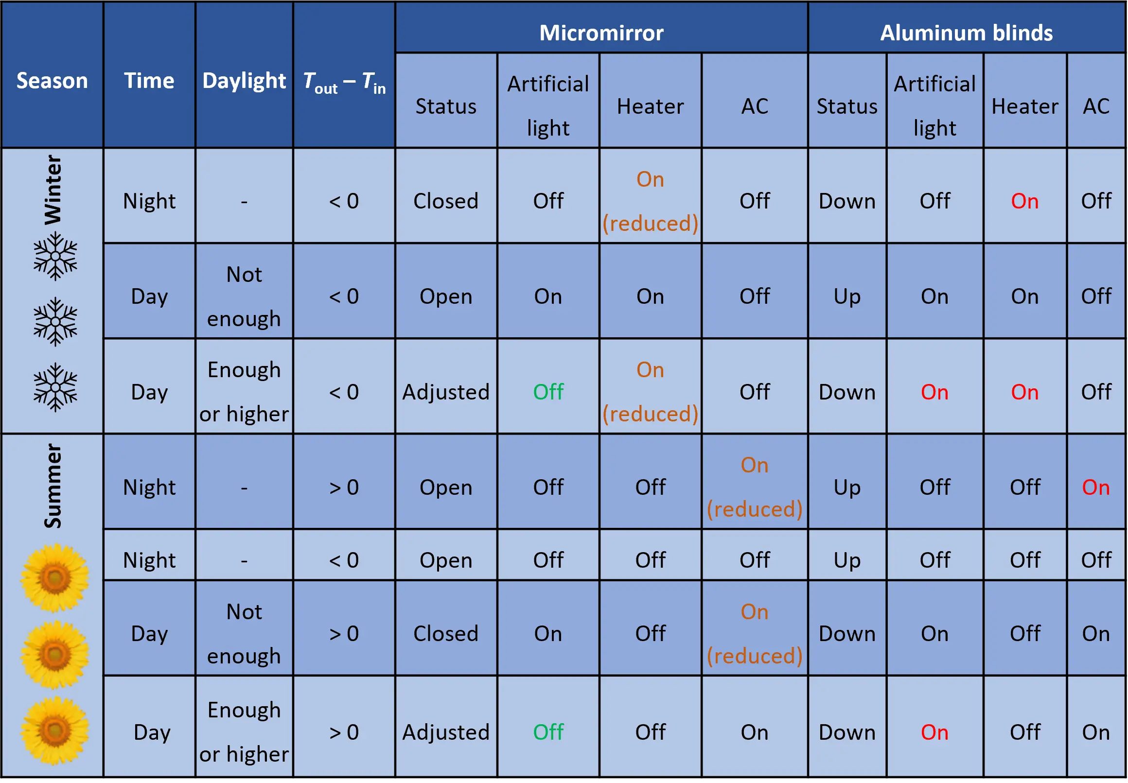
Figure 16. Summary of the situations considered for the calculation of energy savings and amortization time for MEMS smart window and tiltable aluminum blinds equipped window. The temperature difference inside and outside the room is defined by Tout-Tin; outside and inside temperature is denoted by Tout and Tin. MEMS: microelectromechanical systems.
Winter - at night outside working hours: Micromirror arrays are placed in the closed position, and window blinds are down to trap the stored and produced heat inside. Nevertheless, micromirror arrays exhibit a significantly higher efficiency in retaining heat within the room when compared to window blinds.
Winter - during working hours when daylight is less than required: Both the micromirror and window blinds are open and up, respectively, to utilize the maximum available incoming sunlight. However, artificial light is necessarily turned on to maintain the required light inside the room in both cases in order to continue the working environment. The heating load is reduced due to IR absorption since the whole solar radiation is allowed to enter the room.
Winter - during working hours when daylight is equal or higher than required: All the micromirror arrays are open, steering daylight towards the ceiling to use the whole solar radiation and avoid glare effect. The light spot in the ceiling is heating up due to IR radiation, which later works as a radiation heater to reduce the heating load. On the other hand, the aluminum blinds are up when there is enough incoming daylight without a glare effect. However, the aluminum blinds are completely down, blocking the irradiance to avoid glare effect when incoming light is much higher than required. As a result, the room becomes dark, and the heating load increases. Hence, a heater and artificial lighting are required to substitute for the required heating and illumination, respectively.
Summer - at night outside working hours when the temperature inside is higher than outside: Micromirror arrays and aluminum blinds are open and up, respectively, to allow the heat transfer to the outside. Additionally, the energy required to hold the micromirror arrays in a closed state is saved.
Summer - at night outside working hours when the temperature inside is lower than outside: Micromirror arrays and aluminum blinds are closed and down, respectively, to block the heat transfer to the outside.
Summer - during working hours when incoming daylight is less than required: Like in winter, both the micromirror and window blinds are open and up, respectively, to utilize the maximum available incoming solar radiation. However, in both cases, artificial light is turned on to fulfill the required homogeneous illumination inside the room to maintain the working environment. Since the whole radiation is coming inside the room, the cooling load will increase due to IR (NIR, MIR) absorption.
Summer - during working hours when daylight is equal or higher than required: Since micromirror arrays are capable of steering light in selective areas of window, few subfields are open (defined by the number of subfield required to maintain the illumination presented in Table 8 to guide the light towards the ceiling, while the rest of the subfields are closed when the incoming light is much higher than required. This illuminates the room and blocks a bigger fraction of solar heat radiation from coming inside the room simultaneously, thus reducing the cooling load. On the other hand, window blinds are completely down to eliminate uncomfortable glare effect and IR radiation, thus, artificial light is turned on for illumination.
Air conditioners (AC) and heaters are turned on, based on the requirement to maintain an inside temperature of 20 °C for both types of window scenarios in all cases; thus, the input energy of both heater and AC is calculated. Besides incoming heat from solar irradiance, the room occupants, cell phones, computers, table, chairs, cupboards are considered as the sources of heat inside the room. The operating energy for aluminum blinds and micromirror actuation energy is included in the calculation of overall energy consumption for aluminum blinds and micromirror-array-based windows (Table 12).
Table 12. The power consumption to operate aluminum blinds and micromirror-array-based windows.
| Power consumption per m2 | |
| Aluminum blinds | 0.17 W during blind movements |
| Micromirror arrays | 0.0008 W on average for keeping mirror position and mirror movements |
The initial costs are added to the calculated total monthly energy cost for both cases, resulting in the total cost. Consequently, the time taken for the total cost of scenario 1 (aluminum blinds equipped window) to cross the total cost of scenario 2 (micromirror array-based window) is calculated, which is considered as the beginning of the payback period or amortization time for rooms with micromirror arrays-based window, considering different low-e coatings[16].
Based on the assumed room scenario, investment and sun position variation, a simulation tool named “SAVINGS” has been developed to calculate the yearly energy savings and amortization time for micromirror-array-based windows in a best-case scenario. The effect of different low-e coating, and window orientation on the energy savings and amortization time have been simulated and analyzed. The yearly energy consumption of windows equipped with micromirror arrays has been compared to those equipped with conventional aluminum blinds to evaluate the energy savings in heating, lighting, and air-conditioning (AC).
4.1.3 Influence of different low-e coatings
Three different types of low-e coatings (high, moderate and low solar gain) have been considered in this study, and their impact on energy savings is illustrated in Figure 17. The low-e coating does not have a significant effect on yearly light saving since all the low-e coatings have nearly similar transmission in the visible range. However, the low-e coating has a strong influence on yearly AC and heat savings due to the different infrared transmission characteristics.
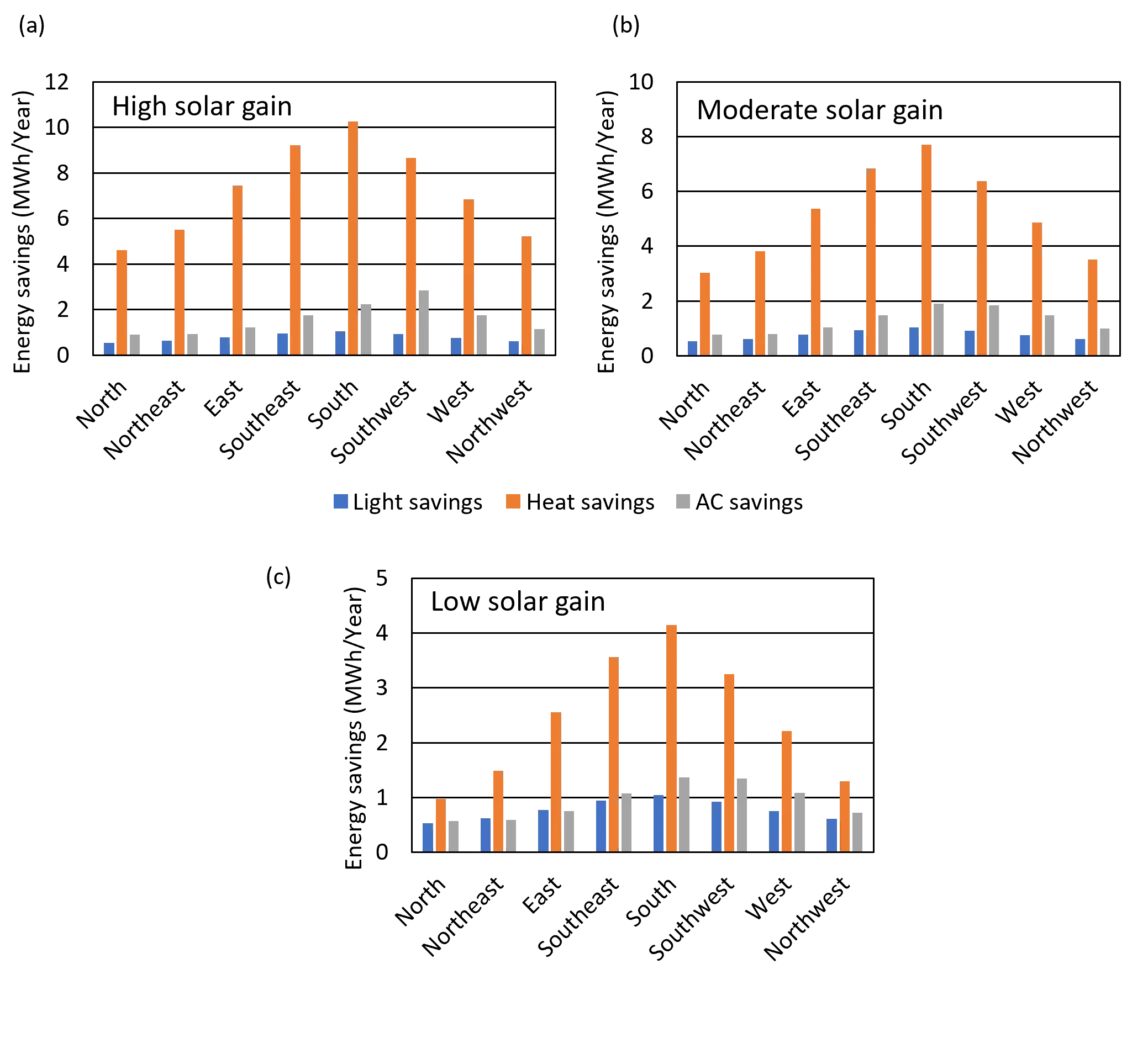
Figure 17. Light, heat and AC savings window with (a) high; (b) Moderate; (c) Low solar gain low-e coating in relation to different window orientations for a model room in Kassel, Germany. Reproduced with permission from[16].
The yearly light, AC and heat savings are around 1 MWh, 2 MWh and 10.5 MWh per year, respectively, for south oriented window with high solar gain low-e coating, 1 MWh, 2 MWh and 8 MWh per year, respectively for moderate solar gain and for low solar gain low-e coating, the resulting savings are 1 MWh, 1 MWh and 4 MWh per year, respectively. The overall yearly savings of south-oriented micromirror array-based windows with high, moderate and low solar gain low-e coating are about 13.5 MWh/year, 11 MWh/year and 7 MWh/year, respectively, which results in an energy savings of 136 kWh, 107 kWh and 66 kWh energy, respectively, for each m2 throughout the year. In comparison to high solar gain low-e coatings, the total yearly energy savings are reduced by about 21% and 50% with moderate and low solar gain low-e coating, it is observed that energy savings and amortization time are strongly dependent on the type of low-e coatings used for the glazing which itself is strongly depending on the location. As a rule of thumb, the low-e coatings should be selected for winter optimization in the European part north of the Alpes and for the summer in the European part south of the Alpes. In addition, the low-e coating should be varied depending on the window orientation. However, the practice is the opposite, as revealed from personal conversations with some window manufacturers.
4.1.4 Influence of window orientation
Maximum solar radiation can be utilized irrespective of the season by a south-oriented window, while the efficient availability of solar radiation gets significantly lower when the window is oriented to north which has strong impact on the energy savings that result in quick or slow return of investment. The light, AC and heat savings are calculated to be 1 MWh, 2 MWh and 10 MWh, respectively, for south-facing windows with high solar gain low-e; however, these values decrease while changing the window orientation towards north to the minimum energy savings value of 0.5 MWh, 1 MWh and 5 MWh, respectively in Figure 17. The total yearly energy savings are highest by the south-oriented windows (13.5 MWh/year); however, these decrease to a minimum while changing the window orientation towards the north (6 MWh/year) with high solar gain low-e. A deviation of approximately 55% is observed when the window orientation changes to north from south. Due to high energy saving capacity of MEMS smart window, the return-of-investment can be achieved in the best-case scenario in 3 years and 7 months for south-facing windows having high solar gain low-e coating, and the slowest in 22 years and 1 months for north-oriented windows with low solar gain low-e. Moreover, a detailed calculation and analysis on the effect of other parameters like Ug and g -value can be found[16].
4.2 Energy saving and amortization time for different locations for different locations
Kassel is not as blessed with many days of sunshine per year as other cities in the southwest of Germany. Therefore, the amortization time simulation is extended using the identical room scenario and calculation methodology for four different cities in Germany, including Kassel, Konstanz, Winterberg and Flensburg (Table 13) using historical data from 2014 to 2019, TRY database created from previous observation and a future predicted TRY database. It is important to note that for a simplified analysis, only low solar gain low-e coating is used for the calculation of amortization time considering different locations since the deviation can be observed clearly.
Table 13. Test locations and corresponding geographic information of four cities in Germany.
| Location | Geographic Coordinate | Elevation [m] |
| Konstanz | N47.673° E9.181° | 409 |
| Winterberg | N51.191° E8.495° | 809 |
| Kassel | N51.313° E9.488° | 178 |
| Flensburg | N54.784° E9.437° | 12 |
The historical (from 2014 to 2019) weather conditions of test locations (four cities) are displayed in Figure 18 where the bar chart represents the average temperature (on left axis) and the line graph describes the average solar radiation (on right axis). It is evident that the temperature and solar radiation levels of each location exhibit significant variations between the seasons of summer and winter, as well as fluctuations every year.
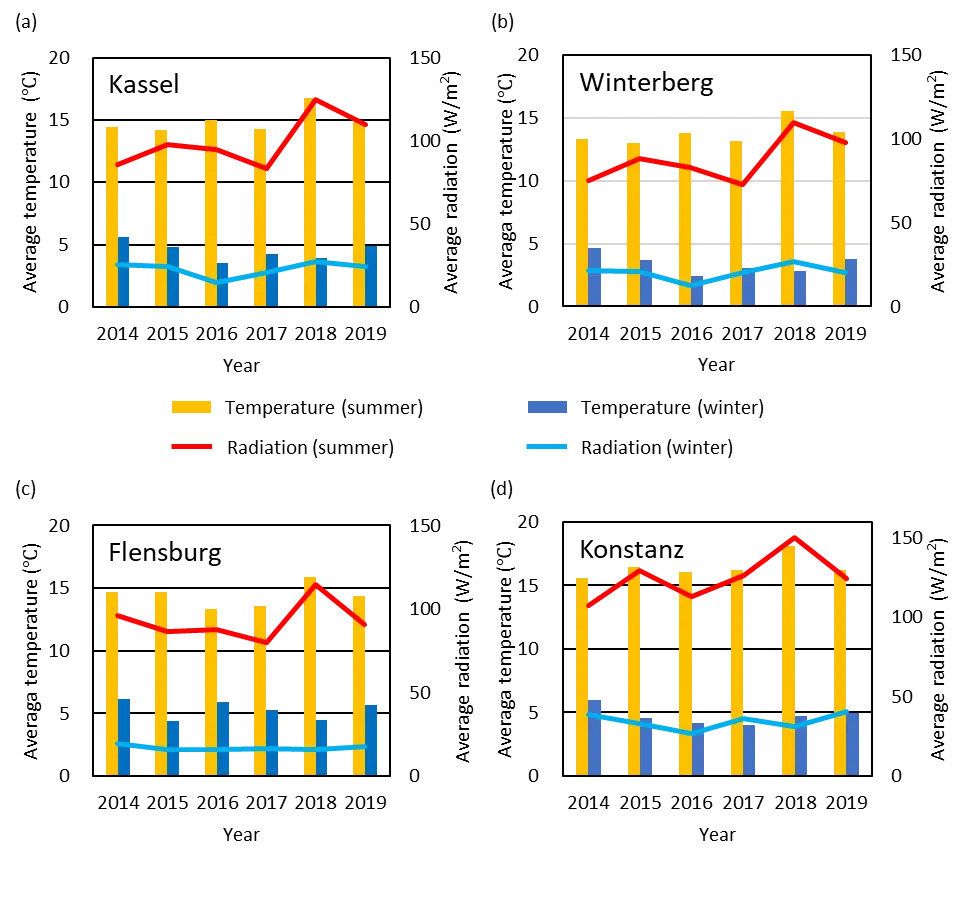
Figure 18. Demonstration of average temperature (in left axis) and solar radiation (in right axis) over the years from 2014 to 2019 for (a) Kassel, (b) Winterberg, (c) Flensburg and (d) Konstanz.
First, two locations of almost identical latitudes can be compared (Kassel and Winterberg). In addition, they are located rather close together, separated in a west-east direction only 60 km, in beeline. So often, a similar weather situation exists in such case. However, cloud accumulation west of Winterberg is observed sometimes at the mainly north-south oriented mountain chain situation. The dominating wind direction is west-east in by far most of the cases. In the case of low wind velocities, the weather in Winterberg and Kassel is often very similar. In the case of very strong west wind sometimes fast changes in cloud coverage scenarios are observed. In those rare days in the years the changes in weather are reaching Winterberg first and on average Kassel about 15-60 min later, depending on wind velocity. In total, this lucky situation allows us to study mainly the dependence of energy savings and amortization times due to drastically (178 m to 809 m) different elevations (178 m to 809 m).
Second, two locations are compared, which are completely different in latitude, elevation and weather. Flensburg is located in the absolute north and Konstanz is in the absolute south of Germany. The beeline distance between both cities is almost 800 km, mainly in a north-south direction. Often, completely different (often opposite) weather is observed between the north and the south. Flensburg shows weather conditions which are more homogeneous over the year, and those of Konstanz are changing much more. Cloud coverage in Flensburg is much higher compared to Konstanz. Flensburg in the north demonstrates lower temperature and less solar radiation.
The historical weather data from 2014 to 2019 used in this work (result shown with black lines in Figure 18) are acquired from the Photovoltaic Geographical Information System of EU science hub, provided by the European Commission[100]. The actual TRY database, which is composed of specific weather periods to match the monthly and seasonal mean values of air temperature and global radiation as closely as possible with the long-term mean values of the base period 1995-2012. They are supposed to simulate weather conditions until 2030 and are collected as above from “Deutscher Wetterdienst” (German Metrological Service) for four German cities/locations[101,102]. The TRY database is generated using long-term measurement and observation series with hourly resolution from various German stations, which are interpolated over the area, taking into account modifications due to urban influences and is based on land use data sets.
In addition to the mean TRY (termed as “normal”), data sets have also been created with a very cold winter half-year (termed as “cold winters”) and a very warm summer half-year (termed as “hot summers”) to consider extreme loads on heating and air conditioning systems. They have been composed of selected real weather situations but originating from different years. These extreme years can be considered as real seasonal periods. Furthermore, TRY databases have been developed based on 24 regional climate models for the period 2031-2060, providing both mean (normal) and extreme values (cold winters and hot summers), identical in structure to the other TRY databases. Two databases are utilized to identify the future TRY—the first database refers to the measurement and observation data from 1995 to 2012 and the second database describes the control period from 1971 to 2000.
The amortization times for the test location are illustrated in Figure 19 where the amortization time is calculated from historical weather data, actual and future predicted TRY with mean (“normal”), extreme winter (“cold winters”) and extreme summers (“hot summers”). For any selected year, the amortization time calculated from historical data lies in the boundary of the amortization time resulted from TRY weather data, however, with an exception in the case of Winterberg in 2018. Therefore, this is an indication that the TRY weather data is applicable for a simplified calculation and an approximate result even for the far future since the amortization time calculations using actual TRY and future predicted TRY cover all results of historical weather data.
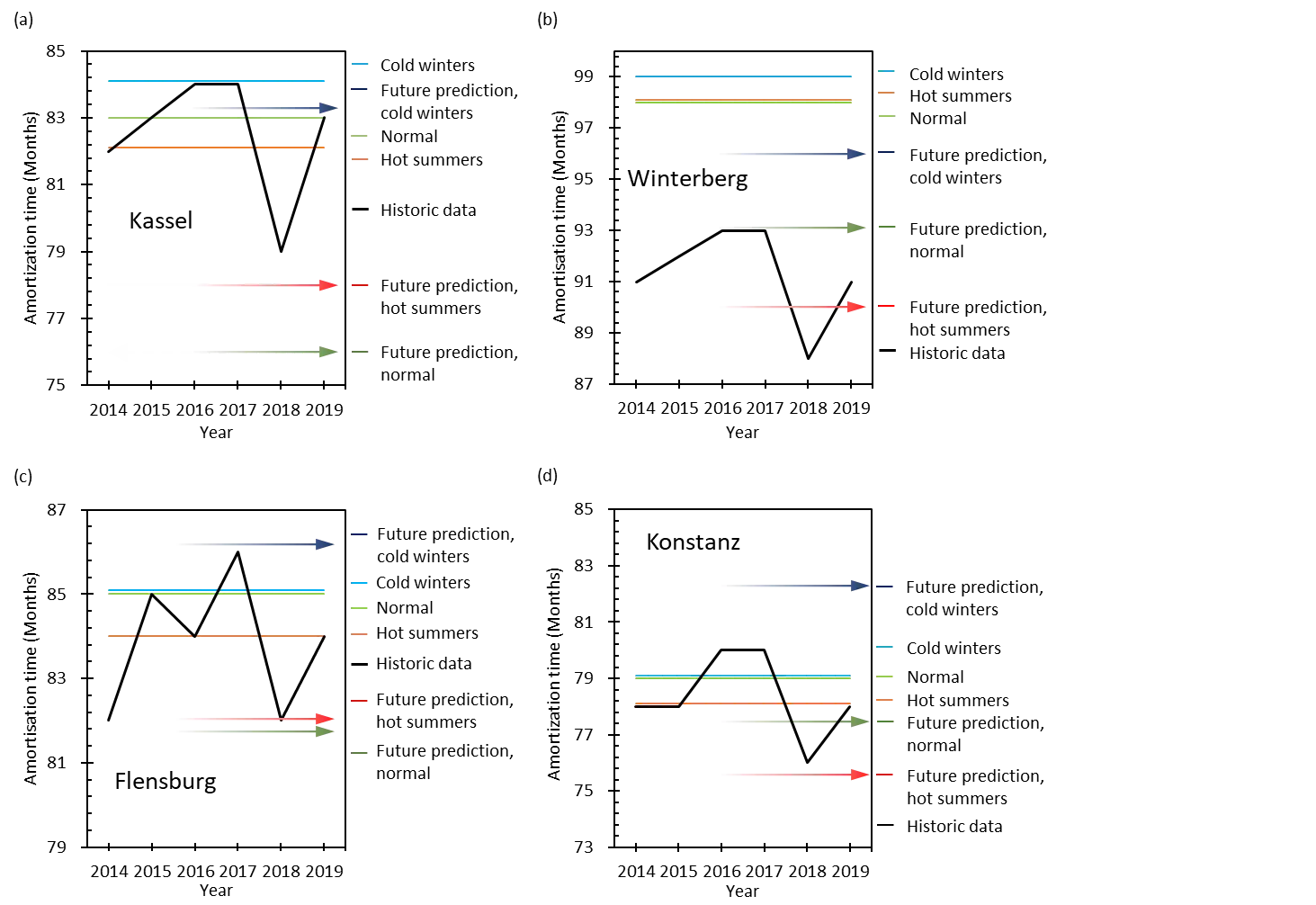
Figure 19. Illustration of amortization time considering the historic data from 2014 to 2019, mean actual TRY generated from previous observation - termed as “normal”, winter and summer dominant actual TRY generated from previous observation - termed as “cold winters” and “hot summers”, and future predicted TRY created by the assumption based on previous observations - termed as “future prediction”, represented by arrows facing right towards the future and for (a) Kassel, (b) Winterberg, (c) Flensburg and (d) Konstanz. TRY: test reference year.
The variations in average temperature and solar radiation have a strong influence on the calculated amortization times. Comparing the results of 2018 and 2019, a reduction of both average temperature and solar radiation leads to a significant increase in amortization time. Multiple comparisons can be performed, and many different conclusions can be drawn on the basis of these data. Two of many possibilities are chosen here.
(i) Kassel and Winterberg nearly have the same latitude and are close to each other, but have very different elevations. Kassel reveals a shorter amortization time mainly due to lower elevation than Winterberg. In 2014 and 2015, for Kassel and Winterberg in Figure 19a,b, show an increase of average radiation at two places and a slight decrease on average temperature. This results in an increase in amortization time for both locations, which indicates the higher influence of average temperature over solar radiation on amortization time.
(ii) Next, Flensburg and Konstanz in Figure 19c,d are compared which are completely different in latitude, elevation and weather. Flensburg and Konstanz reveal a north-south beeline separation of almost 800 km, with often opposite weather being observed. Flensburg depicts more homogeneous weather over the year, and the weather in Konstanz is changing more often and sometimes quickly. In addition, the cloud coverage in Flensburg is much higher than in Konstanz. Flensburg in the north demonstrates lower temperature and less solar radiation. As a result, with all parameters being very different between Flensburg and Konstanz, the amortization time in Konstanz is found to be much shorter.
4.3 Energy saving and amortization time calculation for Qingdao*, China and Riyadh*, Saudi Arabia
If appropriate databases similar to the TRY data from German Metrological Service would exist for major cities all over the year, this novel simulation tool would enable an estimate for the amortization times and energy savings for these locations. Normally, many parameters change at the same time when comparing different cities. In experiments and simulations this is always a non-optimum situation trying to identify from which “changed parameter” the dominating impact arises. Being able to generate artificial cities (we called them CityName*), the reduction of parameters changed at the same time is reduced, allowing for more precise results of the comparisons and more reliable conclusions. Nevertheless, statements and results from simulations based on statistical data (even if directly measured with a lot of effort) remain quantitatively a bit uncertain but enable us to identify trends and qualitative take-home messages.
In order to compare and analyze the energy saving and amortization time calculation from a more global perspective, two cities outside of Germany (Qingdao*, China and Riyadh*, Saudi Arabia) are considered in the calculation using historical data from 2014 to 2019, as shown in Figure 20.
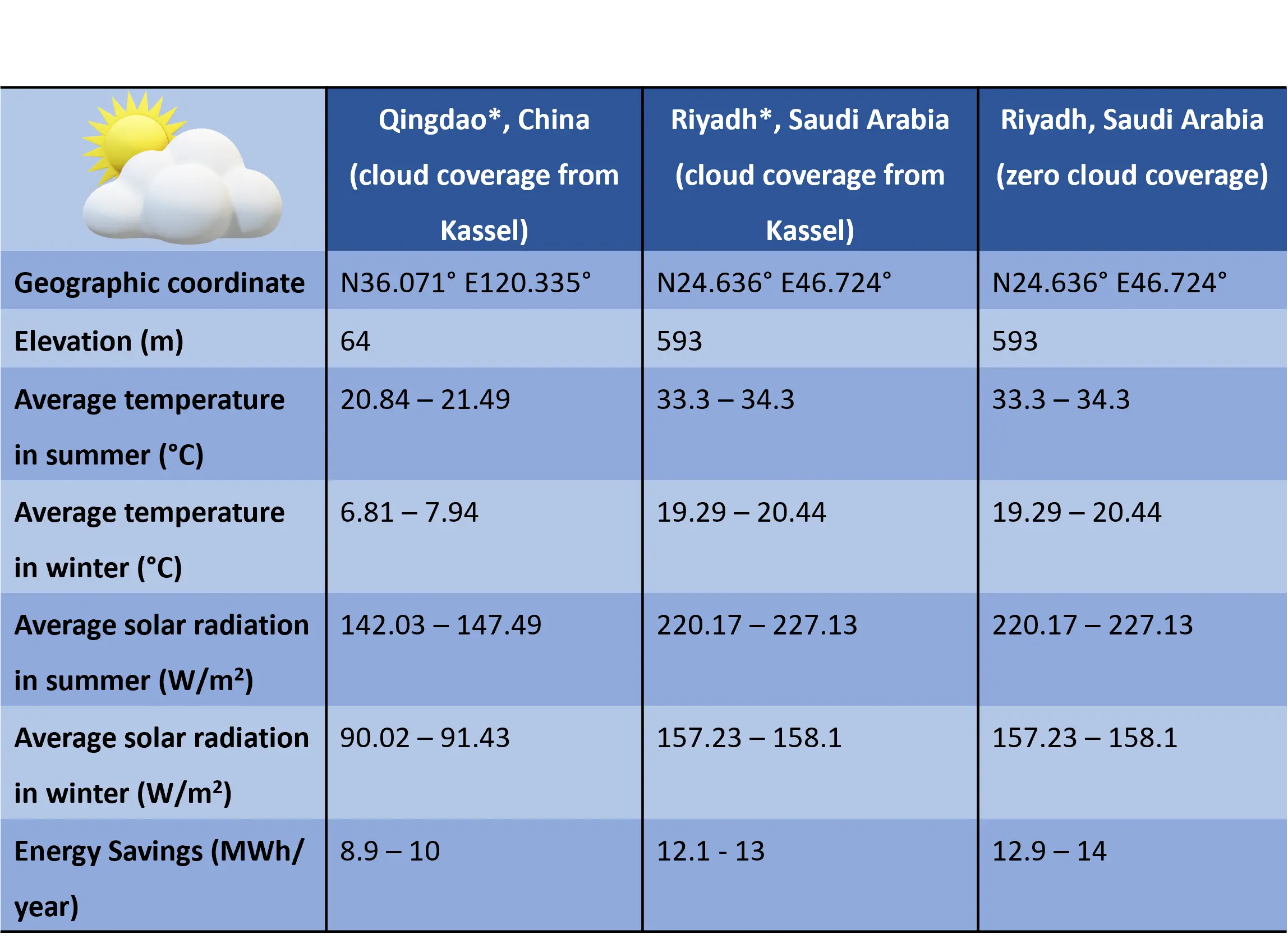
Figure 20. Geographic information, a summary of historical weather data and calculated amortization time for Qingdao, China and Riyadh, Saudi Arabia.
Note that it was impossible to obtain datasets which are comparable in level of detail to the above used TRY sets. Therefore, this gave us the possibility to compare the influence of latitude and different irradiation and temperature. Intentionally, we maintained the cloud coverage of Kassel also for Qingdao* and Riyadh*. This enables us to study the influence of the above-mentioned factors independent of cloud coverage, an interesting scenario.
• Comparing Kassel and “Qingdao*” we obtain shorter amortization times for “Qingdao*”. Since the weather condition in Kassel and Qingdao are quite identical, this assumption is adequate.
• Comparing Kassel and “Riyadh*” we obtain shorter amortization times for “Riyadh*”. In that case, the real cloud coverage in Riyadh is very much less and mainly zero.
• Now Qingdao* and Riyadh* are compared directly, assuming an identical cloud coverage. It is observed that the location with a lower latitude (Riyadh*) shows a significant higher energy saving of 12.1-13 MWh/year (shorter amortization time of 62-63 months) compared to 8.9-10 MWh/year (amortization time of 75-77 months) for Qingdao*.
• Moreover, the energy saving increased to 12.9-14 MWh/year (amortization time is reduced to 56-57 months) for Riyadh in a further calculation using zero cloud coverage since it has much less cloud coverage due to its location in the desert. The higher energy saving and shorter amortization time also results from higher average annual temperature and higher solar radiation. From the comparison of all four cities in Germany and the two selected global cities, it is evident that the temperature and the solar radiation have different weights in influencing the energy saving and amortization time while considering them individually.
4.4 Overview of energy saving simulation based on different window smart technologies
Numerous energy simulation studies have been published concerning the energy saving potential of different smart windows considering the influence of location, window-to-wall ratio, window orientation, climate condition, type of building and building size. McNeil et al.[103] has conducted a parametric study that annual lighting energy use can be reduced by 22-27% using Optical Light Shelf (OLS) compared with unshaded windows with standard Venetian blinds. Zhou et al.[104] simulated that the annual HVAC (heating, ventilation and air conditioning) energy consumption by 19.1%, 24.3%, 25.4% and 44.6% for Shanghai, Las Vegas, Riyadh and Singapore, respectively while using 1 cm hydrogel-laminated thermos responsive smart window can be reduced in comparison to ordinary glass windows. A significant reduction in annual energy consumption is reported for cities near the Tropic of Cancer (Athens, Guangzhou and Miami) using W-VO2-based smart window[105]. An energy saving up to 324.6 MJ·m-2 using passive radiative cooling-regulating thermochromic (RCRT) windows is reported by Wang et al.[106]. Hoffman et al.[107] has reported that the thermochromic windows can reduce 13.7-16.7% energy use with south, east, and west orientation, in hot climates. It is reported by Wang et al.[108] that the energy saving rate of Electrochromic windows compared to low-e window is approximately 22%. Detsi et al.[15] calculated a reduction of annual primary energy use by 18.5% and 8.1% for Athens and Stockholm, respectively by combining electrochromic and thermochromic layers on the outer pane of the triple insulation glazing unit. Nageib et al.[14] has reported the effect of window orientation (west, east, south and north) and Window-to-Floor-Ratio (WFR) on energy saving using different smart windows in an office building in upper Egypt. A cooling energy saving of 35%, 30%, 24% and 27% is calculated for electrochromic, gasochromic, thermochromic and SPD windows in comparison to the normal window glazing for 32% WFRs. Lighting energy saving possibility of 39-43% is simulated by McNeil et al. in the best case for a 12 m2 office space using a 3M prismatic film[81]. Alghamdi et al. reported an energy saving of 4.2 W/day using PDLC glass[109]. Depending on various factor mentioned earlier, energy saving of 0.39-2.11 KWh/ft2 is reported for Daylight redirecting film (DRF) in windows[110]. A reduction in cooling, heating and fan requirements by 6.5%, 1.5% and 5.7% is simulated by Vlachokostas et al.[111] for Liquid Filled Prismatic Louver in window in comparison to baseline glazing.
5. Power consumption in switching and holding status
The power consumption is reported to be independent of temperature[112] for SPD smart glass and decreases with rising temperature[113,114] for PDLC. For MEMS smart glass, the power consumption in the holding status is strongly determined by the leakage current through the SiO2 insulation layer. Leakage current measurements were conducted for a 0.0025 m2 sample in a temperature cycle of 0-40 °C, in which the measured value at different temperatures in Table 14 exhibit an increasing trend of leakage current with increasing temperature. This also implies that the power consumption for MEMS smart glass increases with increasing temperature.
Table 14. measured leakage currents at different temperature through SiO2 insulation layers of different thickness at four different temperatures.
| MEMS smart glassof 5 × 5 cm2 area | Leakage current [nA]measured at 50 V | |||
| Thickness SiO2 = 1,000 nm | 1.87 | 7.72 | 21.8 | 73.7 |
| Thickness SiO2 = 1,200 nm | 0.085 | 0.604 | 1.38 | 4.76 |
| Temperature | 0 °C | 15 °C | 25 °C | 40 °C |
This is due to the temperature dependences of (i) different bulk conduction mechanisms in insulating materials such as Poole-Frenkel, trap-assisted tunnelling, hopping conduction, space-charge-limited conduction, and impurity conduction as well as the influence of (ii) electrode-limited conduction such as Schottky emission, Fowler-Nordheim tunnelling, direct tunnelling and thermionic field emission. For 20 °C and 40 V applied voltage, a power draw of 0.018 mW/m2 is resulting for 1.2 µm SiO2 and of 0.3 mW/m2 for 1 µm SiO2. This also corresponds for the holding status.
In Figure 5, the energy consumption of a specific actuation/switching scenario is compared. We took into account the scenario identified by the company Warema for the average daily use with conventional window blinds: 2 complete open-close-open cycles and 10 adjustments. In this case, a comparison could be performed between blinds (external and internal) and smart glass based on electrochromic, PDLC, SPD and MEMS technology. The energy consumption for this case is given in Figure 5. The power consumption during switching is much easier to quantify than the holding.
We have evaluated 60 different references from the scientific literatures as well as company homepages.
• For electrochromic smart glass the holding power consumption ranges between 0 W/m2[115-117], 0.01 W/m2[118], 0.1 W/m2[119], 0.4 W/m2[116], and 1 W/m2[120]. The switching power ranges between 0.05 W/m2 and 3 W/m2[115-122]. Thus, it is very low or even zero in the holding mode and at about 1 W/m2 in the switching mode.
• For PDLC smart glass, the holding power consumption ranges between 1.5 W/m2[123], 2 W/m2[124], 3 W/m2[125], 4 W/m2[123,126], 5 W/m2[127,128], < 5 W/m2[129], < 5.4 W/m2[130], 5.5 W/m2[131], 7 W/m2[128,132], < 10 W/m2[133], 10 W/m2[134], 13 W/m2[135]. The switching power ranges between 2 W/m2[136] and 5 W/m2[131,135-137]. In holding mode the power consumption is at about 5 W/m2 in average and in switching mode also at about 5 W/m2 in average. Thus, PDLC smart glass generally has higher power consumption as electrochromic smart glass.
• For SPD smart glass, the holding power consumption ranges between 0.075 W/m2[138], 0.65 W/m2[139], 1.2 W/m2[140,141], 1.5 W/m2[142], and 12 W/m2[143]. The switching power ranges between 0.1W/m2 and 5 W/m2 and even much higher[138,140,141]. Here, a wide spread of published values were found.
• For MEMS micromirror smart glass, the power consumption in holding mode depends also on the angle of light steering, due to different required current actuation voltages. No power is consumed in completely open state. The opposite holds, if the windows have to be completely closed at night to guarantee privacy or to avoid heat loss in winter. A power consumption of about 0.3 mW/m2 occurs for 50 V in winter. In summer, the completely closed window approximately require 1.5 mW/m2 to avoid temperature increase inside the room. Holding modes between these extreme values are between 0 and 1.5 mW/m2. An average value for all over the year is assessed at 0.8 mW/m2.
In summary, a comparison of the power consumption between different smart glass is very difficult. For the holding mode, the power consumptions are lowest for electrochromic and MEMS, medium for SPD, and highest for PDLC. For the switching mode, the power consumptions are far lowest for MEMS, low for electrochromic, medium for SPD and highest for PDLC.
6. Reliability Studies Via Different Rapid Aging Tests
Technical systems are exposed to harsh environmental situations such as temperature changes; ultraviolet (UV), visible, or infrared (IR) radiation; mechanical vibrations and shocks; as well as weather conditions such as humidity, rain, ice, snow, wind, and sandstorm. Therefore, quality control plays a crucial role in research and industrial production to experimentally simulate long-term reliability issues concerning all these points. Such rapid aging tests are performed to gain as much information as possible about failure. This enables us to estimate mean-time-to-failure rates, lifetimes, and reliability data. Aging tests reveal a failure probability as a function of time (in units of several years) the so-called Weibull or bathtub curve[144] - which is characterized by a time interval at the beginning showing a decreasing failure rate, followed by a long time-interval characterized by an almost constant failure rate, and a time interval of re-increasing failure rates at the end. For example, burn-in processes are performed for many semiconductor devices, e.g. for semiconductor lasers, to directly reach the long second interval of low failure rates.
Our micromirror arrays for active light steering in smart windows are sealed and protected in a noble gas atmosphere inside the insulation glazing (at least double glazing), as depicted in Figure 1, Figure 2 and Figure 9. The insulation glazing is filled with noble gas (argon or krypton), since single-atomic gases exhibit the best thermal insulation properties next to vacuum. Such arrangement benefits the micromirror arrays enormously due to the absence of moisture and oxygen that could harm the metallic surfaces of the mirrors in the long term. Therefore, the remaining reliability issues which could cause material and structural failure are narrowed to mechanical shocks, vibrations, multiple movements, extreme temperatures, sudden temperature variations, and UV radiation. Extensive experiments on all these issues are ongoing and have already shown very promising preliminary results. Here we report on the data, which have been achieved at the moment of manuscript submission.
In almost all cases MEMS micromirror arrays in double insulation glazing are used for tests. Only the 1D vibration test is performed with just MEMS arrays on (10 × 10) cm2 glass substrates (not mounted in modules), since weight reduction was necessary to reach the high vibration frequencies (> 3 kHz).
6.1 Vibration tests in 1D and 2D
Potentially, MEMS micromirror smart glass is future applications could be exposed to the following mechanical vibration and shock scenario:
• During delivery/transportation by trucks, vibrations, accelerations, and retardations are present (60-1,000 Hz, and a maximum acceleration of 6.9 g for 60-150 Hz and of 13.8 g for 150-1,000 Hz; g = gravitational acceleration constant of the Earth). These are typical test parameters for fragile elements such as filaments of truck lamps[145].
• Unloading of the window modules from the truck, in the worst case with extensive lowering and dropping movement.
• Forceful closing movement of the window, for instance from strong gusts of wind.
• Installation and mounting of window modules, for example with repeated hitting and fitting movements using a rubber mallet.
• Wind-stimulated oscillations of buildings (low frequency range velocities up to 1 mm/s).
• Tension attacks by wind squalls on the pane.
• Volley attacks on the pane in stormy weather.
• Accelerations and retardations during opening and closing of the window.
• Seismic earth vibrations (0.5-10 Hz)[146].
• Vibrations of windows caused by urban or air traffic (typically 5-100 Hz)[146].
• Floor and wall vibrations in buildings, potentially from internal sound sources in close range of the building resonances (2-15 Hz)[146].
• Frequency peaks from internal motors or pumps (e.g. 50 Hz and multiples of it).
To experimentally simulate rapid aging due to fast movements, one- and two-dimensional (1D, 2D) mechanical vibration tests have been performed. The 1D vibrations are oriented vertical to the substrate plane. The 2D actuations are performed in a plane including the directions vertical to the substrate and perpendicular to the hinge axis (i.e. inside the substrate plane).
For the 2D vibration, two electromotors with unbalanced axis were used. The micromirror samples were placed in horizontal position and undergo forced oscillations under sinusoidal lateral external mechanical excitation up to frequencies of 100 Hz. The two masses used for the unbalanced rotation can be adjusted at variable phase shifts (0-2π) between the two masses. A phase shift of π/2 enables maximum tilt vibration, a phase shift of π reveals nothing of interest, and a phase shift of 2π or 0 results in maximum acceleration values. Values in between these situations provide adjustable transition states between the two bordering cases of maximum tilt and maximum acceleration. Several samples have been tested under a long-term vibration at a frequency of 60 Hz and maximum acceleration conditions (phase shift of 2π for the two masses). The vibration tests at 60 Hz have been performed to represent building vibrations caused by compressors and pumps, for example. Using an optical macroscope with resolution of 8 µm, images have been recorded in intervals of several days to document any visible changes on the samples. Care has been taken to ensure that always the identical sample positions are inspected.
The influence of gravity and inertia forces is minimized in the micro world, thus nearly eliminating material fatigue. This is treated in detail in our previous papers[147]. As a conclusion, with shrinking mirror sizes (down-scaling), the relative importance of electrostatic forces used for the actuation grows on the expense of the strongly vanishing gravity and inertia forces responsible for material fatigue. The tests results conclude that no failure of MEMS micromirror smart glass is expected during the transportation and installation process, as well as in long-term use.
The second setup for long-term vertical 1D vibration enables a frequency variation in the range of 0-6 kHz. The sample holder is fixed to a membrane equipped with a thin permanent magnetic plate at the bottom. The alternating magnetic field of the coil below excites the membrane to forced oscillations at variable frequencies. The oscillation frequency is generated by a sine generator which after amplification feeds the coil.
The 1D actuation setup can reach frequencies up to 6 kHz, but at small amplitudes. In contrast, the 2D actuation setup enables very large amplitudes but only for frequencies up to 100 Hz. Bot setups are complementary to each other. The results of the 1D and 2D vibration tests are summarized in Figure 21. All samples survived without any damages and physical changes.
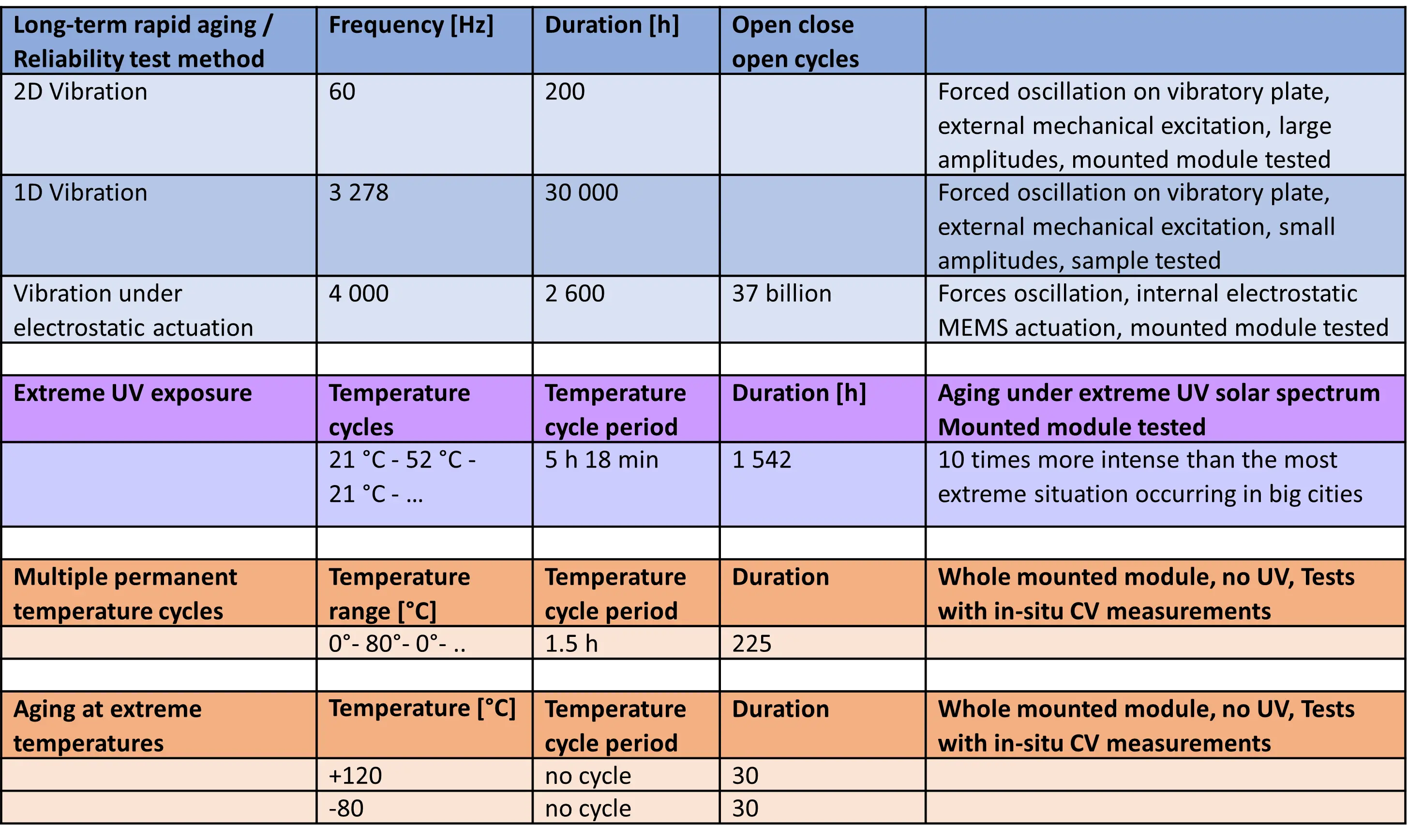
Figure 21. Overview on different reliability studies and rapid aging tests performed for MEMS micromirror arrays. MEMS: microelectromechanical systems.
6.2 Long-term electrostatic actuation
Fatigue tests of the micromirrors have also been performed with electrostatic actuation of different frequencies for a long period of time. The set-up allows excitations in the frequency band 0-10 kHz. By placing a light source on one side of the sample, the light transmitted through the micromirror arrays is detected by a fast photodiode on the opposite side and displayed as a transient intensity by means of an oscilloscope. Since the transmitted light intensity is related to the deflection angle of the micromirrors by geometrical means, the actuation characteristics of micromirror with increasing frequencies can be examined through observation of the transmitted intensity, which is defined by the deflection angle. Considering the typical average changes of the micromirrors in smart windows initiated by the user, the performed > 1010 cycles of opening and closing movements would correspond in a simplified approximation to extrapolated lifetimes of at least 40 years. This are important and encouraging results, demonstrating the sustainability and robustness of microsystem technology, under the assumption that the elements are sufficiently miniaturized. The results of the long-term electrostatic actuation tests are summarized in Figure 21.
6.3 Performance under strong UV irradiation
On earth, some cities have highest UV indices: Singapore (13 in March), Bangkok (12 in March, April, July, and August), Tokio (10 in July), Los Angeles (10 in July), Sydney (10 in December), Berlin (7 in June and July), Buenos Aires (10 in December). Also considering the angle of sun light incidence on a vertically oriented window, these extremely high values are relativizing (note that the sun is standing nearly vertical in Singapore). In our experiments, solar irradiance in the UV is spectrally emulated by UV LED arrays using a selection of different wavelengths. The spectral irradiance of the LEDs is chosen to be approximatively ten times higher than the most extreme situations occurring in big cities.
Since UV LEDs have an approximative efficiencies of 0.1% at 230 nm, 1% at 250 nm and 2% at 350 nm, they are very efficient heat sources rather than light sources. The heat is used to perform temperature cycles at the same time. To save the lifetime of the LEDs the temperature did not exceed 52 °C. To avoid waste of energy (i) no cooling ventilation system has been installed for the LEDs, (the generated LED heat is used completely to temper the chamber), (ii) the whole chamber has been insulated by Styrofoam and (iii) the inside walls of the chamber have been coated by ultra-high reflective UV foils, to make full use of the UV light. One temporal cycle includes the radiation phase (also heating phase) of 1 h 20 min and the dark phase (also cooling phase) of almost 4 h. Thus, a total cycle is 5 h 18 min, during which the temperature rises from 21 °C to 52 °C. To check whether the MEMS array is still functioning properly under the test, CV measurements have been performed in-situ and in breaks where the temperature was cooled down to room temperature. No failure has been observed. The results of the UV measurements are summarized in Figure 21.
6.4 Performance at extreme temperatures and after multiple temperature cycles
The temperature cycles have been performed to simulate varying temperatures (i) in winter and summer, (ii) in day and night times as well as (iii) during weather changes. Multiple cycles between 0 °C and 80 °C have been performed. Each cycle consists of 20 min heating period, 20 min holding at 80 °C (CV measurements were done), 20 min active cooling period, 30 min holding at 0 °C (CV measurements were done). The CV measurements were performed to check if the MEMS smart glass module is still functioning properly under the test.
The micromirror arrays also show full operability at extreme temperatures of -80 °C and 120 °C. Lower and higher temperatures than this range could not be measured up to now, due to limitation of our climate chamber where more extreme temperatures are not feasible. However, such studies already demonstrate a large operating temperature range fully sufficient for building applications. The results are summarized in Figure 21. The studies demonstrate weather-, daytime- and season-independency of the performance of our MEMS smart glass.
In summary, these following rapid aging tests have been performed on our MEMS smart glass: long-term actuation at 4 kHz (mechanical resonance frequency is 7 kHz) over 260 billion cycles, operation at extreme temperatures down to -80 °C and up to 120 °C, multiple extreme temperature cycles, UV aging at variable temperatures, shock tests and mechanical vibration treatment over 31,000 h. Surviving different tests show a long and stable maintenance free lifespan.
7. Conclusion
An overview is given on smart glass in general, followed by particular focus on MEMS smart glass. Our MEMS micromirror smart window technology shows multiple advantages such as much larger operating temperature ranges, benefits for all seasons, perfect color neutrality, safety in case of sudden power loss, longer lifetimes, higher reliability, resistance against UV radiation and much higher potential of energy saving and reduction of CO2 emission. A switching time of 1 µs for a total closing is reported for MEMS smart glass, which is significantly faster than the times reported for all other technologies. A modulation contrast of 7,700 for the light intensity is reported for MEMS smart glass, which is substantially wider than the modulation contrast reported for all other smart glass technologies. Considering an identical operation scenario (two complete open/close/open cycles and ten adjustments), the MEMS smart glass reveals much lower energy consumption in comparison with all other systems. In contrast to thermochromic, chemochromic, and electrochromic systems, which are based on absorption, heating of the window is negligible for MEMS smart glass. Nevertheless, a clear view through the window is better for electrochromic smart glass than for all other technologies.
Furthermore, simulations of active daylight steering by improved ray tracing simulations are reported. The light distribution and guiding via quadruple glazing equipped with MEMS smart glass inside a model room have been studied. Different user positions inside the model were considered and light distributions on ceiling, walls, floor and a working plane 85 cm above the floor are simulated and displayed. Next, the benefit of the MEMS smart glass is demonstrated by comparing facades with and without MEMS micromirrors. Different micromirror angular tilts inside the cooperating subfields are identified to generate a spot moving with the user’s position inside the room. Huge improvements in illumination distributions can be demonstrated by this MEMS smart glass application. This considerably improves heat management in buildings in winter and summer and saves huge amounts of energy for heating, climatization and artificial lighting. In addition, it enables novel personalized lighting and provides valuable contributions to human health and well-being, productivity, and safety. Sustainable and energy-efficient active window designs are crucial to making the most of the available natural solar resources—our MEMS smart glass could make an important and very large contribution to save global energy and reduce global CO2 emission.
Finally, the yearly energy savings and amortization times of investments have been simulated for MEMS smart glazing in direct comparison to windows with conventional automated external blind systems for planned office rooms with specific user actions over the year. For our simulations, actual and future predicting databases using real weather data over five, ten or twenty years are used for different locations in Germany: Kassel, Konstanz, Winterberg, and Flensburg, revealing different latitudes, elevation, and weather conditions. The weather data were recorded in minute span and averaged to generate each hour’s characteristic values, revealing real weather data including temperature, cloud coverage, sun irradiance and others. Season and daytime dependent sun positions, cloud coverage degree; room scenarios; investment in lighting, heating, and air conditioning; different window orientations, energy cost; and different low-e coatings were considered in the simulation. Varying the input parameters, several scenarios are simulated, presented and compared.
In addition, a comparison of Kassel with Qingdao* and Kassel with Riyadh* based on historical weather data is performed. Best case simulations of amortization times of the investment in smart glass reveal less than 5 years for south-oriented windows in Riyadh, Saudi Arabia while considering no cloud coverage. Our simulation program can be used for all cities in the world (northern or southern hemisphere) for which a reliable weather database is available. Databases from different cities can easily be loaded into our simulation program, and the simulation parameters can be individually chosen, such as low-e coating type; window orientation; floor level; investment in lighting, air conditioning and heating; reduction degree of engine power reduction; as well as MEMS smart glazing sales price and energy cost. Note again that MEMS smart glass can be supplied according to customer requirements in different categories from standard to premium and in different price ranges. This is the average price ranging from standard to premium embodiment of the window. The advantage of this simulation tool is that by having detailed weather for a specific location as a precondition, the energy savings and amortization times of MEMS smart glass can be calculated for arbitrary locations on Earth.
Deviations from these simulation results considering a best-case scenario will occur from different user behavior, possible parameter changes by the users in the control system, different weather data, varying energy and raw material prices, new building regulations, and most importantly weather situations. Notwithstanding, these simulations provide an estimate of the potential of MEMS smart glass for buildings.
A comparison of the power consumption between different smart glass is very difficult. For the holding mode the power consumptions are lowest for electrochromic and MEMS, medium for SPD and highest for PDLC. For the switching mode, the power consumptions is far lowest for MEMS, low for electrochromic, medium for SPD and highest for PDLC. MEMS micromirror glazing for heat management and light steering in buildings can save up to 35% of energy and CO2 emissions. Considering the data simulated in this publication, they could significantly contribute to slowing down global warming if applied worldwide. Energy saving is a very important point, but other very beneficial aspects come on top, such as valuable contributions to human health, well-being, productivity, and safety.
Acknowledgements
The author would like to thank Smolarczyk M, Lyu Z, Ittehad A, Buchschacher P, Anklin J, Caruso G, Nandakumar A, Muringakodan S,Yang XH, Albdour R, Abbarla N, Schmid J, Krumpholz J, Friedrichsen A, Nazemroaya S, Al-Qargholi B, Wilke H, Luo H, Hillmer V, Tatzel A, Viereck V, Jäkel A, Worrapattrakul N, and Waitz FV for the fruitful discussions and technological support; Energy Glas GmbH in Wolfhagen for the technical assistance in housing of insulation glazing; Technoform GmbH in Kassel for providing spacer material for the housing; as well as German Federal Ministry of Education and Research funding program Photonics Research Germany for financial support.
Authors contribution
All authors contributed equally to this work.
Conflicts of interest
The authors declare that there are no conflicts of interest.
Ethical approval
Not applicable.
Consent to participate
Not applicable.
Consent for publication
Not applicable.
Availability of data and materials
Not applicable.
Funding
This research was financed by the German Federal Ministry of Education and Research funding program Photonics Research Germany (contract no. 13N14517 and 13N15740, 13N15741), DBU (grant agreements AZ23717, AZ20012/189 and AZ3550133), and EU MEM-4WIN, EU NEXT BUILDINGS (grant agreements 314578 and 284533).
Copyright
© The Author(s) 2023.
References
-
1. Core Writing Team, Lee H, Romero J. Climate Change 2023: Synthesis Report. Contribution of Working Groups I, II and III to the Sixth Assessement Report of the Intergovernmental Panel on Climate Change. Geneva: IPCC. 2023.[DOI]
-
2. Rahman MM. Do population density, economic growth, energy use and exports adversely affect environmental quality in Asian populous countries? Renewable Sustainable Energy Rev. 2017;77:506-514.[DOI]
-
3. Alam MdM, Murad Md W, Noman AHMd, Ozturk I. Relationships among carbon emissions, economic growth, energy consumption and population growth: Testing Environmental Kuznets Curve hypothesis for Brazil, China, India and Indonesia. Ecol Indic. 2016;70:466-479.[DOI]
-
4. Ohlan R. The impact of population density, energy consumption, economic growth and trade openness on CO2 emissions in India. Nat Hazards. 2015;79(2):1409-1428.[DOI]
-
5. Gupta J. A history of international climate change policy. WIREs Clim Change. 2010;1(5):636-653.[DOI]
-
6. United Nations Framework Convention on Climate Change (UNFCCC) [Internet]. The Paris Agreement; c2016 [cited 2023 Sep 10]. Available from: https://unfccc.int/sites/default/files/resource/parisagreement_publication.pdf?download.
-
7. Jacobson MZ, Delucchi MA. Providing all global energy with wind, water, and solar power, Part I: Technologies, energy resources, quantities and areas of infrastructure, and materials. Energy Policy. 2011;39(3):1154-1169.[DOI]
-
8. Ruggeri AG, Gabrielli L, Scarpa M. Energy Retrofit in European Building Portfolios: A Review of Five Key Aspects. Sustainability. 2020;12(18):7465.[DOI]
-
9. Balaras CA, Droutsa K, Dascalaki E, Kontoyiannidis S. Deterioration of European apartment buildings. Energy Build. 2005;37(5):515-527.[DOI]
-
10. Sandberg NH, Sartori I, Heidrich O, Dawson R, Dascalaki E, Dimitriou S, et al. Dynamic building stock modelling: Application to 11 European countries to support the energy efficiency and retrofit ambitions of the EU. Energy Build. 2016;132:26-38.[DOI]
-
11. Bundesministerium für Umwelt, Naturschutz und nukleare Sicherheit [Internet]. Treibhausgasemissionen sinken 2020 um 8,7 Prozent; c2021 [cited 2023 Sep 23]. German. Available from: https://www.bmuv.de/PM9484
-
12. Gramm S. Energieeffiziente Beleuchtung unter Berücksichtigung von Tageslicht und verschiedenen Nutzeranforderungen [dissertation]. Berlin: Technische Universität Berlin; 2015. Available from: https://depositonce.tu-berlin.de/bitstreams/35cf4916-a314-45bc-a300-ef5aacc14224/download
-
13. Birchall S, Gustafsson M, Wallis I, Dipasquale C, Bellini A, Fedrizzi R. Survey on the energy needs and architectural features of the EU building stock [Preprint]. 2016. Available from: http://www.diva-portal.org/smash/get/diva2:949958/FULLTEXT01.pdf
-
14. Nageib AM, El-Zafarany AM, Mohamed FO, El-Hefnawy MH. Effect of smart glazing window on energy consumption inside office building. Mater Sci Forum. 2020;1008:72-83.[DOI]
-
15. Detsi M, Manolitsis A, Atsonios I, Mandilaras I, Founti M. Energy Savings in an Office Building with High WWR Using Glazing Systems Combining Thermochromic and Electrochromic Layers. Energies. 2020;13(11):3020.[DOI]
-
16. Hasan MK, Baby S, Muringakodan S, Nandakumar A, Iskhandar MSQ, Hillmer V, et al. Energy Saving and Amortization Time Simulation for a Model Room with MEMS (micro electromechanical system) Smart Glazing. 77th ed. In: Sörgel T, editor. Jahrbuch Oberflächentechnik. Bad Saulgau: Leuze Publishing House; 2021. p. 163-188.[DOI]
-
17. Brzezicki M. A systematic review of the most recent concepts in smart windows technologies with a focus on electrochromics. Sustainability. 2021;13(17):9604.[DOI]
-
18. Akram MW, Hasannuzaman M, Cuce E, Cuce PM. Global technological advancement and challenges of glazed window, facade system and vertical greenery-based energy savings in buildings: A comprehensive review. Energy Built Environ. 2023;4(2):206-226.[DOI]
-
19. Hillmer H, Al-Qargholi B, Khan MM, Worapattrakul N, Wilke H, Woidt C, et al. Optical MEMS-based micromirror arrays for active light steering in smart windows. Jpn J Appl Physics. 2018;57(8S2):08PA07.[DOI]
-
20. Hillmer HH, Iskhandar MSQ, Hasan MK, Akhundzada S, Al-Qargholi B, Tatzel A. MOEMS micromirror arrays in smart windows for daylight steering. J Opt Microsyst. 2021;1(1):014502.[DOI]
-
21. Nancy R, Aschehoug Ø, Aydinli S, Christoffersen J, Courret G, Edmonds I, Jakobiak R, et al. Daylight in Buildings-A source book on daylighting systems and components. Paris: Int Energy Agency; 2001.
-
22. Hillmer H, Schmid J, Stadler I, inventor; Viereck V, Von Eschen HW, Schmid J, NanophotonicSolutions GbR, assignee. Mikrospiegelarray. Germany patent DE 10358967B4. 2006.
-
23. Iskhandar MSQ, Al-Qargholi B, Khan MM. Development of optical MEMS-based micromirror arrays for smart window applications: Implementation of subfield addressing and reliability measurements. In: Sörgel T, editor. Jahrbuch Oberflächentechnik, 75th ed. Bad Saulgau: Leuze Publishing House; 2019. p. 93-107.
-
24. Worapattrakul N, Tatzel A, Viereck V, Hillmer H. Planar free-standing metal layer fabrication: implementing sub-structures in micromirror arrays for light steering applications. Micro Nano Syst Lett. 2020;8(1):20.[DOI]
-
25. Nazemroaya S, Iskhandar MSQ, Hasan MK, Li Q, Hillmer H. Concepts for clear View through 3D Structured Surfaces of MEMS Smart Glass: Design, Implementation, Characterization and Validation. In: Sörgel T, editor. Jahrbuch Oberflächentechnik, 76th ed. Bad Saulgau: Leuze Publishing House; 2020. p. 101-115.
-
26. Amirzada MR, Li Q, Hillmer H. Development of optical MEMS-based micromirror arrays on flexible substrate for curvilinear surfaces. Opt Quantum Electron. 2021;53(5):210.[DOI]
-
27. Hasan MK, Löber D, Iskhandar MSQ, Xu G, Hillmer H. Implementation of 2D Actuation in MEMS based Micromirror Arrays. In: Proceedings of Technical Digest 27th Microoptics Conference (MOC); 2022 Sep 25-28; Jena, Germany. 2022. p. 72-73.
-
28. Hasan MK, Liebermann S, Iskhandar MSQ, Lober D, Li Q, Xu G, et al. Personalized Light Steering in Buildings Utilizing 2D Actuation in MEMS Micromirror Arrays. In: Sörgel T, editor. Jahrbuch Oberflächentechnik, 78th ed. Bad Saulgau: Leuze Publishing House; 2022. p. 217-237.
-
29. Qasim MH, Chen J, Iskhandar MSQ, Hasan M, Baby S, Elsaka B, et al. Advancements in Surface Modification and Coloring Technologies for MEMS-Based Smart Windows: Ultra-Thin Highly Absorbing Films and C-V Measurements of Smart Glass as Sustainable Energy Solutions. In: Sörgel T, editor. Jahrbuch Oberflächentechnik, 79th ed. Bad Saulgau: Leuze Publishing House; 2023. p. 336-372.
-
30. Speroni A, Mainini A G, Zani A, Paolini R, Pagnacco T, Poli T. Experimental Assessment of the Reflection of Solar Radiation from Façades of Tall Buildings to the Pedestrian Level. Sustainability. 2022;14(10):5781.[DOI]
-
31. Hillmer H, inventor;. Nanoscale Glasstec GmbH, Universitaet Kassel, assignee. Spiegel-Shutter-Array. European patent EP3964877B1. 2020.
-
32. Aksyuk V, Pardo F, Carr D, Greywall D. Beam-Steering Micromirrors for Large Optical Cross-Connects. J Lightwave Technol. 2003;21(3):634-642.[DOI]
-
33. Lin LY, Goldstein EL. Opportunities and challenges for MEMS in lightwave communications. IEEE J Sel Top Quantum Electron. 2002;8(1):163-172.[DOI]
-
34. Pu C, Lin LY, Goldstein EL, Tkach RW. Client-configurable eight-channel optical add/drop multiplexer using micromachining technology. IEEE Photonics Technol Letters. 2000;12(12):1665-1667.[DOI]
-
35. Duncan WM, Bartlett T, Lee B, Powell D, Rancuret P, Sawyers B. Dynamic optical filtering in DWDM systems using the DMD. Solid-State Electron. 2002;46(10):1583-1585.[DOI]
-
36. Ballard B, Bhakta V, Douglass M, Gelabert P, Kempf J, McDonald W, et al. 5-1: Invited Paper: ‘Steering’ Light with Texas Instruments Digital Micromirror Device (DMD) - Past, Present & Future. SID Digest. 2016;47(1):28-31.[DOI]
-
37. Manzanera S, Helmbrecht MA, Kempf CJ, Roorda A. MEMS segmented-based adaptive optics scanning laser ophthalmoscope. Biomed Opt Express. 2011;2(5):1204-1217.[DOI]
-
38. Bifano T. MEMS deformable mirrors. Nat Photonics. 2011;5(1):21-23.[DOI]
-
39. Doble N, Williams DR. The application of MEMS technology for adaptive optics in vision science. IEEE J Sel Top Quantum Electron. 2004;10(3):629-635.[DOI]
-
40. Zhu G, Levine J, Praly L, Peter YA. Flatness-Based Control of Electrostatically Actuated MEMS With Application to Adaptive Optics: A Simulation Study. J Microelectromech Syst. 2006;15(5):1165-1174.[DOI]
-
41. Schlam E, Finch JS, Koskulics J. Highly Reflective Electrostatic Shutter Display. In: Proceedings of the 24th International Display Workshops (IDW’17); 2017 Dec 6-8; Sendai, Japan. California: Society for Information Display; 2017.
-
42. Ilias S, Picard F, Larouche C, Kruzelecky RV, Jamroz W, Le Noc L, et al. Programmable optical microshutter arrays for large aspect ratio microslits. Proceedings of SPIE. 2008;7099:70992D.[DOI]
-
43. Kalt CG, inventor; Kalt CG, assignee. Electro-static device with rolling electrode. United States patent US3989357A. 1976.
-
44. Kim CH, Hong S. Study on the reliability of the mechanical shutter utilizing roll actuators. In: Proceedinds of 2011 IEEE 24th International Conference on Micro Electro Mechanical Systems; 2011 Jan 23-27; Cancun, Mexico. New York: IEEE; 2011. p. 501-504.[DOI]
-
45. Pizzi M, Koniachkine V, Nieri M, Sinesi S, Perlo P. Electrostatically driven film light modulators for display applications. Microsyst Technol. 2003;10:17-21.[DOI]
-
46. Roux P, Woirgard E, Pizzi M, De Martiis O, Koniachkine V. Fem modelling of an electro-optical micro-shutter. Sens Actuators A Phys. 2005;119(1):1-7.[DOI]
-
47. Lamontagne B, Barrios P, Py C, Nikumb S. The next generation of switchable glass: the micro-blinds. In: Proceedings of the Conference Glass Performance Days; 2009 Jun 12-15; Tampere, Finland. Available from: https://nrc-publications.canada.ca/eng/view/accepted/?id=6c7d2744-b6af-47fd-9a51-9b5c6a2f48ad
-
48. Schalberger P, Al Nusayer SA, Raichle C. 54-1: Parallel Fabrication for Integration of Electronic and Microelectromechanical Systems. SID Digest. 2016;47(1):731-734.[DOI]
-
49. Mori K, Misawa K, Ihida S, Takahashi T, Fujita H, Toshiyoshi H. A MEMS Electrostatic Roll-Up Window Shade Array for House Energy Management System. IEEE Photonics Technol Lett. 2016;28(5):593-596.[DOI]
-
50. Lamontagne B, Fong NR, Song IH, Ma P, Barrios P, Poitras D. Review of microshutters for switchable glass. J Micro/Nanolithography, MEMS, and MOEMS. 2019;18(4):040901.[DOI]
-
51. Goodwin-Johansson SH, Davidson MR, Dausch DE, Holloway PH, McGuire G. Reduced voltage artificial eyelid for protection of optical sensors. Proceedings of SPIE. 2002;4695:451-458.[DOI]
-
52. Langley D, Rogers S, Starman L. Fabrication studies for scaling photonic MEMS micro-shutter designs. Proceedings of SPIE. 2008;7096:70960G.[DOI]
-
53. Kim CH, Jung KD, Kim W. A Wafer-Level Micro Mechanical Global Shutter for a Micro Camera. In: Proceedings of 2009 IEEE 22nd International Conference on Micro Electro Mechanical Systems; 2009 Jan 25-29; Sorrento, Italy. New York: IEEE; 2009. p. 156-159.[DOI]
-
54. Lim KS, Chung J, Yoo S, Yoon JB. P-67: Wide Bandwidth Reflective Microshutter Blind Panel for Transparent Organic Light-Emitting Diode. SID Symposium Digest of Technical Papers. 2016;47(1):1389-1391.[DOI]
-
55. Lee KH, Chang J, Yoon JB. High performance microshutter device with space-division modulation. J Micromech Microeng. 2010;20(7):075030.[DOI]
-
56. Al Nusayer SA, Schalberger P, Baur H, Fruehauf N. 39-4: TFT Integrated Microelectromechanical Shutter for Display Application. SID Digest. 2018;49(1):498-501.[DOI]
-
57. Gavrilyuk AI. Photochromism in WO3 thin films. Electrochim Acta. 1999;44(18):3027-3037.[DOI]
-
58. Wang Y, Pan L, Li Y, Gavrilyuk AI. Hydrogen photochromism in V2O5 layers prepared by the sol-gel technology. Appl Surf Sci. 2014;314:384-391.[DOI]
-
59. Granqvist CG, Lansaker PC, Mlyuka NR, Niklasson GA, Avendano E. Progress in chromogenics: New results for electrochromic and thermochromic materials and devices. Solar Energy Mater Solar Cells. 2009;93(12):2032-2039.[DOI]
-
60. Mortimer RJ. Electrochromic Materials. Annu Rev Mater Res. 2011;41:241-268.[DOI]
-
61. Rezaei SD, Shannigrahi S, Ramakrishna S. A review of conventional, advanced, and smart glazing technologies and materials for improving indoor environment. Solar Energy Mater Solar Cells. 2017;159(Pt B):26-51.[DOI]
-
62. Schrauben JN, Hayoun R, Valdez CN, Braten M, Fridley L, Mayer JM. Titanium and zinc oxide nanoparticles are proton-coupled electron transfer agents. Science (1979). 2012;336(6086):1298-1301.[DOI]
-
63. Technical Window Films [Internet]. Window Tinting: The Future of Window Films. Wimborne: Technical Window Films; c2023 [cited 2023 Sep 29]. Available from: https://www.technicalwindowfilms.co.uk/window-tinting-future-window-films/
-
64. Ke Y, Chen J, Lin G, Wang S, Zhou Y, Yin J, et al. Smart Windows: Electro-, Thermo-, Mechano-, Photochromics, and Beyond. Adva Energy Mater. 2019;9(39):1902066.[DOI]
-
65. Mahdavinejad M, Bemanian M, Khaksar N, Abolvardi G. Choosing Efficient Types of Smart Windows in Tropical Region Regarding to their Advantages and Productivities. In: Proceedings of the International Conference on Intelligent Building and Management; 2011 May 13-14; Sydney, Australia. 2011. p. 335-339.
-
66. Wang U [Internet]. Making Smart Windows that Are Also Cheap. Cambridge: MIT Technology Review; c2023 [cited 2023 Sep 20]. Available from: https://www.technologyreview.com/2010/08/13/201564/making-smart-windows-that-are-also-cheap/
-
67. Gao G, Xue S, Wang H, Zhang Z. Medium-scale production of gasochromic windows by sol-gel. J Sol-Gel Sci Technol. 2022;106(2):331-340.[DOI]
-
68. Jain AK, Deshmukh RR. An Overview of Polymer-Dispersed Liquid Crystals Composite Films and Their Applications. In: Ghamsari M S, Carlescu I, editors. Liquid Crystals and Display Technology. London: IntechOpen; 2020.[DOI]
-
69. Hu X, Zhang X, Yang W, Jiang XF, Jiang X, de Haan LT. Stable and scalable smart window based on polymer stabilized liquid crystals. J Appl Polym Sci. 2020;137(30):48917.[DOI]
-
70. Hocheng H, Huang TY, Chou TH, Yang WH. Microstructural fabrication and design of sunlight guide panels of inorganic-organic hybrid material. Energy Build. 2011;43(4):1011-1019.[DOI]
-
71. Maiorov VA. Window Optical Microstructures (Review). Opt Spectrosc. 2020;128(10):1686-1700.[DOI]
-
72. El-Henawy SI, Mohamed MWN, Mashaly IA, Mohamed ON, Galal O, Taha I, et al. Illumination of dense urban areas by light redirecting panels. Opt Express. 2014;22(Suppl 3):A895-A907.[DOI]
-
73. Garcia-Hansen V, Edmonds I, Bell JM. Improving daylighting performance of mirrored light pipes. In: Proceedings of the 26th International Conference on Passive and Low Energy Architecture: Architecture Energy and the Occupant’s Perspective;2009 Jun 22-24; Quebec, Canada. 2009. p. 308-313.
-
74. Kostro AG, Geiger M, Jolissaint N, Lazo MG, Scartezzini JL, Leterrier Y, et al. Embedded microstructures for daylighting and seasonal thermal control. Int Soc Optical Engineering. 2012;8485:84850L.[DOI]
-
75. Mueller HFO. Micro-optical structures for daylighting and led systems. Renew Energy Environ Sustain. 2017;2:29.[DOI]
-
76. Precedence Research [Internet]. Smart Glass Market. c2023 [cited 2023 Sep 27]. Available from: https://www.precedenceresearch.com/smart-glass-market. [Last accessed on 27 September 2023].
-
77. Leslie RP, Raghavan R, Howlett O, Eaton C. The potential of simplified concepts for daylight harvesting. Lighting Res Technol. 2005;37(1):21-38.[DOI]
-
78. Schwank A. Modelle und Optimierungskonzepte aktiver solarer Lenksysteme in transparenten Bauteilen: Einfluss auf Energiebedarf und Nutzungskomfort am Beispiel des Systems Mikrospiegel-Arrays [dissertation]. Kassel: University of Kassel; 2015.
-
79. Iskhandar MSQB. Development of Selective Actuatable Micromirror Arrays and Scalable Lithography Process for Smart Window Application [dissertation]. Kassel: University of Kassel, 2021.[DOI]
-
80. McCluney R. Advanced Fenestration and Daylighting Systems. In: Proceedings of the International conference on daylighting technologies for energy efficiency in buildings; 1998 May 10-13; Ottowa, Canada. 1998. p. 1-17. Available from: https://publications.energyresearch.ucf.edu/wp-content/uploads/2018/06/FSEC-PF-425-98.pdf
-
81. McNeil A, Lee ES, Jonsson JC. Daylight performance of a microstructured prismatic window film in deep open plan offices. Build Environ. 2017;113(4):280-297.[DOI]
-
82. McNeil A, Jonsson CJ, Appelfeld D, Ward G, Lee ES. A validation of a ray-tracing tool used to generate bi-directional scattering distribution functions for complex fenestration systems. Solar Energy. 2013;98:404-414.[DOI]
-
83. Klems JH. A New Method for Predicting the Solar Heat Gain of Complex Fenestration Systems I. Overview and Derivation of the Matrix Layer Calculation. ASHRAE Trans. 1993;100(1):1-14. Available from: https://windows.lbl.gov/sites/default/files/Downloads/34715.pdf
-
84. Larson GW, Shakespeare R. Rendering with radiance: the art and science of lighting visualization. San Francisco: Morgan Kaufmann Publishers; 1998.
-
85. Ward GJ, Wang T, Geisler-Moroder D, Lee ES, Grobe LO, Wienold J. Modeling specular transmission of complex fenestration systems with data-driven BSDFs. Build Environ. 2021;196:107774.[DOI]
-
86. Robert McNeel Associates. Rhinoceros 3D. Rhino 4.0 [software]. 2010. Available from: https://www.rhino3d.com/
-
87. David R, Robert McNeel Associates. Grasshopper 3D. [software]. 2007. Available from: https://www.grasshopper3d.com/
-
88. Larouche S, Martinu L. OpenFilters: open-source software for the design, optimization, and synthesis of optical filters. Appl Opt. 2008;47(13):C219-C230.[DOI]
-
89. Curcija DC, Zhu L, Czarnecki S, Mitchell RD, Kohler C, Vidanovic SV. Berkeley Lab WINDOW [software]. 2015.[DOI]
-
90. Haynes WM. CRC Handbook of Chemistry and Physics. 97th ed. Boca Raton: CRC Press; 2016.
-
91. El-Mahallawy N, Atia MRA, Khaled A, Shoeib M. Design and simulation of different multilayer solar selective coatings for solar thermal applications. Mater Res Express. 2018;5(4):046402.[DOI]
-
92. Mitchell R, Kohler C, Curcija D, Zhu L, Vidanovic S, Czarnecki S, et al. WINDOW 7 User Manual [Internet]. Berkeley: Lawrence Berkeley National Laboratory; 2019 [cited 2023 Sep 22] Available from: https://windows.lbl.gov/sites/default/files/software/WINDOW/WINDOW7UserManual.pdf
-
93. Mostapha SR, Pak M. Ladybug: A Parametric Environmental Plugin for Grasshopper to Help Designers Create an Environmentally-Conscious Design. In: Proceedings of BS 2013: 13th Conference of the International Building Performance Simulation Association; 2013 Aug 25-28; Chambéry, France. 2013. p. 3128-3135. Available from: https://www.aivc.org/sites/default/files/p_2499.pdf
-
94. Statistische Bundesamt [Internet]. Data on energy price trends - Long-time series to Dezember 2022 (Last issue); c2023 [cited 2023 Sep 29]. Available from: https://www.destatis.de/EN/Themes/Economy/Prices/Publications/Downloads-Energy-Price-Trends/energy-price-trends-pdf-5619002.html
-
95. Pernigotto G, Prada A, Gasparella A, Hensen J. Analysis and improvement of the representativeness of EN ISO 15927-4 reference years for building energy simulation. J Build Perform Simul. 2014;7(6):391-410.[DOI]
-
96. Kalogirou SA. Solar Energy Engineering: Processes and Systems. Oxford: Academic Press; 2014.[DOI]
-
97. Public Works and Government Services Canada. Daylighting guide for Canadian commercial buildings [Internet]. Ontario: Travaux Publics et Services Gouvernementaux; 2022 [cited 2023 Sep 28]. Available from: http://www.tboake.com/powerpoint/daylighting_canada.pdf
-
98. Ginthner DD. Lighting: Its Effect on People. New Jersey: John Wiley & Sons. 2003.
-
99. Hérbert M. Reflection and transmission of light by a flat interface, Fresnel’s formulae [dissertation]. Paris: Université Paris-Saclay Institut d’Optique; 2013.
-
100. EU Science Hub [Internet]. PVGIS online tool. Brussels: Joint Research Center. Available from: https://joint-research-centre.ec.europa.eu/photovoltaic-geographical-information-system-pvgis_en
-
101. Deutscher Wetterdienst, Bundesamt für Bauwesen und Raumordnung. Handbuch: Ortsgenaue Testreferenzjahre von Deutschland für mittlere, extreme und zukünftige Witterungsverhältnisse. Offenbach: Deutscher Wetterdienst, Bundesamt für Bauwesen und Raumordnung, 2017. German. Available from: https://www.bbsr-geg.bund.de/GEGPortal/DE/Praxishilfen/Testreferenzjahre/TRY2011/TRY2011Projekt/TRY_Handbuch.pdf?__blob=publicationFile&v=1
-
102. Deutscher Wetterdienst [Internet]. Ortsgenaue Testreferenzjahre (TRY) von Deutschland für mittlere und extreme Witterungsverhältnisse; c2020-2025 [cited 2023 Sep 29]. Available from: https://www.bbsr.bund.de/BBSR/DE/forschung/programme/zb/Auftragsforschung/5EnergieKlimaBauen/2013/testreferenzjahre/01-start.html;jsessionid=5D9912D230EB887C1F831671303A8A0F.live21304?nn=2544408&pos=2
-
103. McNeil A, Lee ES. Annual daylighting performance of a passive optical light shelf in sidelit perimeter zones of commercial buildings [Internet]. Berkeley: Lawrence Berkeley National Laboratory; 2013 [cited 2023 Dec 22]. Available from: https://eta-publications.lbl.gov/sites/default/files/passive_optical_light_shelf.pdf
-
104. Zhou Y, Wang S, Peng J, Tan Y, Li C, Boey FYC, et al. Liquid thermo-responsive smart window derived from hydrogel. Joule. 2020;4(11):2458-2474.[DOI]
-
105. Zhou C, Li D, Tan Y, Ke Y, Wang S, Zhou Y, et al. 3D printed smart windows for adaptive solar modulations. Advanced Optical Materials. 2020;8(11):2000013.[DOI]
-
106. Wang S, Jiang T, Meng Y, Yang R, Tan G, Long Y. Scalable thermochromic smart windows with passive radiative cooling regulation. Science. 2021;374(6574):1501-1504.[DOI]
-
107. Hoffmann S, Lee ES, Clavero C. Examination of the technical potential of near-infrared switching thermochromic windows for commercial building applications. Solar Energy Mater Solar Cells. 2014;123:65-80.[DOI]
-
108. Wang Y, Lin M, Xu K, Zhang S, Ma H. Energy consumption analysis of glass house using electrochromic window in the subtropical region. J Engi Des Technol. 2021;19(1):203-218.[DOI]
-
109. Alghamdi H, Almawgani AHM. Smart and Efficient Energy Saving System Using PDLC Glass. In: Proceedings of Smart City Symposium Prague; 2019 May 23-24; Prague, Czech Republic. p. 1-5.[DOI]
-
110. Padiyath R [Internet]. Daylight Redirecting Window Film. 2013 [cited 2023 Dec 22]. Available from: https://s3.us-gov-west-1.amazonaws.com/sepub-demo-0001-124733793621-us-gov-west-1/s3fs-public/documents%2FEW-201014%2B-%2BFlyer.pdf
-
111. Vlachokostas A, Madamopoulos N. Daylight and thermal harvesting performance evaluation of a liquid filled prismatic façade using the Radiance five-phase method and EnergyPlus. Build Environ. 2017;126:396-409.[DOI]
-
112. Ghosh A, Norton B. Durability of switching behaviour after outdoor exposure for a suspended particle device switchable glazing. Solar Energy Mater Solar Cells. 2017;163:178-184.[DOI]
-
113. Deshmukh RR, Malik MK. Effect of temperature on the optical and electro‐optical properties of poly(methyl methacrylate)/E7 polymer‐dispersed liquid crystal composites. J Appl Polymer Sci. 2008;109(1):627-637.[DOI]
-
114. Korner W, Scheller H, Beck A, Fricke J. PDLC films for control of light transmission. J Phys D: Appl Phys. 1994;27(10):2145-2151.[DOI]
-
115. IQ Glass [Internet]. Electrochromic glass [cited 2023 Dec 10]. Available from: https://www.iqglassuk.com/products/electrochromic-glass/s62640/
-
116. SageGlass [Internet]. Resources [cited 2023 Dec 10]. Available from: https://www.sageglass.com/resources/brochures
-
117. Smart Films international [Internet]. Electrochromic glass; c2023[cited 2023 Dec 11]. Available from: https://www.smartfilmsinternational.com/electrochromic-glass
-
118. Chromogenics [Internet]. Solar Control On Demand - dynamic glass - chromogenics AB [cited 2023 Dec 10].
-
119. Miru [Internet]. Miru Sky. 2023 [cited 2023 Dec 10]. Available from: https://mirucorp.com
-
120. View [Internet]. Dynamic glass product guide [cited 2023 Dec 10]. Available from: https://view.com/sites/default/files/documents/product-guide.pdf
-
121. Finnglass [Internet]. Electrochromic Smart Glass; [cited 2023 Dec 10]. Available from: https://www.finnglass.com/uploads/3kdjilFz/FinnglassElectrochromicSmartGlassweb.pdf
-
122. Aleo F, Pennisi A, Scalia S, Simone F. Optical and energetic performances of an electrochromic window tested in a “PASSYS” cell. Electrochimica Acta. 2001;46(13-14):2243-2249.[DOI]
-
123. Ding Glass Tech [internet]. Smart switchable glass: Electric switchable glass: PDLC Smart glass; 2023 [cited 2023 Dec 1].
-
124. Shaik S, Nundy S, Maduru VR, Ghosh A, Afzal A. Polymer dispersed liquid crystal retrofitted smart switchable glazing: Energy saving, diurnal illumination, and CO2 mitigation prospective. J Clean Produ. 2022;350:131444.[DOI]
-
125. Gauzy [internet]. Smart glass: Switchable glass: Electric glass; c2023 [cited 2023 Dec 11]. Available from: https://www.gauzy.com/pdlc-smart-glass/
-
126. Haozhi Nano [Internet]. Switchable smart glass [cited 2023 Dec 11]. Available on: http://m.haozhinanotec.com/en/displaynews.html?id=3118850490352512&mdId=com_287
-
127. Smart Privacy Glass [internet]. Smart switchable glass [cited 2023 Dec 11]. Available from: https://www.smartprivacyglass.net/products/smart-glass
-
128. Glassolutions. Patterned and Privacy Glass; c2023 [cited 2023 Dec 11]. Available from: https://www.saint-gobain-glass.co.uk/our-glass-products/#patterned-privacy-glass
-
129. Wglass [internet]. Laminated switchable smart glass; c2010-2023 [cited 2023 Dec 11]. Available from: https://www.wglass.net/product/laminated-switchable-smart-glass/
-
130. Smart Glass Technologies [internet]. Priwatt Glass Pdlc; c2018-2024 [cited 2023 Dec 11]. Available from: https://www.smartglasstech.us/priwatt-glass/
-
131. Intelligent Glass [internet]. Toughened switchable smart glass [cited 2023 Dec 11]. Available from: https://intelligentglass.net/products/toughened-switchable-smart-glass/
-
132. Smartglass International [Internet]. Privacy SmartglassTM Technical Handbook [cited 2023 Dec 11]. Available from: https://www.smartglassinternational.com/wp-content/uploads/2022/08/UK-Tech-Guide.pdf
-
133. Asahi India Glass [Internet]. Ais Swytchglas. 2020 [cited 2023 Dec 11]. Available from: https://www.aisglass.com/wp-content/uploads/2021/02/829_AIS_Swytchglass_brochure_19-08-2020.pdf
-
134. Singyes New Materials [Internet]. Laminated smart glass [cited 2023 Dec 1]. Available from: https://en.syeamt.com/product/182.html
-
135. Switchglass [Internet]. How to Specify. 2018 [cited 2023 Dec 11]. Available from: https://www.switchglass.com.au/wp-content/uploads/2018/04/How-to-Specify.pdf
-
136. Polytronix Privacy Glass [Internet]. Polyvision Specifications; c2023 [cited 2023 Dec 10]. Available from: https://polytronixglass.com/products/polyvision/polyvision-specifications/
-
137. Smart Films [Internet]. Smart glass: Smart films international; c2023 [cited 2023 Dec 11]. Available from: https://www.smartfilmsinternational.com/
-
138. Ghosh A, Norton B, Duffy A. Daylighting performance and glare calculation of a suspended particle device switchable glazing. Solar Energy. 2016;132:114-128.[DOI]
-
139. Smart Glass [Internet]. Products. c2018-2020 [cited 2023 Dec 10]. Available from: https://www.smartglass.com/products/#Museum-SPD
-
140. Ghosh A, Norton B, Duffy A. First outdoor characterisation of a PV powered suspended particle device switchable glazing. Solar Energy Mater Solar Cells. 2016;157:1-9.[DOI]
-
141. Mesloub A, Ghosh A, Touahmia M, Albaqawy GA, Alsolami BM, Ahriz A. Assessment of the overall energy performance of an SPD smart window in a hot desert climate. Energy. 2022;252:124073.[DOI]
-
142. Gauzy [Internet]. Gauzy SPD and Automotive Applications; 2019 [cited 2023 Dec 10]. Available from: https://www.gauzy.com/wp-content/uploads/2019/07/gauzy-spd-auto-and-architecture.pdf
-
143. Smartglass International [Internet]. Solar SmartglassTM Technical Handbook; 2021 [cited 2023 Dec 10]. Available from: https://www.smartglassinternational.com/wp-content/uploads/2021/09/Solar-Smartglass-Technical-Handbook-Ver-2.1.pdf
-
144. Nash FR, Joyce WB, Hartman RL, Gordon EI, Dixon RW. Selection of a Laser Reliability Assurance Strategy for a Long-Life Application. AT&T Tech J. 1985;64(3):671-715.[DOI]
-
145. Philips [Internet]. Vibrationsbeständigkeit. Available from: https://www.philips.de/p-m-au/fahrzeugbeleuchtung/services/vibrations-bestandigkeit
-
146. Külz U [Internet]. Grundlagen: Vibrationen und deren Dämpfung; 2021. Available from: http://www.hwlscientific.com
-
147. Hillmer H, Daleiden J, Prott C, Römer F, Irmer S, Rangelov V, et al. Potential for micromachined actuation of ultra-wide continuously tunable optoelectronic devices. Appl PhyB: Lasers Optics. 2022;75:3-13.[DOI]
Copyright
© The Author(s) 2023. This is an Open Access article licensed under a Creative Commons Attribution 4.0 International License (https://creativecommons.org/licenses/by/4.0/), which permits unrestricted use, sharing, adaptation, distribution and reproduction in any medium or format, for any purpose, even commercially, as long as you give appropriate credit to the original author(s) and the source, provide a link to the Creative Commons license, and indicate if changes were made.
Publisher’s Note
Science Exploration remains a neutral stance on jurisdictional claims in published
maps
and institutional affiliations. The views expressed in this article are solely those
of
the author(s) and do not reflect the opinions of the Editors or the publisher.
Share And Cite


Science Exploration Style
Lober D, Hasan MK, Liebermann S, Iskhandar MSQ, Baby S, Chen JH, et al. MEMS smart glass for personalized lighting and energy management in buildings: working principles, characterization, active light steering, thermal management, energy saving considering different locations on earth, comparison of different smart glass technologies. J Build Des Environ. 2023;1:22962. https://doi.org/10.37155/2811-0730-0201-14
Tips
Copy completed.
Submit a Manuscript
Author Instructions
Cite this Article
Article Metrics
0
View
0
Download
Cited
Article Updates

- Abstract
- Keywords
- 1. Introduction
- 2. Smart Glass Overview
- 3. Simulation of Light Steering Inside a Model Room Using MEMS Micromirror Smart Glass
- 4. Energy Saving and Amortization Times
- 5. Power consumption in switching and holding status
- 6. Reliability Studies Via Different Rapid Aging Tests
- 7. Conclusion
- Acknowledgements
- Authors contribution
- Conflicts of interest
- Ethical approval
- Consent to participate
- Consent for publication
- Availability of data and materials
- Funding
- References
- Copyright
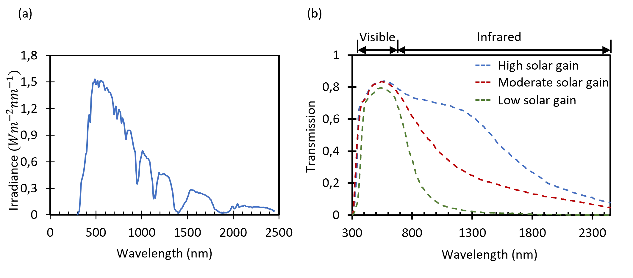
Science Exploration Style
Lober D, Hasan MK, Liebermann S, Iskhandar MSQ, Baby S, Chen JH, et al. MEMS smart glass for personalized lighting and energy management in buildings: working principles, characterization, active light steering, thermal management, energy saving considering different locations on earth, comparison of different smart glass technologies. J Build Des Environ. 2023;1:22962. https://doi.org/10.37155/2811-0730-0201-14
copy
Share Link
copy