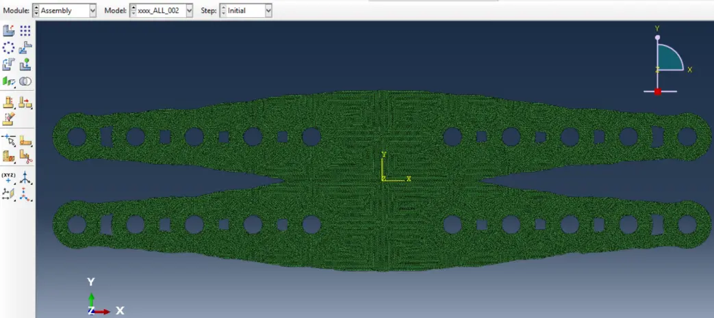
Abstract
Finite Element Method (FEM) is widely employed for solids and multiphysics problems analysis in practically all engineering and science fields. Yet, when it comes to Topology Optimization (TO), significant issues arise concerning the geometry, hence the mesh, and non-stationary condition. Contrarily to broader Finite Element Modelling, FEM for TO has much less bibliographic support and research. Herein we depict, apply and discuss the major challenges and options concerning modelling with finite elements within TO problems. It is shown that, for the optimisation of a steel connection part, mesh refinement is critical for effective yet computationally efficient analysis. Moreover, a case-based and user-friendly approach, in the form of a tutorial article, is proposed to address the practical FE meshing for TO.
Keywords
1. Introduction and Background
Computational methods have significant advantages over experimental studies for mechanical behaviour simulation and prediction[1], namely in terms of speed, cost and scale. Hence, numerical modelling has become indispensable in research[2-4], and frequently, the sole resource for development and design for engineering purposes. As a result, the Finite Element Method (FEM), due to its versatility in accurately simulating from simpler to more complex problems, is widely employed for solids and multiphysics analysis in virtually all engineering and science fields[5-7].
Nevertheless, Finite Element Analysis, especially nonlinear analysis (NLFEA), poses a critical hindrance to the design as mesh adequacy is frequently challenging to attain. It may be regarded as surprising—and a vital research gap—the lack of guidance for practitioners and researchers on this matter[8-12].
Topology Optimisation (TO) evolved from the Optimal Layout Theory as a tool to optimise structural elements’ shape and size and, very significantly, also its layout. Despite having its roots at the beginning of the twentieth century[13,14], it experienced significant developments in the last fifty years, firstly by Prager[15,16], and Rozvany[17-20], and afterwards with the homogenisation method for solving the material distribution problem, authored by Bendsøe, Kikuchi[11,21,22] and Suzuki, Kikuchi[23]. The research field was, therefore, founded and soon the first engineering applications in the aerospace industry followed. TO massification was pursued in the automotive industry, followed by the defence, medical devices, electronics and acoustics. Ultimately, civil engineering[24,25], multiple generative design endeavours[26] and material microstructures are facing a rapid surge in TO integration in design processes.
TO is, therefore, a critical asset for the future development of virtually all engineering fields. Yet, its current most representative application lies in steel parts design. Some recent publications on TO for steel structures include developments in structural systems[27], elements such as perforated beams[28] and shear walls[29], plates, for instance, with the Free Material Optimization method extension[30], and joints, as developed by Kanyilmaz and Berto[31,32], or spherical nodes[33].
The latest developments in civil and automotive engineering suggest that the generalised implementation of TO in design can only be achieved with the use of TO commercial software[34].
Yet, analogously to the NLFEA, a significant research gap can be identified in the lack of published literature concerning guidance, methods, and examples for TO in the context of steel structures, as well as in the optimisations limitation for nonlinear problems[35,36]. In fact, the topology’s continuum modification means that the mesh is non-stationary, raising an interesting nonlinear problem.
Moreover, options taken for boundary conditions will also play a critical role in the TO results[26]. Hence pre-processing and decision support are much needed to assist designers[26].
To address these shortcomings, the current article offers a detailed methodology for Nonlinear Finite Element modelling, validation, calibration and analysis, as well as for TO for stress minimisation of steel parts. Such an objective could only be pursued with an extensive and visual manuscript, which thoroughly depicts the approach and guides through parameters and options in a tutorial article format, but one that is fundamentally different from the available software tutorials. This is due to the underlying critical assessment and experience-based knowledge.
An example has been set in the Abaqus environment to allow for an integrated approach, as this software package enables sophisticated NLFEA while also running the TOSCA programme for TO[34-37]. Abaqus allows material and geometry NLFEA using Newton, modified Newton and quasi-Newton methods[38-40]. TOSCA Structure’s four optimisation modules, including Tosca Structure.shape, Tosca Structure.sizing, Tosca Structure.topology and Tosca Structure.bead. have been used for optimization practice and research in a broad range of engineering problems[29,34,36,41-50].
Presented in a more friendly format for practitioners and researchers, this tutorial article is structured to highlight methods on the one hand and results and discussion on the other, yet clearly separating the steps associated with NLFEA and TO, after defining the case study upon which the method illustration is unfolded. This structure is believed to provide the best assistance to the readers.
2. Methods
2.1 Case-study
To assist in the illustration of the modelling, optimisation and analysis steps, a case-study has been selected. Hence, the A572 Grade 50 steel plate depicted in Figure 1 has been considered.
This flange cover-plate in tension is 812.8 mm long, 12.7 mm thick, 205 mm wide and has twenty 20.7 mm diameter bolts. More details about this case-study connection can be found in a previous study from the authors[36].
2.2 Modelling and (material) nonlinear analysis
It should be noted that symmetry simplifications are possible and encouraged for nonlinear analyses, often offering significant computational efficiency gains without hindrances, but should be regarded with much more restraint for the TO tasks. Considering the Abaqus environment, the applied modelling method is initiated in the Global Standard/Explicit model menu, following by naming and saving the model in the folder to store the model files (“Set Work Directory”). It should be noted that, as by-standard, N, mm and MPa (N/mm2) units have been used.
The Module Part has been defined in “Create Part”. To define a plate under plane stress state, a coherent name of “Plate” has been defined, after which, “3D” has been chosen for Modelling Space, “Deformable” for Type, “Shell” for Shape in Base Feature and “Planar” for Type. The auxiliary grid approximate size has been defined as 1000 mm.
Using “Create Lines: Rectangle (4 lines)”, one could introduce the coordinates for the bottom left point “-406.4, -102.5” (Enter) and upper right point “406.4, 102.5” (Enter), considering the origin of the x-y reference frame set on the geometrical centre of the plate.
Auxiliary points are introduced at the centre and edge of the holes with “Create Isolated Point”.
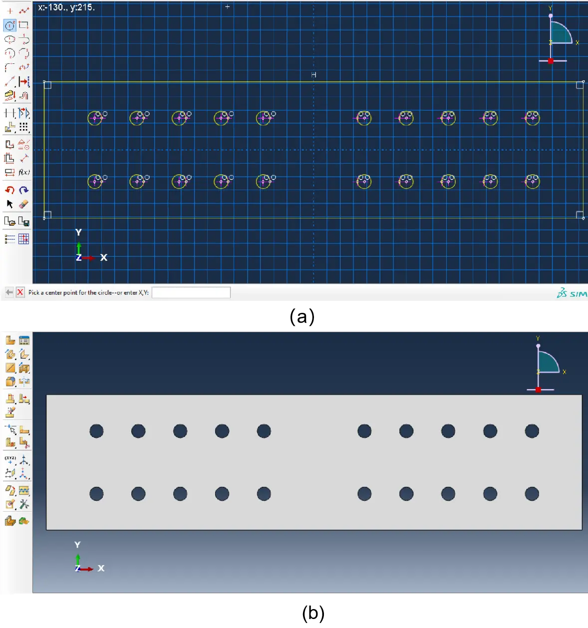
Using “Create Circle: Centre and Perimeter”, for each hole the coordinates of the centre point and one point on the perimeter are introduced to draw the circle. Alternatively, with “Create Isolated Point” one can introduce auxiliary points at the centre and edge of the holes and then use these points to draw the circles. The option “Linear Pattern” may assist in this task.
The plate’s complete geometry can now be defined Figure 2a, after which the procedure can be cancelled as reported in Figure 2b.
Partitions for the outer limit of the rings have been created with radius e1 = 24.84 mm. These rings are related with normative geometrical constrains for bolted connections and constitute non-optimisable domains of the steel plate[36]. For this, “Partition Face: Sketch” command has been used.
New circles have been drawn with rings’ outer limit radius of e1 = 24.84 mm in the Sketch module, using “Create Circle: Centre and Perimeter”. For each new circle hole the coordinates of the centre point have been introduced as well as one point on the perimeter to draw the circle (Figure 3a). Alternatively, using the previous “Create Isolated Point” one could introduce auxiliary points at the centre and edge of the holes and then use these points to draw the circles. Further assistance can be provided by the option “Linear Pattern”. As the option “Done” is activated, the geometry is defined as illustrated in Figure 3b.
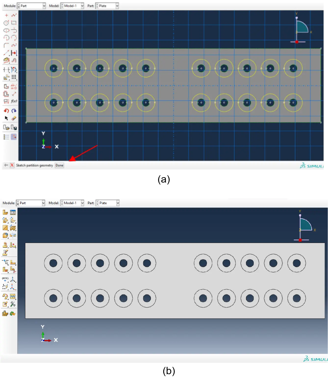
Figure 3. (a) Creating the limits for non-optimisable domains; (b) Created domains.
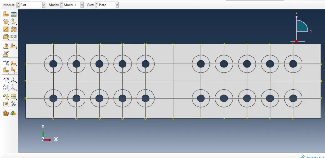
To Create Datum Points, one entered the coordinates at the edges (and pressed Enter), as reported in Figure 4. These Datum Points will be used as auxiliary points to create the additional partitions for meshing purposes. To create partitions with “Partition Face: Use Shortest Path between 2 Points”, we selected all the faces to partition before commanding “Done”. All faces have been manually selected. To create partitions with “Partition Face: Use Shortest Path between 2 Points”, we selected all the faces to partition before commanding “Done”. All faces have been manually selected. The step included selecting the start and end points and “Create Partition”. The formerly depicted step was repeated to create all partitions (using “Partition Face: Use Shortest Path Between 2 Points”), resulting in the geometry shown in Figure 4.
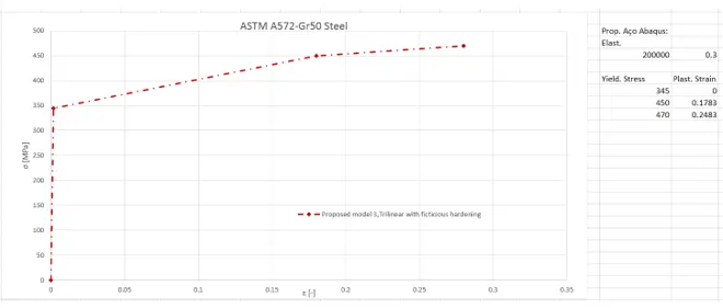
To insert the nonlinear material law within the Module Property, “Create Material” option has been selected. Within the former option, the A572-Gr50-Steel law (Figure 5) was initiated by selecting Mechanical, Elasticity and Elastic options and entering the value of 200 × 103 for Young’s Modulus and 0.3 for Poisson’s Ratio.
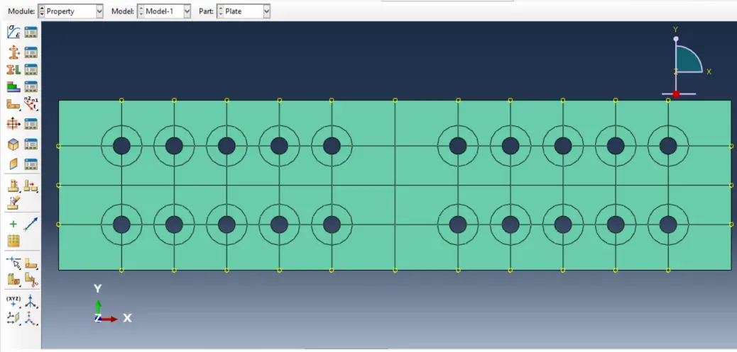
Within the “Create Section” option, a section named “plate” was created, and its Category (Shell) and type (Homogeneous) were defined, before continuing to enter 12.7 for the Shell thickness and selecting Material “A572-Gr50-Steel”. Therefore, the “Assign Section” option could be applied upon selecting the whole model and commanding “Done” (Figure 6).
The next step comprised to “Create Instance” in the Assembly Module. Likewise, in the Module Step the option “Create Step” has been activated to select the procedure type as “General”, and then “Static, General”. The value of 10,000 has been selected for the Maximum number of increments and 0.01 for Increment size Initial and Maximum.
Within the “Output”, “Field Output Requests”, and “Manager” fields, the “Edit” option has been selected, where “NFORC, Nodal forces due to element stresses” was determined. This will allow to compute and plot resultant forces from cut-lines defined by the user (in this case, the resultant tensile force in the plate).
At the Load Module two auxiliary datum coordinate systems were created in the centre of the holes (one from the upper line and another one from the bottom line, the rightmost ones) to define the load in the holes’ edges. For such an endeavour, “Datum CSYS: Offset From CSYS” was used. The first datum has been named “Datum csys-14” to ensure the same number as the centre point number of the hole. The procedure has been continued choosing the “Rectangular” option.
The principal datum csys has been defined as the reference one, “Select Point” has been selected. The centre point of hole 14 - the rightmost hole from the upper line - has been selected. The previous steps were repeated to create the “Datum csys-24” in the centre of hole 24 (the rightmost hole from the bottom line). The auxiliary datum coordinate systems expressed in Figure 7 were created.
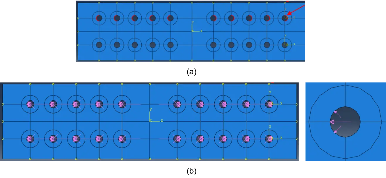
Bolt-hole contact fosters a sinusoidal loading pattern in the latter’s borders, as depicted in Figure 8. To create such sinusoidal loads in half of each holes’ edge, “Create Load” option in the Load Module is activated. The loading pattern has been named “Sinusoidal_upper”, where “Step-1” has been chosen. The Category has been set as “Mechanical”, and “Shell edge load” was the option for “Types for Selected Step”.
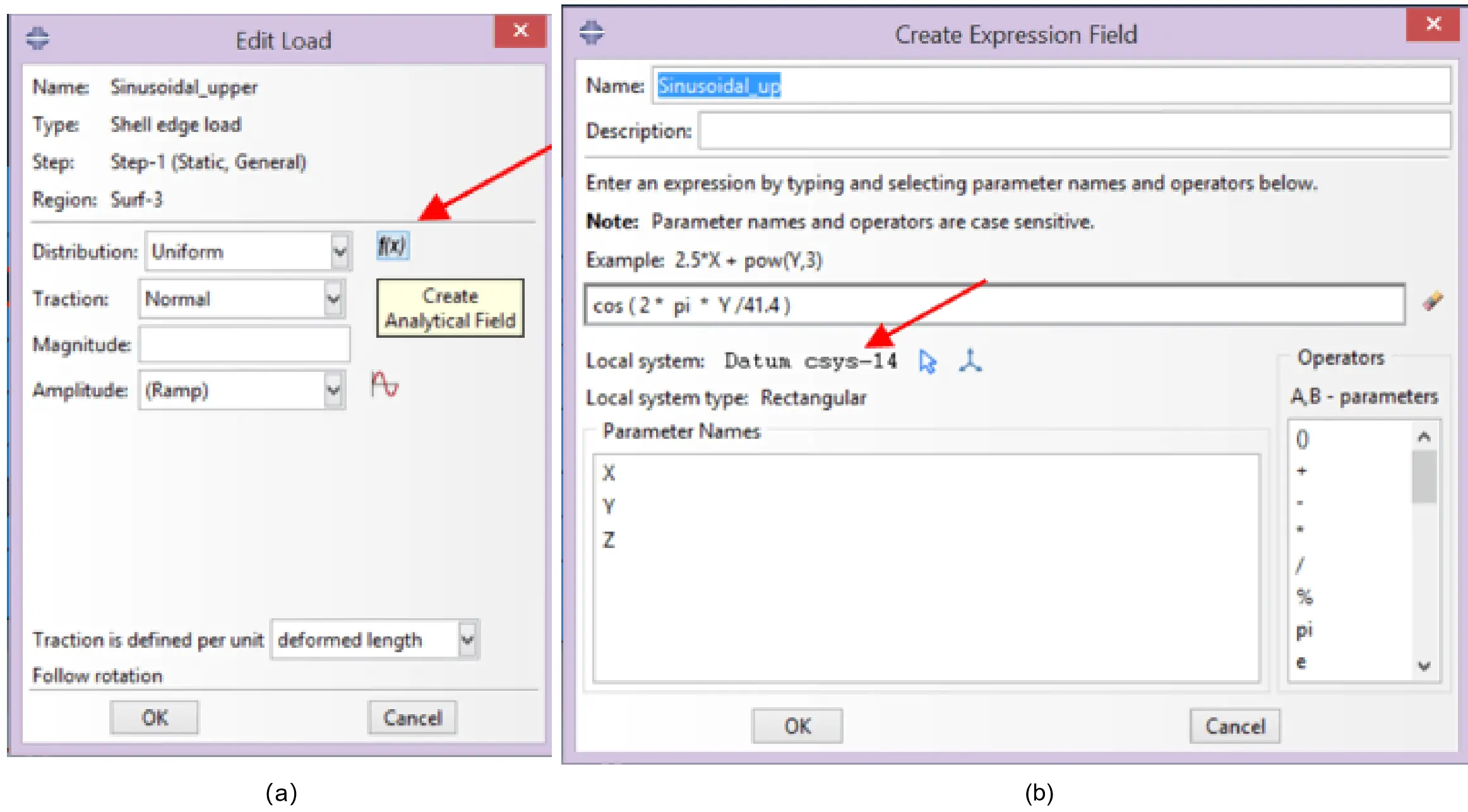
Upper half edges were selected for the load, as illustrated in Figure 9a. Followingly, “Create Analytical Field” was selected from the Edit Load (Figure 10a), where it was named “Sinusoidal_up” before choosing “Expression field” type. The analytical expression “cos (2*π*Y/41.4)” was then inserted, as expressed in Figure 10b. The “Edit” option had to be selected to indicate which local Datum csys will be used to define the load. For the case being, the previously defined Datum csys-14 (Figure 10a and Figure 9a).
In the Edit Load option, “Sinusoidal_up” was chosen, Traction was set as “Normal” and the Magnitude was defined as “5,700 N/mm”. The initial magnitude value is a reference value and should be set slightly higher than the initial design value, to be calibrated during incremental analyses. Analogous steps were followed to define the load in the half edges of the holes from the bottom line (Sinusoidal_bottom), using the Datum csys-24 as the auxiliary local datum coordinate system. The attained load layout is shown in Figure 9b.
In the Load Module, the “Create Boundary Condition” is activated. Then, “Restrain_U2” was created with the following properties: “Initial” step, “Mechanical” category and “Displacement Rotation” in the “Types for Selected Step” box.
The boundary condition in the bottom corners of the plate was then defined as restraining the vertical displacement U2. The previous steps were repeated to restrain the horizontal displacement (“Restrain_U1”, U1) in the middle point of the bottom horizontal edge of the plate (Figure 11).
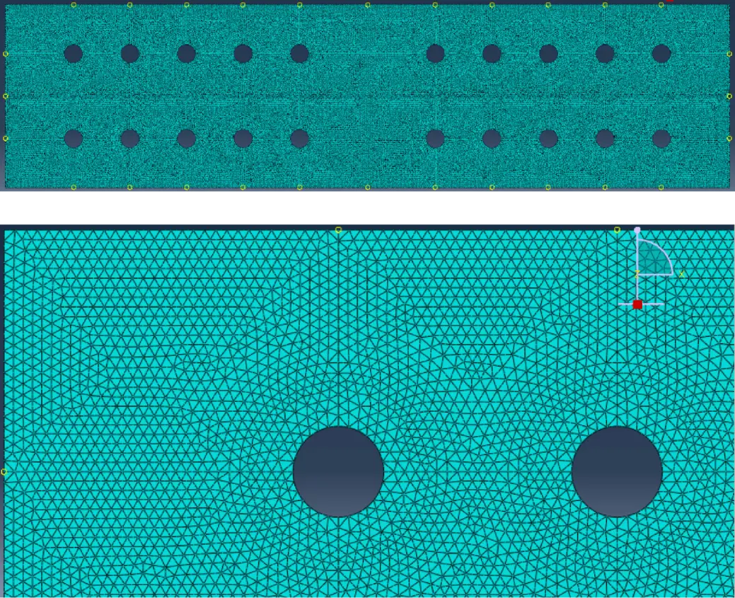
In the Mesh Module, the option “Part” was activated and “Seed Part” was selected. The approximate global size of 2.5 (mm) was entered. After activating “Assign Element Type” the whole model was selected.
Upon Element Type options, “Quadratic” Geometric Order, “Shell” Family and Triangular (Tri) element shape (STR65 Finite Element) have been chosen. After choosing “Assign Mesh Control” and selecting the entire model, the option “Tri” was designated for Element Shape and “Free” for Technique. The option “Mesh Part” was activated (and confirmed with “Yes” for “OK to mesh the part”), with the results shown in Figure 12.
Previous presented options related with the mesh density and mesh generation were chosen after some trials in order to obtain smooth perimeters after optimisation of the plate geometry.
In the Module Job the “Create Job” option was selected In “Parallelisation” page, the “Use multiple processors” was selected and “4” processors were declared to reduce the calculation effort. In the “Job Manager”, “Data Check” was selected to start the Analysis Input File and “Monitor…” to access the results. Errors and warnings were investigated in the dialogue boxes.
After solving any issue with the errors and warnings, the “Submit” option was activated in the “Job Manager” to start the Abaqus/Standard analysis. The “Monitor” was activated to follow the steps. After the analysis completion, the option “Results” allows accessing the “Visualisation” module, where the results can be visualised on the screen.
2.3 Topology optimization
The method for TO is conceived in the same Abaqus environment and built upon the already modelled geometry. It is initiated in the Global Standard/Explicit model and the previously prepared model is called. One should remind that the employed base units were N, mm and MPa (N/mm2).
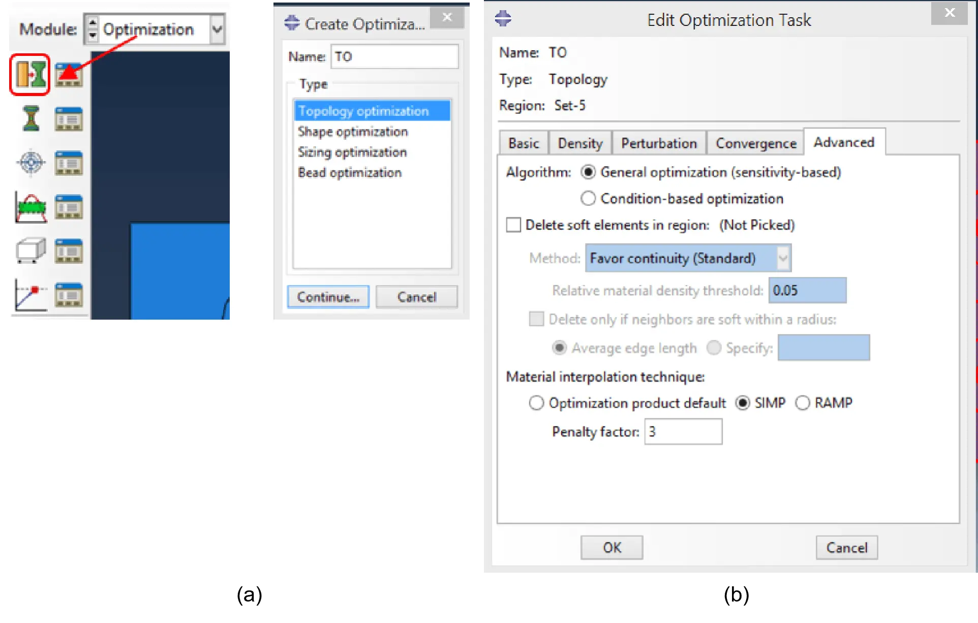
In the Optimisation module, the option “Create Optimisation Task” was taken, and the task was named “TO” (Figure 13a). The whole plate was then selected. In the “Edit Optimization Task”, the folder “Advanced” was opened, within which the Solid Isotropic Microstructure (or Material) with Penalisation “SIMP” method was chosen with as penalty factor of “3” (Figure 13b). The factor of three tops the range of 1-3 typically employed for structural engineering optimisation problems[51,52], and is usually regarded as the most suitable value.
In the optimisation module the option “Create Design Response” was chosen and named “Energ_Stiff”, under which “Single-term” was selected for the “Type” (Figure 14a). In the following step the whole model was selected (Figure 14b).
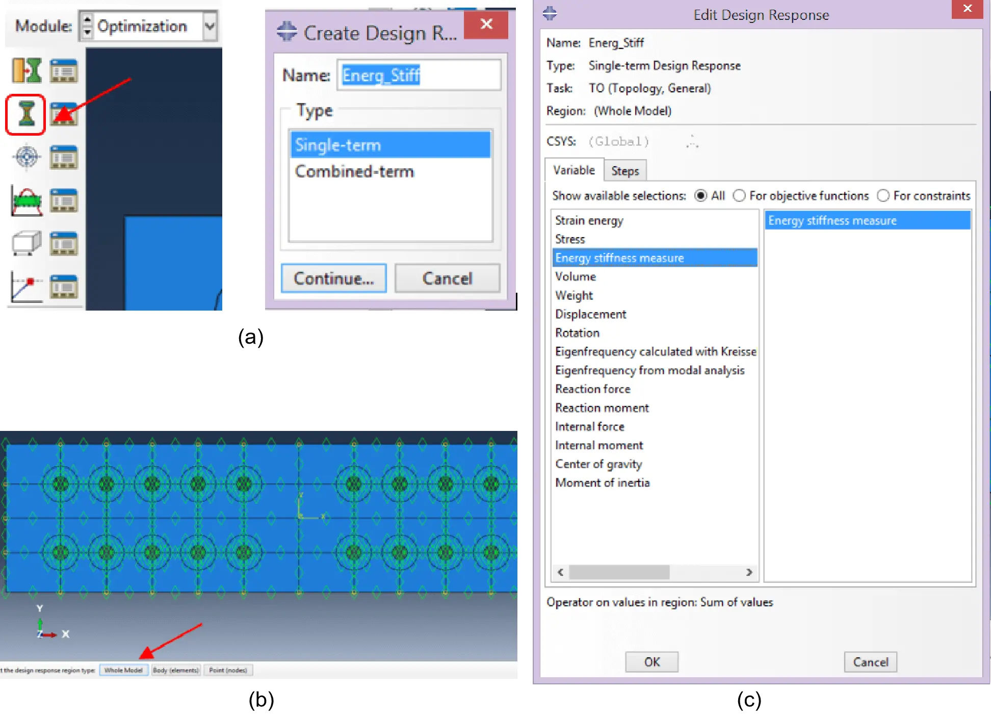
Figure 14. (a) Create design response; (b)Whole model selection; (c) Variable definition.
The “Energy stiffness measure” was chosen in the Edit Design Response dialogue box (Figure 14c). Using the Energy Stiffness Measure Minimization as the objective function is computationally very effective for extrema identification in systems under applied displacements and external loading. The Energy Stiffness Measure Minimization combines strain energy minimisation nodal loads and displacements product, regularly used for stiffness optimisation of systems subjected to external loading, with the strain energy maximisation of applied nodal displacements and reaction forces product, commonly used for optimisation problems under imposed displacements. Together, these two extrema finding techniques compose a resilient approach, with a broad application to computational optimisation of systems under several loading conditions.
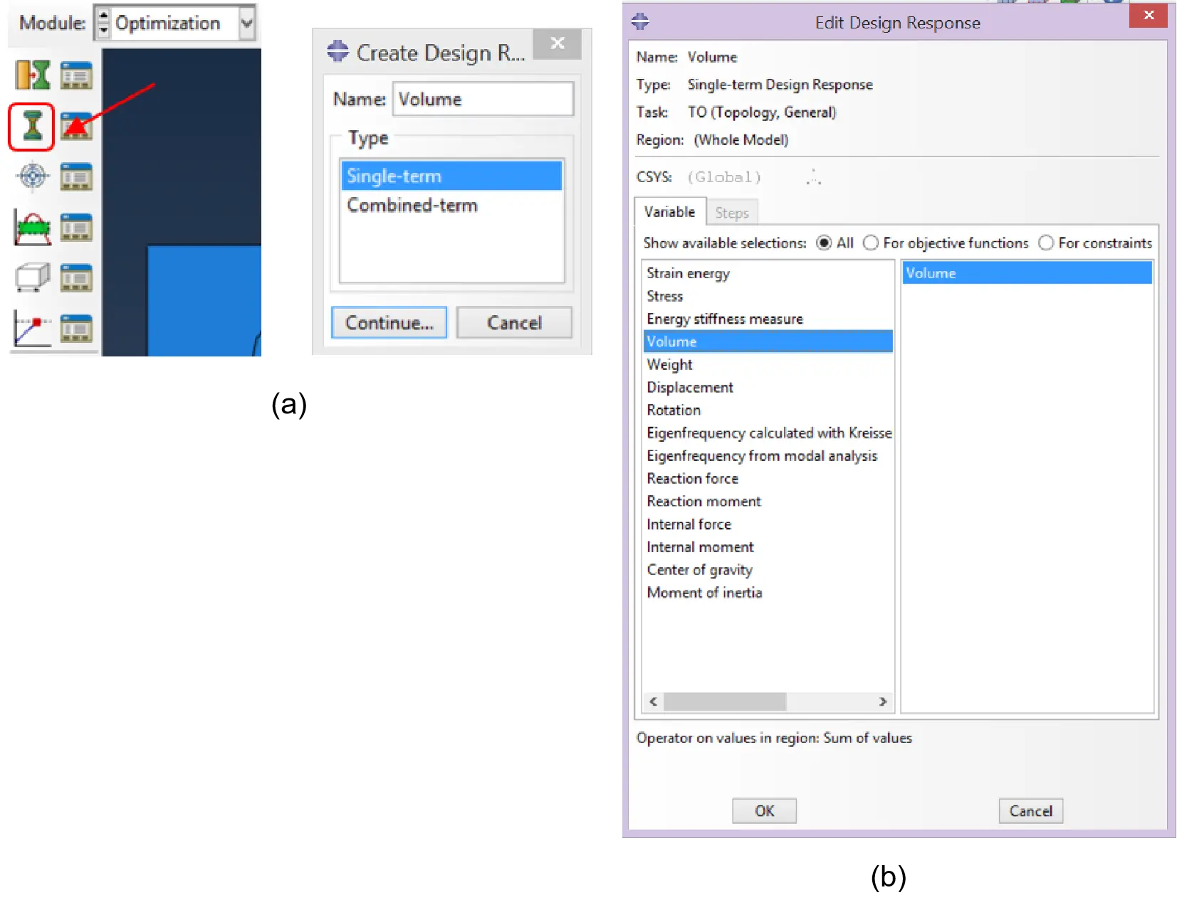
Within the optimisation module, “Create Design Response” option was selected and the name “Volume” was assigned. “Single-term” was chosen for the Type, as shown in Figure 15a. After selecting “Whole Model”, the “Volume” option was taken in the Edit Design Response dialog box, as reported in Figure 15b.
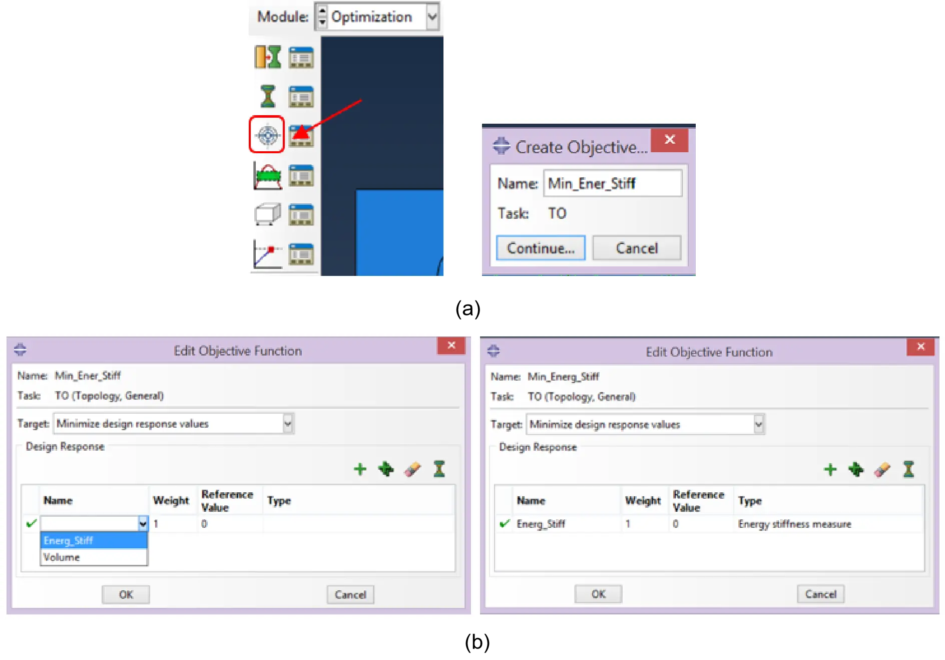
In the optimisation module, the “Create Objective Function” was activated to create a so-called “Min_Ener_Stiff” function (Figure 16a). In the “Edit Objective Function” dialogue box, “Minimise design response values” was chosen as the Target. To such an end, the blank cell “Name” was assigned with the option “Energ_Stiff” (Figure 16b).
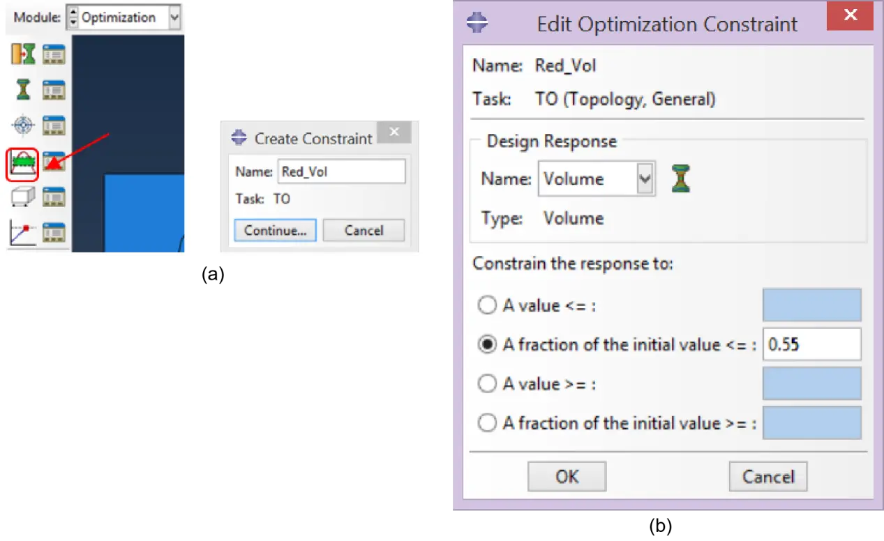
In the following step, a constraint is generated in the optimisation module using “Create Constraint”. The name “Red_Vol” was assigned (Figure 17a). In the “Edit Optimization Constraint” dialog box, the Design Response has been set as “Volume”, and “A fraction of the initial value” as “0.55” (Figure 17b). In a previous study from the authors[36], this value was found to be compatible with the normative design plate requirements.
The option “Create Geometric Restriction” was activated in the optimisation module (Figure 18a). Within such an option, the name “Freeze_Rings” has been stated as “Frozen area” was selected for the “Type” (Figure 18b). Hence, the created restriction was applied to the previously defined ring regions after a manual selection, ensuring that those will become the non-optimisable domain (Figure 18c).
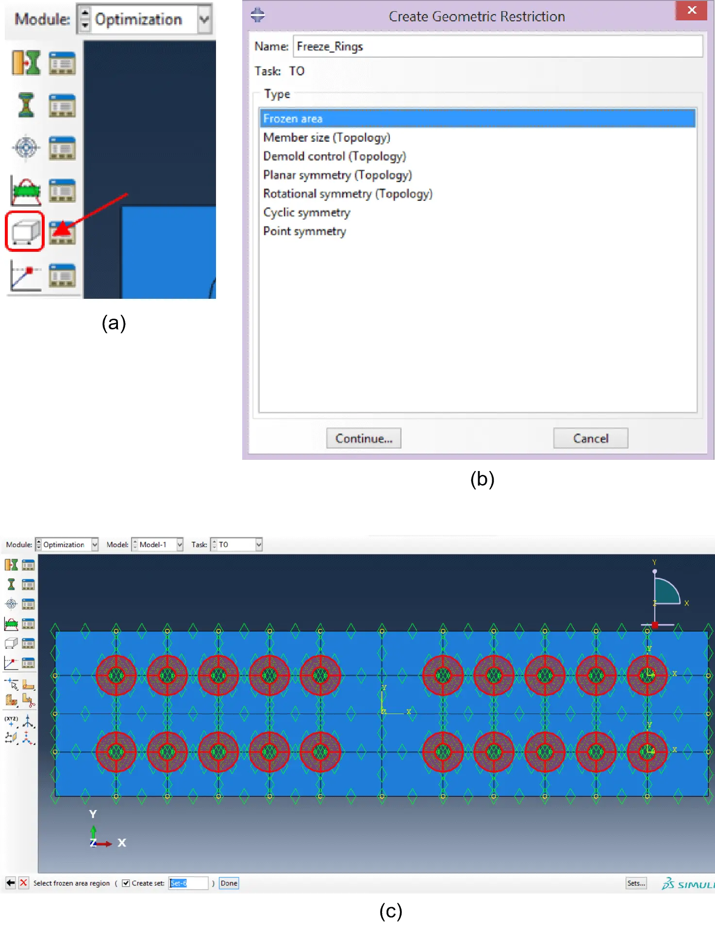
Figure 18. (a) Create geometric restriction; (b) Frozen area restriction; (c) Ring regions as non-optimisable domain.
The option “Create Geometric Restriction” was defined in the optimisation module (Figure 19a). Here, a “Planar symmetry” type was defined under the name of “Symmetry_xx” (Figure 19b) and the whole model was selected. In the “Edit Geometric Restriction”, after choosing Axis “1”, the coordinate system in the centroid of the plate (“Datum csys-1”) was assigned (Figure 19c). Therefore, the model will be optimised with an imposed symmetry with respect to the xx-axis of the coordinate system “Datum csys-1”.
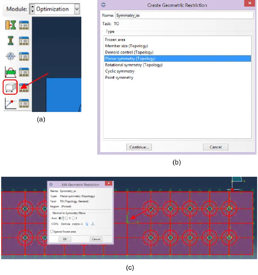
Figure 19. (a) Create geometric restriction; (b) Planar symmetry definition; (c) Edit geometric restriction.
The aforementioned steps were then repeated to impose symmetry with respect to the yy-axis of the coordinate system “Datum csys-1”. In the Job module, the option “Create Optimisation Process” was initiated (Figure 20a). Yet, to define the optimisation process, the “Edit Optimisation Process” dialog box had to be used. In the folder “optimisation” the value of “25” was chosen for the Maximum cycles and, in the folder “Parallelisation”, the option “Use multiple processors” was set and valued as “4”. Also in the Job module the “Optimization Process Manager” option was initiated. Here, the “Validate” command was used to start the Analysis Input File, while the “Monitor” option was used to investigate the results and check for errors and warnings.
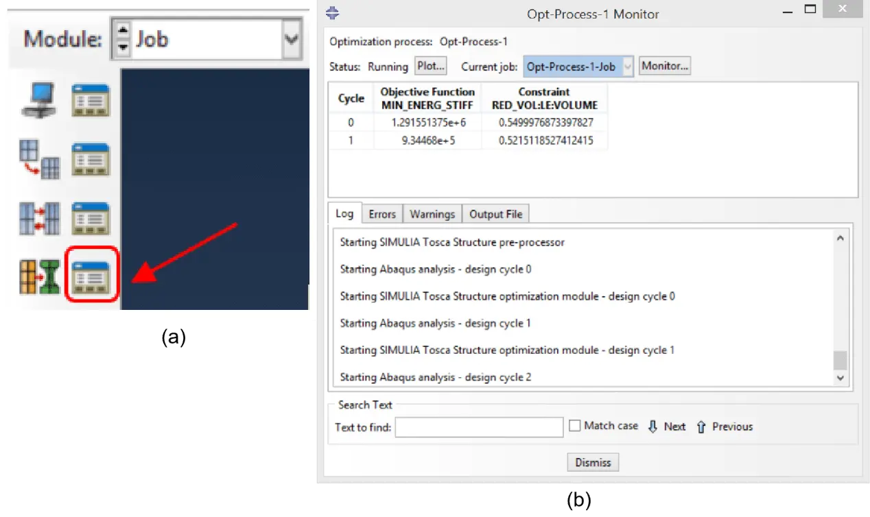
Figure 20. (a) Optimisation process manager; (b) Tosca structure pre-processor activation.
Upon confirming the absence of errors and standing warnings, the option “Submit” was selected in the “Optimization Process Manager” to start the Tosca Structure pre-processor and then “Monitor” to follow the cycles (Figure 20b). When submitting and before each cycle, the model was automatically analysed with Abaqus/Standard before Tosca Structure pre-processor was started. To stop the calculation procedure, in the Monitor dialogue box and the “Monitor” box, the “Kill” option was activated.
3. Results and Discussion
3.1 Nonlinear analysis
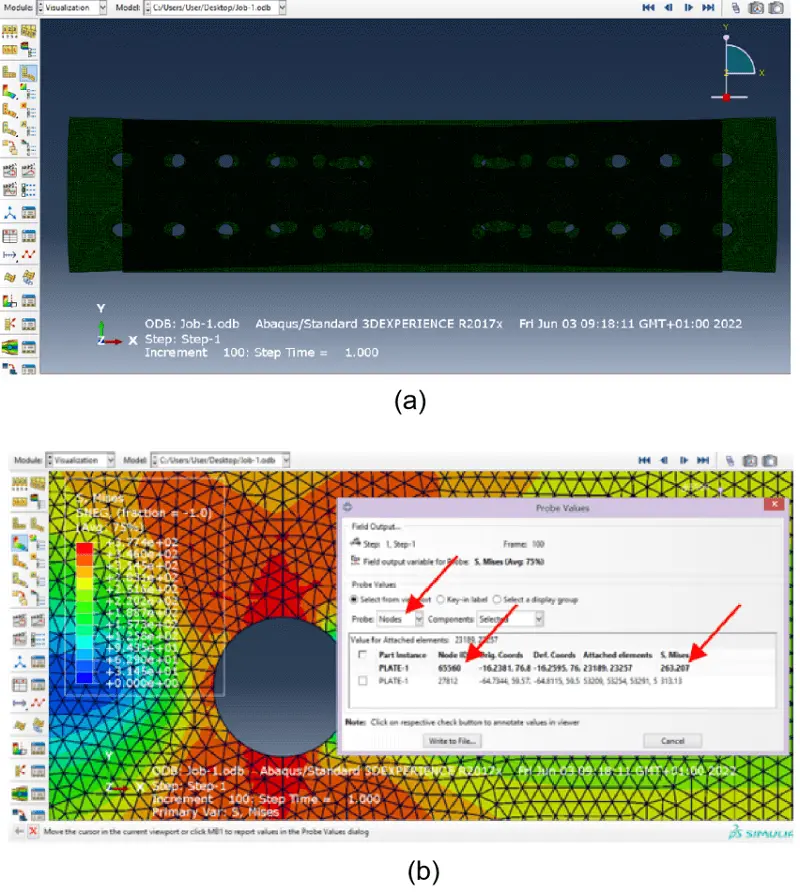
The visualisation of the results accomplished with the formerly depicted methodology was performed in the “Visualisation” module, as exemplified in Figure 21a for the plate deformation.
It is also possible to visualise the (von Mises) stress resultant in a particular node. For this, “Query information” option is accessed in the toolbars, “Probe values” is selected for Visualization Module Queries and “Nodes” for the Probe. Upon selecting a node, the S. Mises stress value is shown (Figure 21b).
In order to plot the results, first “Create XY Data” was activated and “OBD field output” was chosen. In the “Variable” fold, “Unique Nodal” is chosen for Position, and “U: Spatial displacement – U1” is selected. Afterwards, on the Elements/Nodes page, “Pick from viewport” is chosen for the Method, and the chosen node in the right edge was selected to Plot. This allows to show in the screen a graph with the calculation reference Time in abscissa and Displacement (mm) in ordinate.
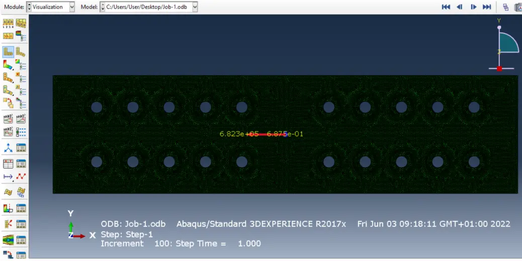
The attained tensile force of the plate corresponds to the resultant along a vertical cut-line located in the middle of the plate. To compute this tensile force and draw the plot, one can select “Create Free Body Cut”, and choose “Elements and nodes”. On “Create XY Data”, choosing “OBD field output”, one can select “Elements” for the Item and “Pick from viewport” for the Method. All the Finite Elements at one side (in this case the right side) were manually selected along the vertical cut-line (for such an end the tools “Box Zoom View” and “Pan view” were used along with “SHIFT”, to add, + “CTRL”, to deselect).
Then, the options “Nodes” is selected for the Item and “Pick from viewport” for the Method. All the nodes along the vertical cut plane are selected (to such an end, “Box Zoom View” and “Pan view” are employed, as well as “SHIFT” + “CTRL” commands). “Centroid of cut” and “CSYS” are selected in the Edit Free Body Cut dialogue box. The vectors for the resultant forces can now be viewed on the screen, with their respective numerical value for the last step (Figure 22).
In the “Free Body Cut Manager” a choice was made to visualise only the longitudinal force. Hence, in the dialogue box, under “Options”, only “Show forces” were selected and only Component “1” in the “Colour & Style”. “Free body” is chosen within “Create XY Data”. “Force” for Entity and “1-component” for Force/Moment Components were chosen before generating the plot, with the calculation reference Time in abscissa and Tensile force (N) in ordinate. The values for the longitudinal tensile force can be visualised and copied in the same way as previously explained for the displacement.
Further on, to draw the “axial force” - “displacement” plot, the “Create XY Data” option was activated and “Operate on XY data” was chosen. Given that data for the longitudinal tensile force was already available since it was created previously, data for the displacement was the only need. Therefore, the “Create XY Data” option was taken, and the Create XY Data dialogue box became accessible. “ODB field output” was chosen, and the steps previously presented to generate the U1 displacement data for one node were replicated. Next, in the Operate on XY Data dialogue box, two data sets became available to be plotted: Longitudinal tensile force + U1 Displacement. The name of the data sets in the left menu can be changed by selecting the set.
With Operators’ assistance and selecting the datasets’ names, the expression depicted in Figure 23a was inserted. One should note that the values for the longitudinal force were multiplied by -1 to ensure positivity. Subsequently, the plot was drawn with “Plot Expression”, as illustrated in Figure 23b. The values for the longitudinal tensile force and displacement can be visualised and copied in the same way as previously explained for the displacement.
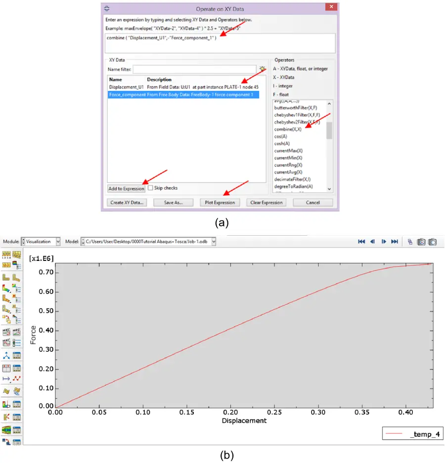
Figure 23. (a) Setting the conditions for the Longitudinal tensile force + U1 Displacement plot; (b) Longitudinal tensile force + U1 Displacement plot.
A non-linear analysis of the non-optimized plate ran either in an Intel(R) Core(TM) i7-4700MQ CPU @ 2.40 GHz processor or in a CPU @ 2.40 GHz e AMD Ryzen 7 5700U @ 1.80 GHz 16 Gb RAM processor took 28 minutes to converge for a full-plate model with a 2.5 mm spacing mesh and 0.5% step increments. On the other hand, a partial (double-symmetrical) model took 10 minutes to garner the solution.
The results show that the critical challenges in nonlinear FEM for steel parts are mostly mesh adequacy and difficulty analysing large amounts of data. Concerning the former, mesh convergence studies arise as an absolute necessity to ensure the proper refinement for efficient computing. Regarding the latter, it has been shown that choosing the most adequate points from which data should be systematically extracted is crucial to allowing efficient knowledge extraction.
Considering that numerical estimation models are insurmountable when experimental data is not possible to obtain[53], and that is certainly the case of computational TO, conceiving and validating an adequate FE model beforehand is a mandatory step to ensure the optimised model validation.
3.2 Results of topology optimization
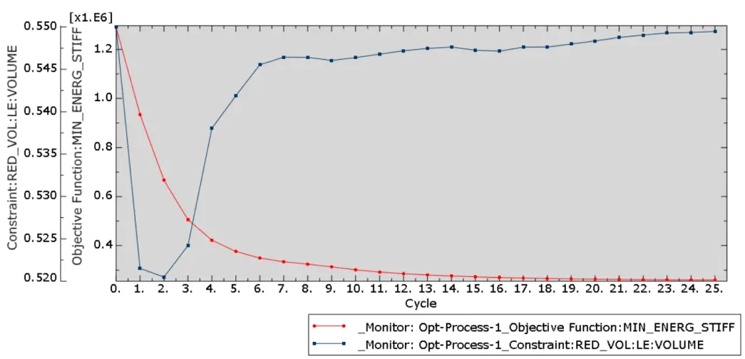
During or at the end of the optimisation calculation procedure, the option “Plot” can be activated (Figure 20b) to visualise the evolution of both the constraint parameter and the objective function (Figure 24).
The plot data can be visualised and copied from the “Results” menu, as previously explained for the tensile force – deformation plot.
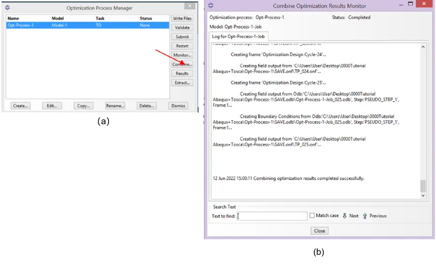
After completion, “Combine” option (Figure 25a) must be used to combine the optimisation results from each cycle (Figure 25b). The successive options Submit and Close must be taken.
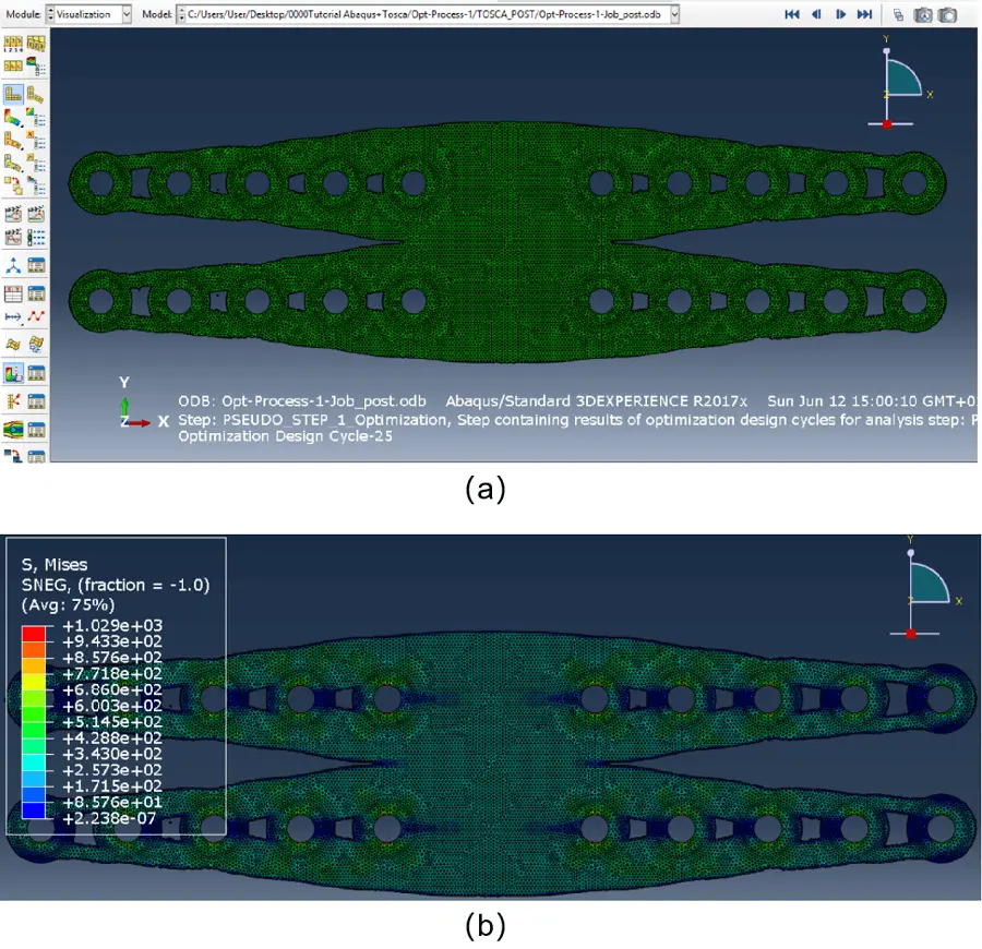
The visualisation is then accomplished through “Results” in the Optimization Process Manager. Within the “Visualisation” module, the results can be seen on the screen (Figure 26a,b).
To extract the optimised surface mesh, one can access the Job module and select the “Optimisation Process Manager” (Figure 20a).
The “Extract” option in the Optimization Process Manager (Figure 25a) can be utilised to export a smooth (filtered) optimised surface mesh. On the “Extract Surface Mesh” dialogue box, “Opt_surface” can be entered as Output name (Figure 27a). Choosing “STL” format will generate an additional STL file which is compatible with CAD systems or converted to DXF or DWG formats with a converter. Moreover, an INP format Abaqus input file will also be generated. Iso value was set to “0.2” and Filtering to “Moderate” (Figure 27a). From the generated STL file (or the converted file to DXF/DWG) the smooth optimised surface mesh can be imported into CAD software and further processed (Figure 27b).
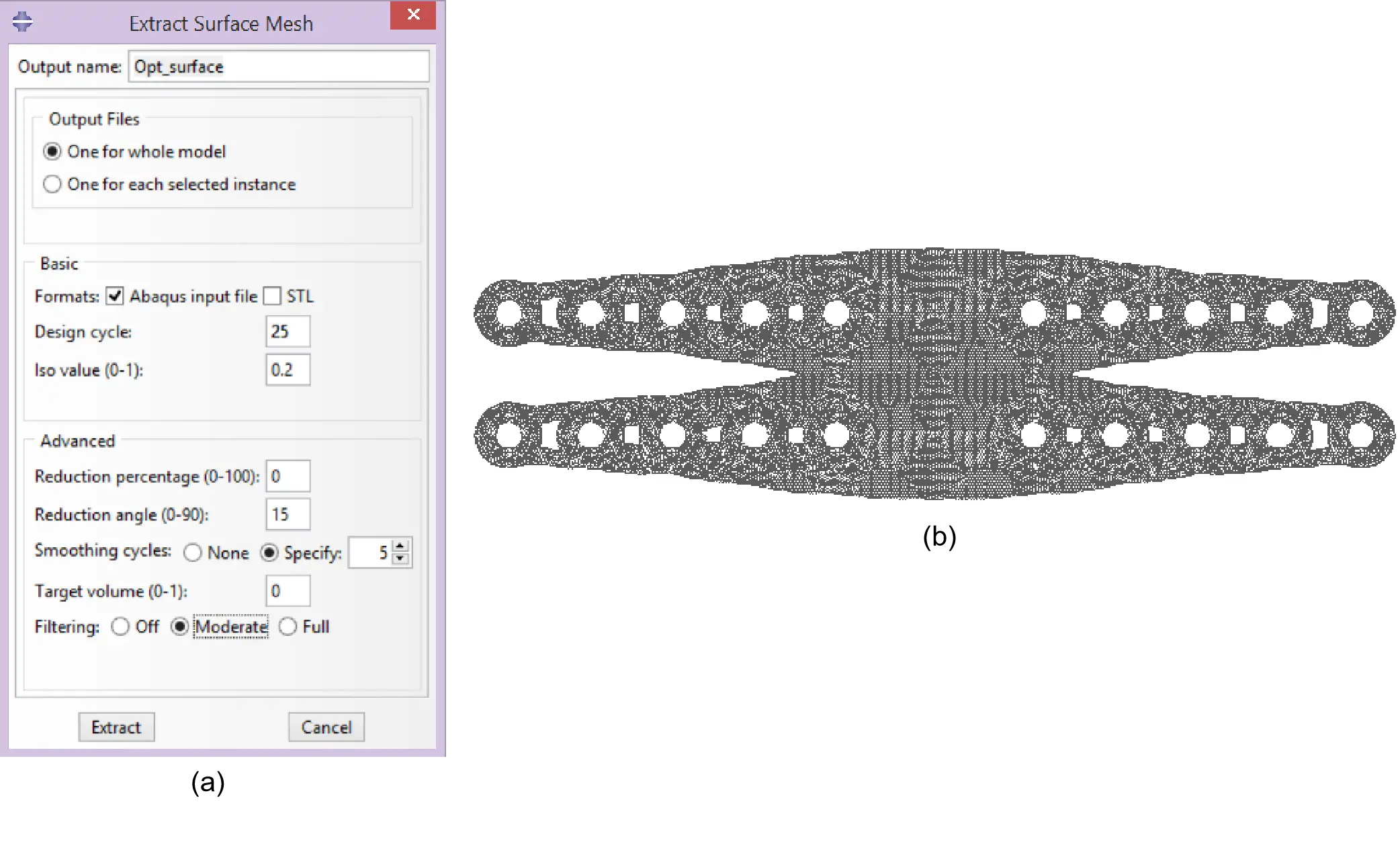
Figure 27. (a) Defining option for the mesh extraction; (b) Converting the extracted mesh into a CAD model. CAD: computer aided design.
Henceforth, it is possible to import the optimised geometry into Abaqus and remesh the smooth optimised surface mesh from the previously exported INP format file (Abaqus input file). To such an end, a simulation shall be initiated in Global Standard/Explicit model. Therefore, the sequence of commands File, “Import” and “Model” shall be pursued, after which *.inp” is chosen in the File Filter to select the file to open. The model shall now be renamed.
Hence, a raw surface mesh, with no material properties, loadings, or boundary conditions is attained (Figure 28). It is important to note that since the surface mesh was imported, an “Instance” already exists, thence there is no need to “Create Instance” in the module “Assembly”.
In the “Mesh” module “Part” is selected as the Object. The Finite Elements’ Geometric Order was changed to Linear as default. Hence, it is necessary to “Assign Element Type” and select the whole model to change the FE properties as required.
For the case being study, as for most optimisation cases, distorted Finite Elements can be visualised in the contour regions of the model (Figure 29a), which can lead to numerical problems. To solve this issue, in Module Mesh the “Edit Mesh” option was accessed, where “Refinement” was set as Category and “Set size” as Method. The desired mesh density, of “2.5” mm, for this specific case, was inserted. Accessing again the “Edit Mesh” dialogue box, one may select “Refinement” as Category and “Remesh” as Method (Figure 29b). After the mesh regeneration, the issues were corrected, as depicted in Figure 29c. It is important to stress out that the mesh refinement may cause some partition lines and curves (for instance the circular outer limit of the rings) to be lost.
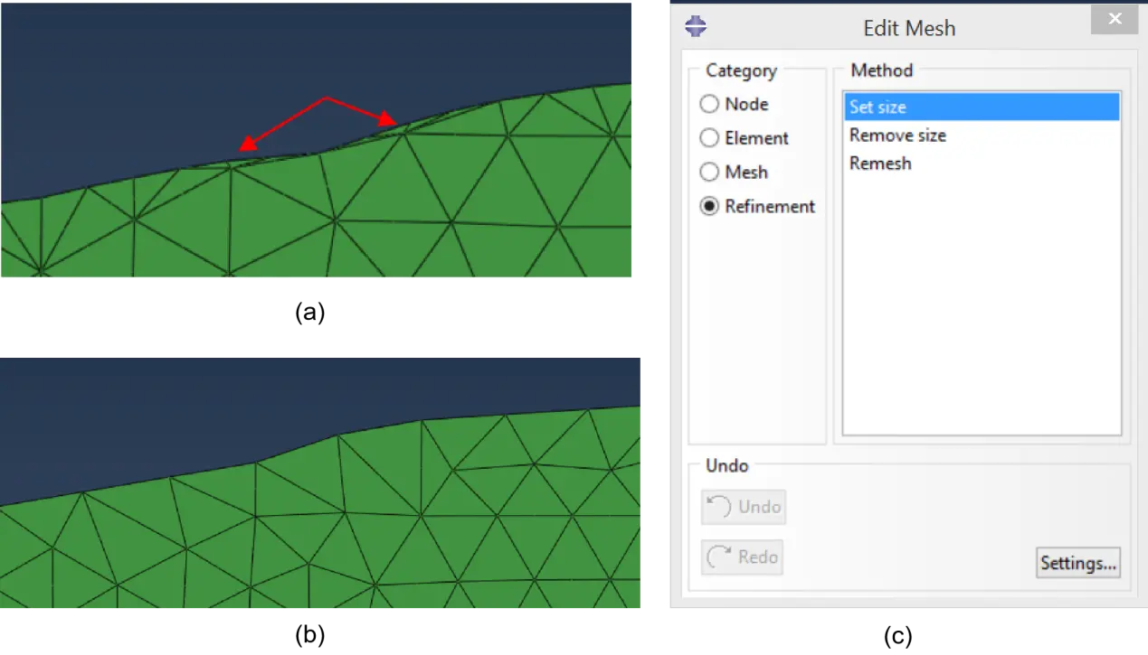
Figure 29. (a) Distorted finite elements, (b) Edit mesh for refinement; (c) Refined finite elements.
To perform a nonlinear analysis, the model is can be simplified accounting for symmetry conditions. Therefore, the model reduction to one-fourth of its initial size is enabled by the symmetry conditions. To such an end, in the “Edit Mesh”, “Element” was selected as Category and “Delete” as Method. After the options were set, the region to be deleted was selected, so that the analysis model depicted in Figure 30a was attained. To renumber the Finite Elements, in the “Edit Mesh” option (Figure 29b), “Element” is selected as Category and “Renumber” as Method. Afterwards, in the “Element Renumbering” dialogue box, “1” is entered as start Label and “All” the Domain is selected. After this, it is advisable to choose “Assembly” as the Object and choose “Regenerate” in “Feature” menu, in order to regenerate the assembly in order to avoid out-of-date assemblies in the model.
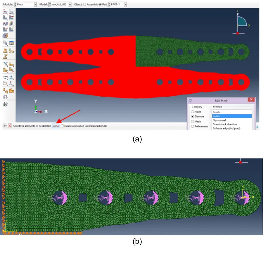
Figure 30. (a) Deleted and analysis regions accounting for the symmetry conditions; (b) Loading and boundary conditions.
The final step is applying loading and boundary conditions (accounting for the symmetry conditions) to the simplified model, and perform a (material) nonlinear analysis, in the same way as previously performed with the whole plate. Since the current case pertains to an imported mesh, surface, material properties, loading and boundary conditions must be defined directly in the mesh surface.
In Figure 30b, loading and boundary conditions in the simplified model are shown. Hence, a sinusoidal loading is applied in half the perimeter of the holes’ edges (magnitude of the load = 6,250 N/mm.), U2 displacement (yy) is restrained along the bottom horizontal border and U1 displacement is restrained along the left vertical border. Analysis results are depicted in Figure 31a,b,c,d.
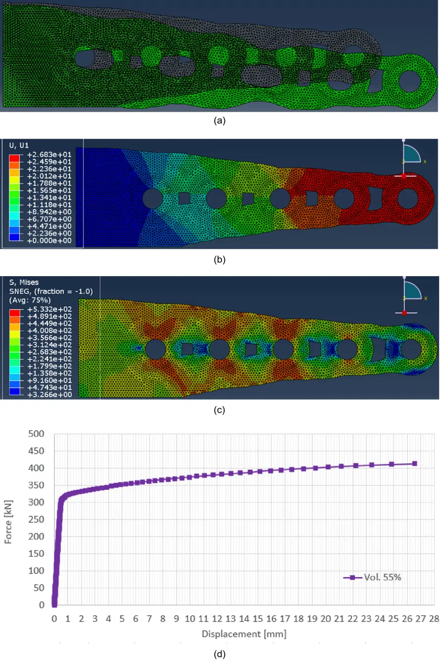
Figure 31. Analysis results: (a) deformed shape; (b) U1 (xx) displacements map [mm]; (c) Von Mises stress map [MPa]; (d) Force-deformation plot.
The optimization task ran both in an Intel(R) Core(TM) i7-4700MQ CPU @ 2.40 GHz processor and in a CPU @ 2.40 GHz e AMD Ryzen 7 5700U @ 1.80 GHz 16 Gb RAM processor, took 25 cycles to meet the established convergence goals, even if after the first 12 cycles the solution was practically stable. The computing time was very heterogenous among cycles, being the ones near convergence much faster. Hence, establishing an ambitious number for cycles as a minimum shall not have a critical impact on the computing time.
The results highlight the particular challenges of FEM for TO. The fact that, as the optimisation process unfolds, the geometry is ever-changing means that remeshing is a perennial need. Minor but continuous, modifications to the shape borders significantly increase the likelihood of distorted meshes. Therefore, one shall wonder if the model update along the optimisation procedure guarantees a proper mesh, especially in the shapes’ edges. Nevertheless, upon finishing the optimisation, a full remesh is advised, notwithstanding the herein depicted fact that the geometry export and import procedure is laborious and prone to human errors. It is shown that, for the optimisation of a steel connection part, mesh refinement is critical for effective yet computationally efficient analysis.
4. Conclusions
Topology Optimisation is still far from being a widespread resource for design and research for marine structures. A critical factor concurring to this reality is the lack of procedures and methodologies to allow the practical employment of TO with commercial software.
To overcome this gap, we herein offer a rare and extremely detailed and user-friendly methodology both for TO and nonlinear finite element analyses of optimised plates, using the Abaqus environment, including computing time.
The inclusion of NLFEA is critical, since it has been shown that optimisations performed under elastic conditions may not be safe-sided regarding the parts’ ultimate capacity[36] and, therefore, need a further NL assessment. This is a very significant finding.
With the current investigation, it has also been concluded that mesh convergence studies are strongly advised as preliminary steps for TO and NLFEA, that a wise choice of reference points for data extraction is fundamental for being able to deal with the big data generated by the NLFEA and that remeshing and controlling mesh distortions is a critical challenge along the optimisation process.
Hence, regardless of the employed optimisation software, the issue of continuous remeshing throughout the TO process shall be closely followed.
Authors contribution
Bernardo L: Conceptualization, methodology, software, formal analysis, resources, data curation, writing-original draft preparation, writing-review and editing, visualisation, supervision.
Ribeiro T: Methodology, validation, formal analysis, writing-original draft preparation, writing-review and editing, visualisation.
All authors have read and agreed to the published version of the manuscript.
Conflicts of interest
The authors declare no conflicts of interest.
Ethical approval
Not applicable.
Consent to participate
Not applicable.
Consent for publication
Not applicable.
Availability of data and materials
Not applicable.
Funding
None.
Copyright
© The Author(s) 2023.
References
-
1. Rabiee A, Ghasemnejad H. Finite Element modelling approach for progressive crushing of composite tubular absorbers in ls-dyna: Review and findings. J Compos Sci. 2022;6(1):11.[DOI]
-
2. Šimůnek J, Genuchten MT, Šejna M. Development and applications of the HY-DRUS and STANMOD software packages and related codes. Vadose Zo J. 2008;7(2):587-600.[DOI]
-
3. Böl M, Ehret AE, Bolea Albero A, Hellriegel J, Krull R. Recent advances in mechanical characterisation of biofilm and their significance for material modelling. Crit Rev Biotechnol. 2013;33(2):145-171.[DOI]
-
4. Vinogradov A, Estrin Y. Analytical and numerical approaches to modelling severe plastic deformation. Prog Mater Sci. 2018;95:172-242.[DOI]
-
5. Sigmund O. Design of multiphysics actuators using topology optimization - part I: One-material structures. Comput Methods App Mech Eng. 2001;190(49-50):6577-6604.[DOI]
-
6. Sigmund O. Design of multiphysics actuators using topology optimization - part II: Two-material structures. Comput Methods Appl Mec Eng. 2001;190(49-50):6605-6627.[DOI]
-
7. Deaton JD, Grandhi RV. A survey of structural and multidisciplinary continuum topology optimization: Post 2000. Struct Multidiscip Optim. 2014;49:1-38.[DOI]
-
8. Crisfield MA, Tassoulas JL. Non‐linear finite element analysis of solids and structures. J Eng Mech. 1993;119(7):1504-1505.[DOI]
-
9. De Borst R, Crisfield MA, Remmers JJC, Verhoosel CV. Nonlinear finite element analysis of solids and structures. John Wiley & Sons; 2012.
-
10. Voyiadjis GZ, Woelke P. General non-linear finite element analysis of thick plates and shells. Int J Solids Struct. 2006;43(7-8):209-2242.[DOI]
-
11. Sousa AM, Azevedo L, Pereira MJ, Matos HA. The influence of solar heating upon ground temperature. J Phys: Conf Ser. 2021;2116(1):012120.[DOI]
-
12. Gaur H. A new approach of material nonlinear finite element analysis. Def Technol. 2020;2:18.[DOI]
-
13. Michell AGM. The limits of economy of material in frame-structures. London Edinburgh Dublin Philos Mag J Sci. 1904;8(47):589-597.[DOI]
-
14. Hegemier GA, Prager W. On Michell trusses. Int J Mech Sci. 1969;11(2):209-215.[DOI]
-
15. Prager W. A note on discretized michell structures. Comput Methods Appl Mech Eng. 1974;3(3):349-355.[DOI]
-
16. Prager W, Rozvany GIN. Optimization of structural geometry. In: Bednarek AR, Cesari L, editors. Dynamical systems. New York: Academic Press; 1977. p. 265-293.[DOI]
-
17. Rozvany GIN. Grillages of maximum strength and maximum stiffness. Int J Mech Sci. 1972;14(10):651-666.[DOI]
-
18. Rozvany GIN. Optimal load transmission by flexure. Comput Methods Appl Mech Eng. 1972;1(3):253-263.[DOI]
-
19. Rozvany GIN, Zhou M, Rotthaus M, Gollub W, Spengemann F. Continu-um-type optimality criteria methods for large finite element systems with a displacement constraint. Part I. Struct Optim. 1989;1:47-72.[DOI]
-
20. Rozvany GIN, Zhou M, Gollub W. Continuum-type optimality criteria methods for large finite element systems with a displacement constraint. Part II. Struct Optim. 1990;2:77-104.[DOI]
-
21. Bendsøe MP, Kikuchi N. Generating optimal topologies in structural design using a homogenization method. Comput Methods Appl Mech Eng. 1988;71(2):197-224.[DOI]
-
22. Bendsøe MP. Optimal shape design as a material distribution problem. Struct Optim. 1989;1:193-202.[DOI]
-
23. Suzuki K, Kikuchi N. Shape and topology optimization by a homogenization method. Am Soc Mech Eng Appl Mech Div AMD. 1990;115:15-30.
-
24. Pedersen P. On the optimal layout of multi-purpose trusses. Comput Struct. 1972;2(5-6):695-712.[DOI]
-
25. Kirsch U. Optimal topologies of truss structures. Comput Methods Appl Mech Eng. 1989;72(1):15-28.[DOI]
-
26. Tyflopoulos E, Steinert M. Messing with boundaries-quantifying the potential loss by pre-set parameters in topology optimization. Procedia CIRP. 2019;84:979-985.[DOI]
-
27. Angelucci G, Spence SMJ, Mollaioli F. An integrated topology optimization framework for three‐dimensional domains using shell elements. Struct Des Tall Spec Build. 2021;30(1):e1817.[DOI]
-
28. Tsavdaridis KD, Kingman JJ, Toropov VV. Application of structural topology optimisation to perforated steel beams. Comput Struct. 2015;158:108-123.[DOI]
-
29. Bagherinejad MH, Haghollahi A. Study on topology optimization of perforated steel plate shear walls in moment frame based on strain energy. Int J Steel Struct. 2020;20(4):1420-1438.[DOI]
-
30. Weldeyesus AG, Stolpe M. Free material optimization for laminated plates and shells. Struct Multidiscip Optim. 2016;53(6):1335-1347.[DOI]
-
31. Kanyilmaz A, Berto F. Robustness‐oriented topology optimization for steel tubular joints mimicking bamboo structures. Mater Des Process Commun. 2019;1(1):e43.[DOI]
-
32. Kanyilmaz A, Berto F, Paoletti I, Caringal RJ, Mora S. Nature-inspired optimiza-tion of tubular joints for metal 3D printing. Struct Multidiscip Optim. 2020;63:767-787.[DOI]
-
33. Hassani V, Khabazi Z, Mehrabi HA, Gregg C, O’Brien RW. Rationalization algo-rithm for a topologically-optimized multi-branch node for manufacturing by metal printing. J Build Eng. 2020;29:101146.[DOI]
-
34. Ribeiro T, Bernardo L, Andrade J. Topology Optimisation in structural steel design for additive manufacturing. Appl Sci. 2021;11(5):2112.[DOI]
-
35. Lange J, Feucht T, Erven M. 3D printing with steel: Additive manufacturing for connections and structures. Steel Constr. 2020;13(3):144-153.[DOI]
-
36. Ribeiro T, Bernardo L, Carrazedo R, De Domenico D. Eurocode-compliant topology optimisation and analysis of a steel cover-plate in a splice moment connection. Mater Today Proc. 2022;65:1056-1063.[DOI]
-
37. Dassault Systèmes Tosca Structure. Users’ Guide, 2014.
-
38. Wang Y, Pasiliao CL. Modeling ablation of laminated composites: A novel manual mesh moving finite element analysis procedure with ABAQUS. Int J Heat Mass Transf. 2018;116:306-313.[DOI]
-
39. Lee SH, Abolmaali A, Shin KJ, Lee HD. ABAQUS modeling for post-tensioned reinforced concrete beams. J Build Eng. 2020;30:101273.[DOI]
-
40. Yussof MM, Silalahi JH, Kamarudin MK, Chen PS, Parke GAR. Numerical evaluation of dynamic responses of steel frame structures with different types of haunch connection under blast load. Appl Sci. 2020;10(5):1815.[DOI]
-
41. Matos M. Sizing Optimization for Industrial Applications. In: Proceedings of the 11th World congress on structural and multidisciplinary optimization (WCSMO-11); 2015 June 7-12; Sydney, Australia. 2015.[DOI]
-
42. Pedersen CBW, Allinger P. Industrial implementation and applications of topology optimization and future needs. In: Bendsøe MP, Olhoff N, Sigmund O, editors. IUTAM Symposium on Topological Design Optimization of Structures, Machines and Materials. Springer: Dordrecht; 2006. p. 229-238.[DOI]
-
43. Rozvany GIN. A critical review of established methods of structural topology optimization. Struct Multidiscip Optim. 2009;37:217-237.[DOI]
-
44. Gerzen N, Clausen PM, Suresh S, Pedersen CBW. Fatigue sensitivities for sizing optimization of shell structures. In: Proceedings of the 12th World Congress on Structural and Multidisciplinary Optimization; 2017 June 5-9; Braunschweig, DE. 2017.
-
45. Saadlaoui Y, Milan JL, Rossi JM, Chabrand P. Topology optimization and additive manufacturing: Comparison of conception methods using industrial codes. J Manuf Syst. 2017;43:178-186.[DOI]
-
46. Garcia-Granada AA, Catafal-Pedragosa J, Lemu HG. Topology optimization through stiffness/weight ratio analysis for a three-point bending test of additive manufactured parts. In: Proceedings of the IOP Conference Series: Materials Science and Engineering, Volume 700, 2nd Conference of Computational Methods in Offshore Technology and First Conference of Oil and Gas Technology; 2019 Sep 25-27; Trondheim, Norway. Bristol (UK): IOP Publishing; 2019.[DOI]
-
47. Lagaros ND, Vasileiou N, Kazakis G. AC# code for solving 3D topology optimization problems using SAP2000. Optim Eng. 2019;20:1-35.[DOI]
-
48. Cai L, Nauman EA, Pedersen CBW, Neu CP. Finite deformation elastography of articular cartilage and biomaterials based on imaging and topology optimization. Sci Rep. 2020;10(1):7980.[DOI]
-
49. Benoist V, Arnaud L, Baili M. A new method of design for additive manufacturing including machining constraints. Int J Adv Manuf Technol. 2020;111(1):25-36.[DOI]
-
50. Fedulov B, Fedorenko A, Khaziev A, Antonov F. Optimization of parts manufactured using continuous fiber three-dimensional printing technology. Compos Part B Eng. 2021;227:109406.[DOI]
-
51. Baandrup M, Sigmund O, Polk H, Aage N. Closing the gap towards super-long suspension bridges using computational morphogenesis. Nat Commun. 2020;11(1):2735.[DOI]
-
52. Aage N, Andreassen E, Lazarov BS, Sigmund O. Giga-voxel computational morphogenesis for structural design. Nature. 2017;550(7674):84-86.[DOI]
-
53. Sousa AM, Andrade TA, Errico M, Coelho P, Filipe RM, Matos HA. Fatty acid content in biomasses: State-of-the-art and novel physical property estimation methods. Int J Chem Eng. 2019;2019(1):2430234.[DOI]
Copyright
© The Author(s) 2023. This is an Open Access article licensed under a Creative Commons Attribution 4.0 International License (https://creativecommons.org/licenses/by/4.0/), which permits unrestricted use, sharing, adaptation, distribution and reproduction in any medium or format, for any purpose, even commercially, as long as you give appropriate credit to the original author(s) and the source, provide a link to the Creative Commons license, and indicate if changes were made.
Publisher’s Note
Share And Cite


