Abstract
The risks involved in building at high levels have led to various proposals that allow building at ground level and then raising the built part to its final position. The Reverstop® system allows a simple and effective solution to this problem in light buildings. The different floors are built on the ground in reverse order, starting with the roof and they are raised with hydraulic jacks as they are being built. The main resistant element is the exterior wall, made up of aluminum or sheet steel panels. The construction of this type of structure requires solving two problems. The first is the correct design of the lifting elements and their adequate bracing, since it is the moment of greatest risk in the construction. The second is the design of the joint, it is an element of the greatest importance, since it allows the efforts to be transmitted between the floors. For this reason, it has been the subject of a special study in which different materials have been analyzed to select the most suitable one. The calculations that support the effectiveness of the solution and the experimental results obtained in the tests carried out within a research project are provided.
Keywords
1. Introduction
High-rise construction, developed since the mid-19th century, poses a significant risk to workers, despite the enormous progress in protection systems since the last third of the 20th century. It also affects the development of the work, since it forces materials to be raised to great heights, which always causes a slowdown in the work and the need to use powerful auxiliary means. For this reason, systems that allow working at ground level provide the possibility of carrying out the work, more quickly, efficiently, and safely.
The most important precedent is the lift slab system with its various variants[1]. This system consists of placing the pillars of the building at their full height and building the plates, usually made of reinforced concrete, at ground level one on top of the other in order. Then they are raised to their final position by means of hydraulic jacks. The concreting is carried out on the ground in excellent safety conditions and with great control facilities. It also has the advantage of significantly reducing the scaffolding required. When the structure is finished and fixed in its final position, the rest of the building is executed, starting with the enclosures and interior partitions. It is an interesting system but it has two serious problems:
• A correct bracing of the jacks is necessary to avoid instability problems during construction.
• It is not possible to completely avoid work at high altitudes. Only the slabs are raised, so interior work must be done after raising the slab. The risk is lower but it does not go away.
The lift slab system was used frequently in the USA in the second half of the 20th century. He was seriously questioned after a serious accident at L’Ambiance Plaza, an apartment building in Bridgeport, Connecticut (USA). The investigation attributed the accident to instability during lifting and caused a significant setback in the use of the system[2,3]. However, various studies have been carried out on the subject[4-6] and an interesting proposal for its use in high-rise buildings has recently been made[7]. Examples of construction jacks are rarely used today. Specific solutions have been proposed in the field of large roofs, some as ingenious as the Pantadome system by M. Kawaguchi, which allows the majority of the roof to be built almost at ground level and then hoisted into its final position[8]. The main development has been in steel sheet tanks hoisted in sections[9].
Returning to the basic idea of the lift slab, Víctor Hermo in his PhD thesis proposed the construction of buildings made up of resistant metal panels that would allow the floors to be built at ground level, progressively raising them to form the complete building[10]. This system was used in two research projects called COTaCERO and Reverstop® (Conecta-Peme Program) in which experimental modules were built that allowed analyzing the problem and solving its various difficulties[11].
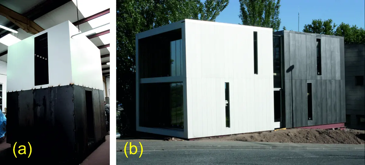
The COTaCERO research project was developed in 2012. It consisted of building the roof slab at ground level, lifting it by means of jacks to its final position, and building the upper floor also at ground level. In this case, the resistant element was the perimeter panels of sheet steel welded together. Once the upper floor was built, it was raised again by means of jacks and the next floor was built, joining the beams and slabs by welding to the resistant panels (Figure 1a). Continuing the process, several floors could be built, the number of which was limited simply by the performance of the panels. During the development of the works, these were always carried out at ground level, which improved the conditions of the workers both in terms of safety and ease of work[10,12-14].
The Reverstop® research project was developed in 2014 and 2015. It starts from the same principles, but with major modifications that represent important improvements, which will be analyzed in this article. As in the previous case, the building is built at ground level with a structure formed by light metal sheet panels, and the different floors of the construction are raised as they are completed by means of hydraulic jacks. In the case studied, an experimental module was built in which one part was built with extruded aluminum profiles and another part with folded steel sheets. In both cases bolted joints were used, which required a detailed study of the joints and linkages. Its resistant behavior was analyzed considering that they are thin and very slender sections that correspond to class 4 according to Eurocode EC-3[15]. It is a topic that has been the subject of numerous studies, among which we can cite[10,16-21]. In this specific case, theoretical and experimental analyzes were carried out that have been described in a previous article[22].
The Reverstop® system itself is an original patented system. It has been described in the publication cited above, but this article develops important aspects for its design and execution that have not been addressed before.
The originality of the article focuses on the following issues:
• Detailed analysis of the lifting systems and especially the one used in the construction of the modules. Also of the necessary auxiliary elements.
• Analysis and experimental verification of the support joints of the panels, which are an essential element in the design of the system.
2. Reverstop® System Description
The basic concept of the proposed solution of the Reverstop® system is a building with thin perimeter load-bearing panels, but bolted together, which is a significant improvement over the COTaCERO welded system, in which welded joints represented a notable increase in cost (Figure 1b). In the Reverstop® system, the panels transmit their load at each level to a perimeter beam for simple support. This requires the design of elastic joints that allow this transmission of loads, which is one of the objectives of this article. The joist that supports the floor, formed by wooden sandwich panels with the appropriate level of insulation, are also supported on this perimeter beam.
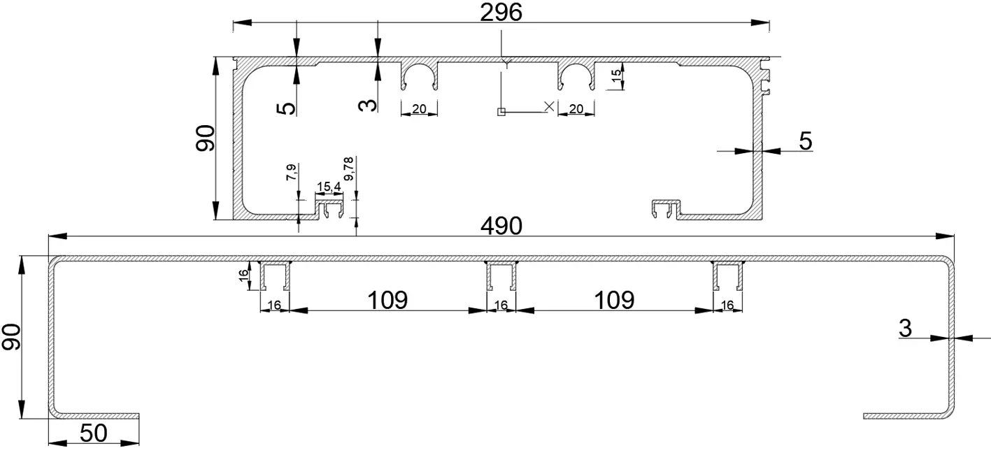
The main element is the metal panel that has been designed with special care. Two different types of modules have been built with 296 × 90 mm aluminum panels and 490 × 90 mm steel panels in order to analyze their advantages and disadvantages (Figure 2). The aluminum profile could not exceed these measurements, since it was limited by the maximum dimensions of the extrusion nozzle available. The steel profile did not have this limitation, so it adopted a greater width.
The aluminum panel required a special study to design a piece with a unique profile that could work as a resistant façade element against vertical loads (Figure 3a), as a joist to support the floor (Figure 3b) and as a roof element (Figure 3c), with the maximum span possible. The objective was to be able to use a single extrusion nozzle, given its high cost. The profile has two internal projections that serve to limit buckling and also to support some polyvinyl chloride (PVC) tubes that are used for thermal conditioning of the module, which was the subject of a separate study.
In the case of the steel panels, they were made with bent sheet metal to which three small U-shaped profiles were welded to limit buckling and place the cooling tubes. This same profile was placed as a roof element, but IPE profiles were used for the joists, which are more common and cheaper.
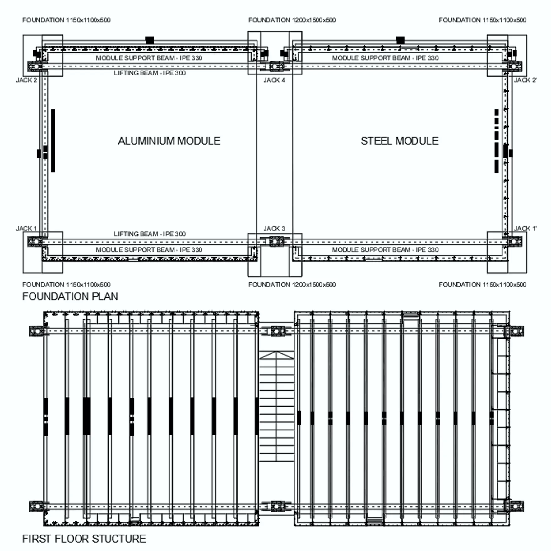
To analyze the feasibility and effectiveness of the system, the Reverstop® research project was carried out between February 2014 and June 2015. As a result, an experimental module was built on the A Zapateira Campus of the University of A Coruña. It consisted of two modules, one made of aluminum and the other made of steel, each measuring 6x6 m in plan and with two floors 3 m high, which were linked by an access corridor of 1.20 m. In this corridor the access staircase was placed and on it some solar panels to provide the necessary energy for the different measurement elements. Both modules were built from ground level and then raised by means of hydraulic jacks[22]. Once the project objectives were met, the module was dismantled in March 2016.
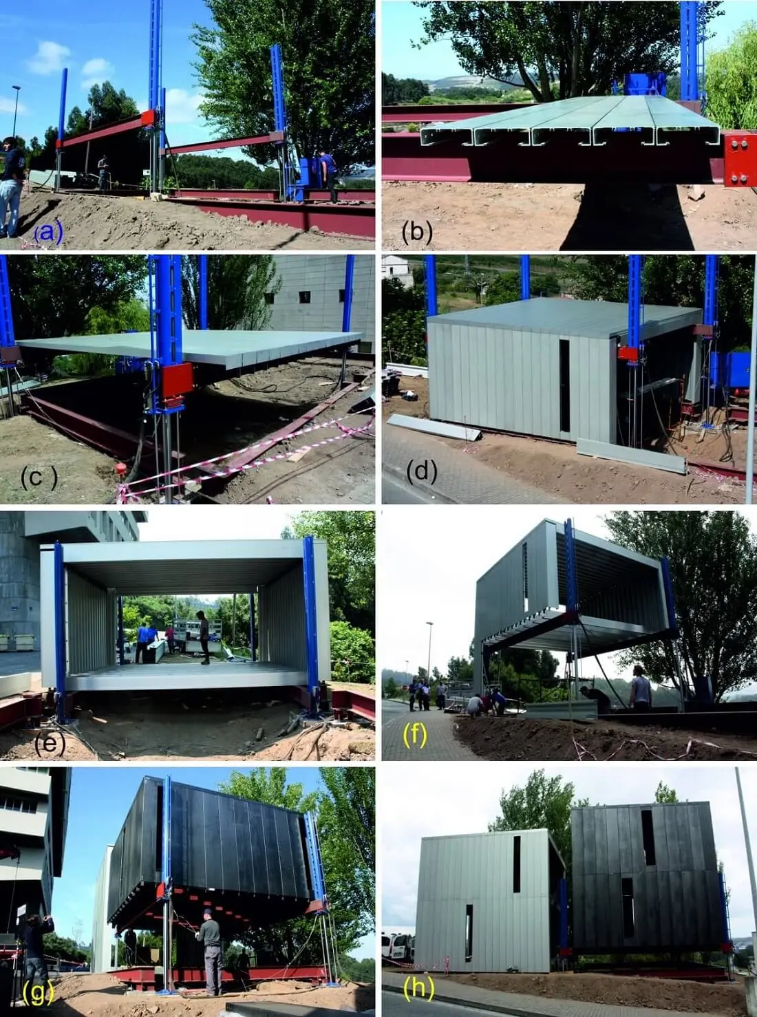
The construction process was the one indicated in Figure 4.
a. On a previously built foundation, the profiles were placed on the ground to support the cover. The jacks descend to later raise the roof built at ground level.
b. The roof was built at ground level. In this case, the roof was formed by aluminum profiles screwed together and with an elastic joint to prevent the entry of water.
c. The built roof was raised by means of jacks to allow the construction of the walls of the upper floor.
d. The enclosures of the upper part were also built at ground level on the lateral profiles that served as support for the upper floor slab.
e. The joists of the slab were placed on the lateral profiles.
f. The upper floor, already built, was raised to its final position. The lower floor was then built using the same technique.
g. Once the aluminum module was built, the process was repeated with the steel module. In this case, the hoisting of the upper floor is shown, carried out with the same techniques as in the aluminum module.
h. Once the complete building was finished, one of the modules was raised to verify that it would have been possible to add a new floor with the dimensions of the profiles and panels used. The steel module was chosen because it is the heaviest and the result was completely positive.
Initially, a distribution like the one indicated in Figure 5 was planned, but due to budgetary limitations and because it is an experimental module, only the exterior enclosures have been built with the large window in the aluminum module, the staircase and a set of solar panels, above the staircase to provide power supply to the measuring devices to carry out a series of tests.
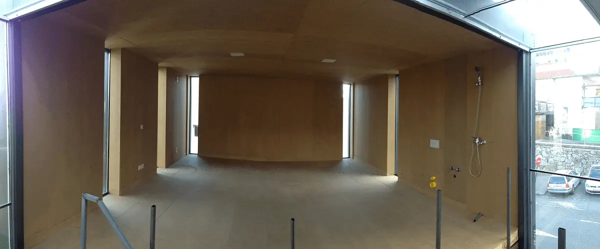
The enclosures are made up of an exterior facade of resistant metal panels that constitute the load-bearing structure and at the same time are the exterior sheet of some ventilated facades. The inner sheet is made up of wooden panels with internal rock wool insulation. A series of PVC pipes that contain water and that allow the thermal conditioning of the interior are placed on the metal panels[23]. Various interior enclosure panels designed to contain the mechanisms and connection elements to the electrical, plumbing or telecommunications installations have been placed (Figure 6). The finished interior appearance is shown in Figure 7.
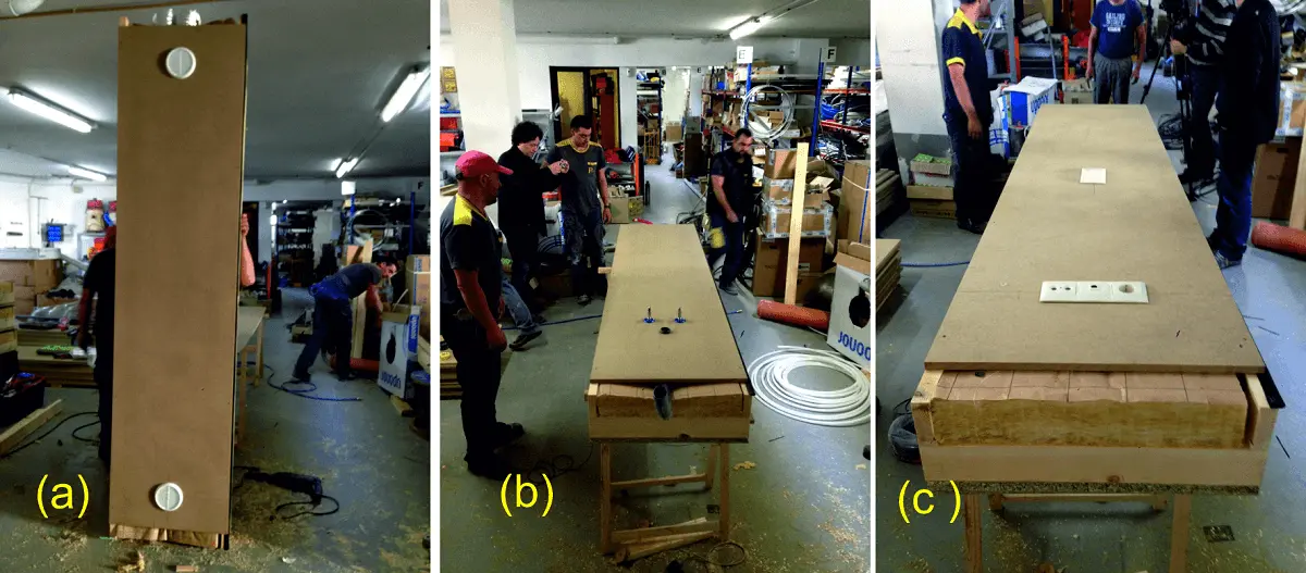
Figure 6. Interior enclosure panels with ventilation (a), plumbing (b) and electrical mechanisms (c).
3. Hoisting Systems
The hoisting system is based on the use of hydraulic jacks that lift the supporting structure formed by the perimeter panels from the outside. This means that during the work the upper floors will only be supported by the jacks and exposed to the action of the wind. It is necessary to design stiffening systems that guarantee the safety of the building at this particularly critical moment. For this, our team has studied various stiffening systems:
• Embedding of hydraulic jacks in the foundation.
• Extendable cables with safety lock.
• Telescopic bars with progressive locking.
• Auxiliary structures
Choosing the most suitable system depends on the characteristics of the building and the foreseeable wind intensity.
3.1 Construction on jacks embedded in the foundation
In this case, the jacks are simply embedded in the foundation, which must therefore be sufficient to resist the horizontal forces in the most unfavorable position. This means that the action of the wind causes greater efforts as the building is raised and could require unnecessarily large foundations. It is a system that is only viable in low-rise and small-sized buildings, and even in that case it is advisable to use an auxiliary emergency system.
3.2 Bracing with tensile cables with safety lock
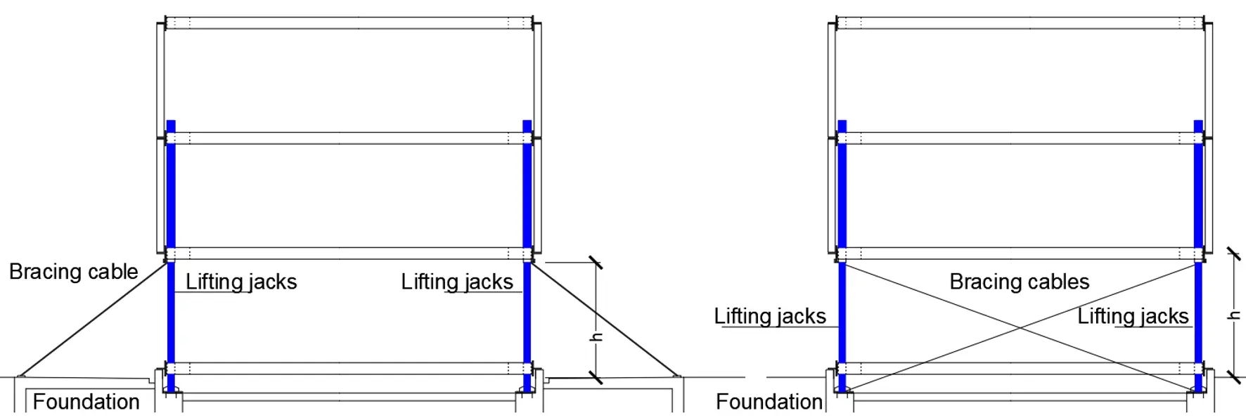
The heads of the hydraulic jacks are held by cables of limited extension and with a safety lock that fixes them in the intermediate positions in the event of a possible accidental action. The main problem with this system is that the cables must allow the resistant façade panels to be installed before being removed. The set of cables and jacks must resist 100% of the horizontal forces in the raised position and in all intermediate positions. When conditions allow, the cables can be fixed to the existing foundation (Figure 8).
3.3 Bracing with telescopic diagonal bars with progressive locking system
The system is similar to the previous one, but using telescopic diagonal bars as a locking system. It has the advantage over the cable system that this type of bracing can work under compression (Figure 9).
3.4 Auxiliary structures for bracing
An interesting solution for large-scale works is the construction of a provisional structure that allows the building to be supported during hoisting and at the same time can serve as a warehouse or protection for the operators. These structures must have a slip joint that allows the panels to be raised with the jacking system. The auxiliary structure must have a sufficient resistant capacity to resist the horizontal forces caused by the wind and possible accidental actions (Figure 10).
For this, three-dimensional cell-type elements can be used, prefabricated, transported to the site and assembled, like normal work modules. They must be placed parallel to the load-bearing façade and be correctly secured to the foundation to guarantee their stability.
3.4 Hoisting system used in the prototype
In this specific case, the modules built have used the system of jacks braced with cables, although it was not considered necessary for them to have locking retainers. Four hydraulic jacks were used first to lift the aluminum module and then two of them moved to build the steel module (Figure 11). As a reference, a wind speed of 28 m/s = 100.8 km/h was considered, but the maximum acceptable speed for hoisting was limited to 40 km/h. During construction, this speed was never exceeded, but gusts of this magnitude occurred during its useful life without the structure suffering any type of damage.
The jacks used are MDI Ø125/Ø90 x 3000 BD type manufactured by Mecanohidráulica Escenarios S.L. with system load capacity of up to 400 kN. The maximum load to be raised does not exceed 100 kN, so its resistance is sufficient.
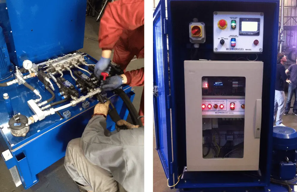
To achieve a correct leveling of the jacks, a hydraulic regulation system was used by means of a flow divider. The amount of hydraulic fluid in each cylinder was the same, regardless of its load, which meant a synchronized displacement of the cylinders fed by the divider. Better accuracy was achieved in exchange for less speed, which is not critical. The speeds were 0.01 m/s in ascent and 0.02 m/s in descent. The maximum leveling error was 2 mm, which was controlled in all phases of the process (Figure 12).
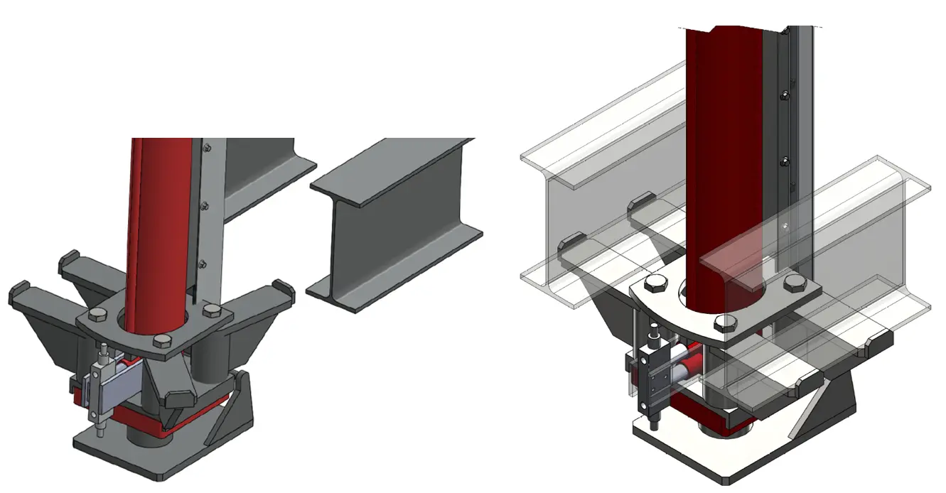
The jacks (in red) were attached to a system of articulated claws on which the lifting beams were supported (Figure 13).
Since the loads transmitted by the hoisted modules were low, an auxiliary system of diagonal bracing cables was placed, which were stabilized in the final position. It was not considered necessary to place retainers, since the wind speed was limited during the hoisting maneuver to values that did not imply risk (Figure 14).

Figure 14. Positioning of the jacks and lifting of the aluminum module with the bracing cables.
4. The Joint Problem
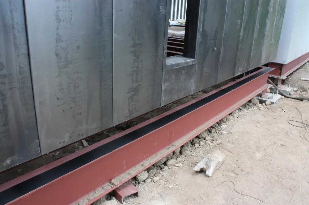
The main problem posed by the REVERSOP system is the transmission of vertical loads through the façade panels. The direct transmission through the screws is only effective for heights up to two floors. In the initial project, the module had been designed with a resistant capacity of up to five floors, but budgetary limitations forced it to be reduced to two. For heights greater than these two, the necessary construction looseness would cause excessive tension in screws, since the building loads would be transmitted almost exclusively to them. The solution adopted consisted in having the panels rest on an edge beam. In turn, this beam transmits its load by compression to the lower panels. Since it is not possible to achieve perfect flatness in the contact surfaces, it is necessary to place an intermediate elastic joint (Figure 15).
The performances that a correct joint material must satisfy are:
• It must allow enough plastic deformations to absorb the irregularities of the panels.
• It must not break under applied stresses.
• It must have a stabilized long-term deformation.
• In addition, it must meet the thermal insulation conditions required for the entire building. It would not be acceptable for the joint to be a thermal bridge.
The facade panels are the resistant elements of the structure. For this reason, they are subject to high stresses. No joint material can resist these efforts in the elastic phase: it is a matter of being able to resist these efforts, even with large deformations, but without actually breaking. It is necessary to test elastic joints, both in the short and long term, to check the deformation conditions. This article will describe the studies carried out to select the most appropriate one.
5. Description of Materials and Test Techniques
The aluminum alloy used for the extrusion of the analyzed profiles is Al Mg Si alloy 6082, with an elastic modulus of 69,000 MPa and an elastic limit of 250 MPa. The steel is S 275 JR in 3 mm sheet, with an elastic modulus of 210,000 MPa and an elastic limit of 275 MPa. For the execution of the tests, the same profiles used in the building were used.
Three types of tests have been carried out. First, a 1:1 scale joint model was tested to observe its general behavior and, in particular, to specify the problems of the initial joint and the buckling of the assembly. Based on the results obtained, various joint materials were tested in the short term and once the most suitable material was selected, said material was tested in the long term.
5.1 Previous test
Firstly, a test was carried out with a full-scale model of the linkage. The joint was made up of two 5 mm thick steel half panels with a contact area of 3,706.58 mm2. The joint consisted of a 2 mm sheet of Ethylene Propylene Diene Monomer (EPDM, M-class) rubber).
The test was carried out in an INSTROM universal testing machine with a capacity for 1,000 kN from the Center for Technological Innovation in Building and Civil Engineering of the University of A Coruña. The test was carried out with a load increment of 1 kN/s (0.75mm/min).
The model was tested until failure, which was produced by local buckling. The applied load reached 595 kN, which means a tension transmitted to the panels of 160.52 MPa. This implies that the limitation of the Reverstop® system is defined by the buckling conditions. Since this test made it possible to verify that the resistance of the joint was much higher than necessary, it was decided to use 3 mm thick panels in the module built.
Figure 16 shows the collapsed linkage after the test and the FE calculation model used in the theoretical verification.
When analyzing the tested linkage, it was possible to verify that the EPDM joint placed was completely broken. For this reason, it was decided to proceed with a systematic investigation of the possible materials, in order to use the most appropriate one. These tests are presented in Section 5.2.
Since budget limitations forced the initial project to be reduced to two floors, the possibility of transmitting the vertical forces between panels by means of bolted joints to a vertical plate to which the joists were fixed was also analyzed. To verify the effectiveness of this system, a new test was carried out using the same type of machine described in the previous section.
The test made it possible to verify the effectiveness of the joints up to an applied load of 70 kN, much higher than that estimated on the joint, which was 23.5 kN. For the applied load, traces of the screw thread were produced on the aluminum sheet, which indicates that plasticization occurs, although it hardly influences the resistant capacity of the joint (Figure 17).
5.2 Short-term tests of the joints
The selected materials were High-density polyethylene (HDPE), neoprene, EPDM, rubber reinforced with steel fibers (RNR) and PVC reinforced with fiberglass. The mechanical characteristics of the selected materials are as follows.
Table 1 shows that only in the case of HDPE can a reasonably elastic behavior be accepted. The rest of the materials deform plastically, even at low stresses, so we cannot define precise mechanical characteristics, except for the breaking stress.
| Joint Material | HD-PE | Neoprene | EPDM | RNR | PVC |
| Density (g/cm3) characteristic values | 0.95 | 1.46 | 1.31 | 1.60 | 0.92 |
| Yield Strength (N/mm2) characteristic values | 23 | - | - | - | - |
| Tensile strength (N/mm2) characteristic values | 37 | 9 | 7 | 4 | 50 |
| Elastic Modulus (N/mm2) characteristic values | 800 | - | - | - | - |
| Percent Elongation (%) characteristic values | > 50 | 250 | 300 | 200 | > 70 |
EPDM: Ethylene Propylene Diene Monomer; RNR: rubber reinforced with steel fibers; PVC: polyvinyl chloride; HDPE: high-density polyethylene.
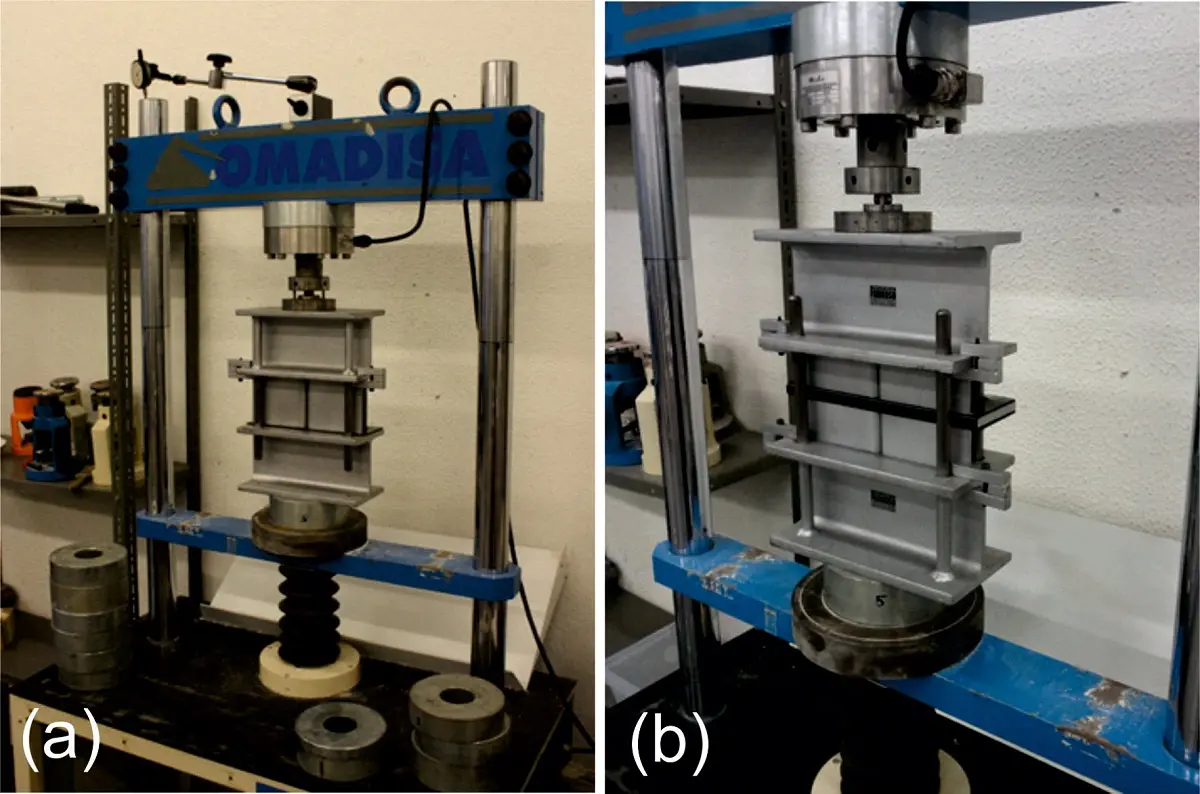
To test the joints in conditions similar to those of the final building, a specific assay bench was designed for this test. Figure 18 shows the characteristics of the assembly. Simple joints were tested for the extreme sections of the panels and double joints for the intermediate sections.
The tests were carried out in the laboratory of the School of Technical Architecture of A Coruña, using an Omadisa 120-31 compression testing machine with a Microtest PBI/20 load cell with high-precision digital control. Supports a maximum load of 200 kN. The tests were carried out for a design maximum stress of approximately 100 MPa which is more than double that expected in the actual building, which was 42.53 MPa in the worst case. This meant that the maximum load to be applied in the test was 185 kN. With these tests it was intended to have data to increase the number of plants or decrease the thickness of the panel.
The loading for these tests was at a speed of 200 N/s until reaching the set load. The sampling interval was 1 second, and the number of readings per test was in the order of a thousand.
The plan view of the load profiles is the one indicated in Figure 19. Each L-shaped profile supposes a distribution area of 927 mm2, so the total load of 185 kN will be applied on 1,854 mm2, which represents a maximum load stress of 99.78 MPa.
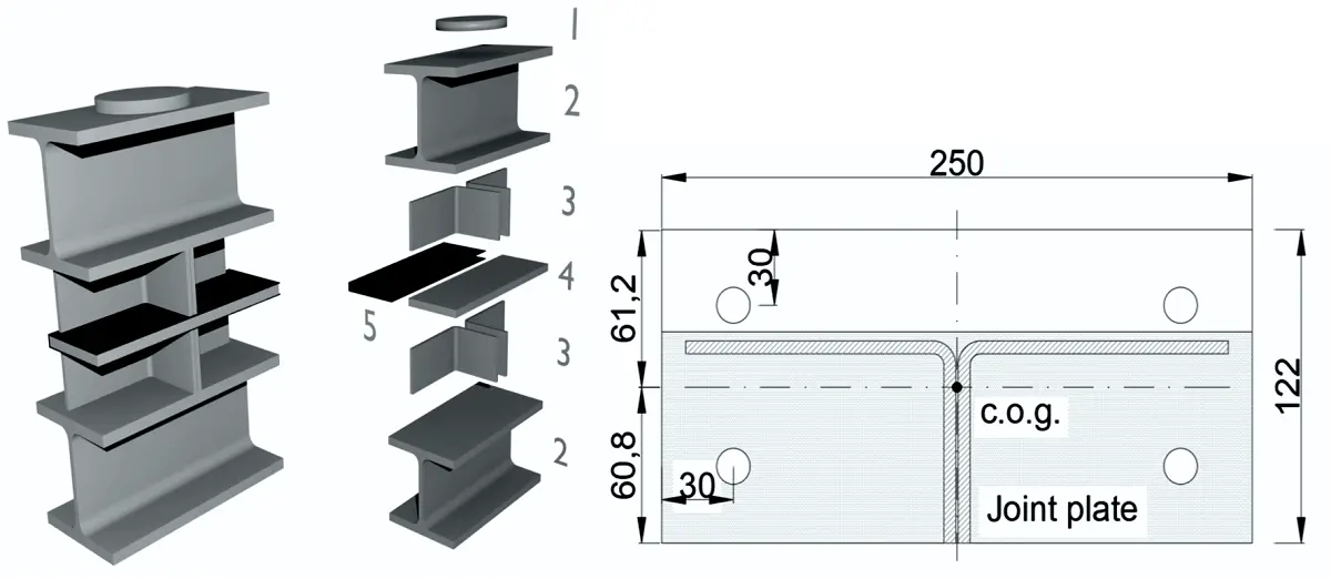
Figure 19. Scheme of short-term tests and diagram of the support of the profiles on the joint (5).
5.3 Long term tests
The long-term tests are carried out in a fixed press with the scheme of Figure 20 and a load of 70 kp formed by 7 gym weights of 10 kp each. 6 tests of 1 mm high-density polyethylene samples and another 6 samples of 2 mm thickness were carried out. Since the results of the short-term tests in which the only valid material was HDPE, these tests were built only with this material.
The test press had a support arm formed by a rectangular tube 60.20.1.5 with a total weight of 2.17 kp. The support pivot for the weights was a Ø25 tube with a weight of 0.285 kp, so the total reaction transmitted to the HDPE specimen was 7,235.9 N. Since the load surface was 40 × 5 mm, the total tension transmitted to the tested specimen was 31.18 N/mm2, higher than the stress transmitted by the profiles to the joint in the actual building.
6. Test Results
6.1 Short-term tests of joints
First, a series of six tests was carried out for each of the materials. In this first series, the joint sample was placed on the lower profile, a set of two steel half panels was placed on it, and the load was applied through an upper profile. The load application point was made to coincide with the center of mass of the set of both half panels.
The test machine provided the transmitted load and measured displacement data. It is necessary to correct the displacement results, because elastic shortening of the test bench also occurs. To do this, a set of six tests without an elastic joint was carried out. The loads were transmitted directly through the steel panels and thus the displacement of the test assembly could be measured without considering the effect of the joint. The results were very consistent, so this value could be subtracted from that measured in the test results to directly obtain the displacements of the joint material.
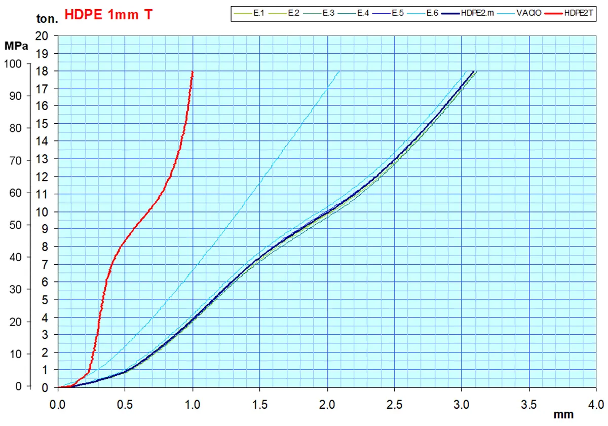
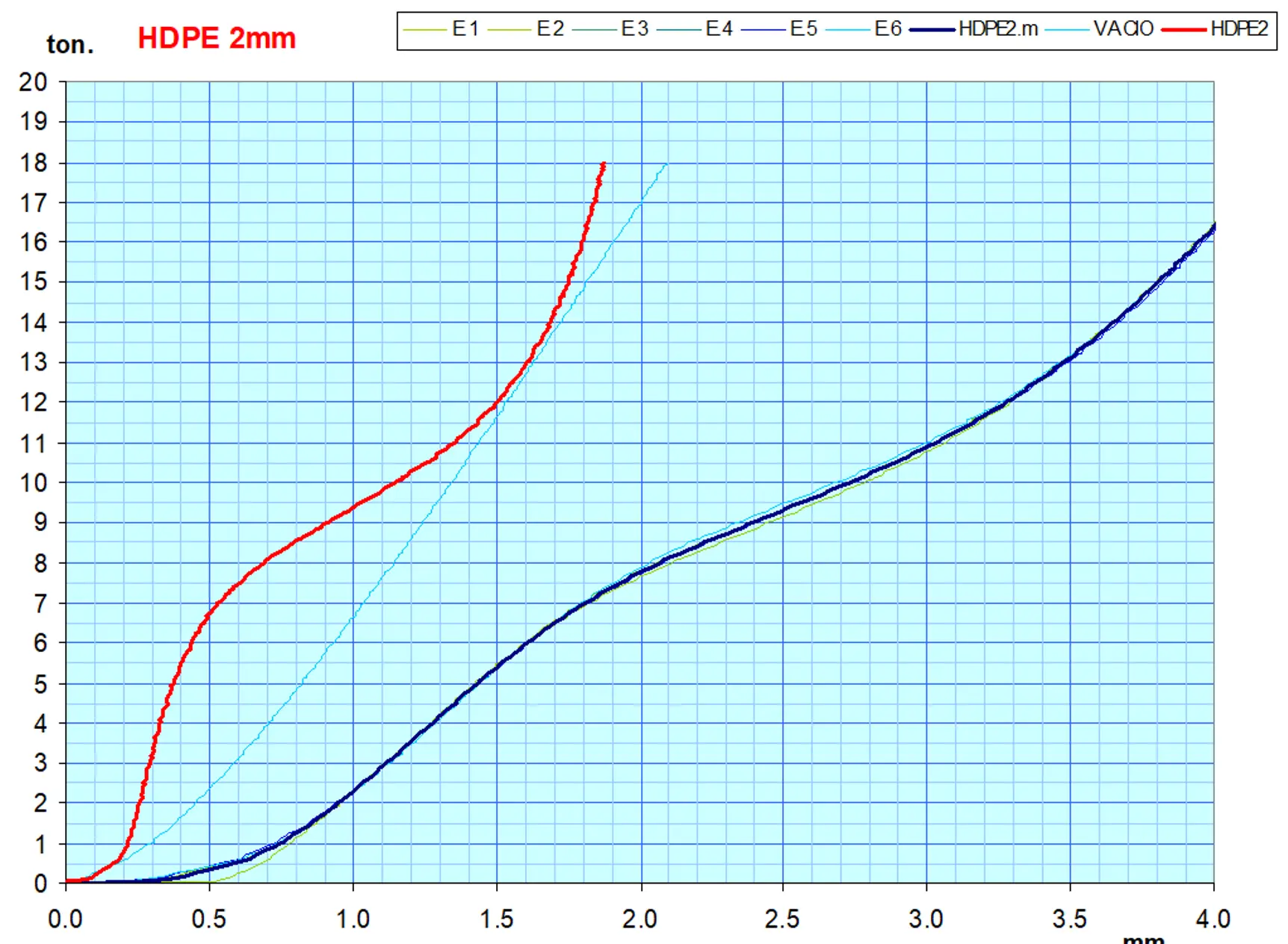
Figure 21 shows the graphs of tests on neoprene, EPDM, RNR, and PVC gaskets, which gave unsatisfactory results. In all of them, the overall results of the tests are indicated in green and their mean value in dark blue. In light blue the deformation of the test set without elastic joints is indicated and in red the corrected result with said test is shown, to allow its correct evaluation.
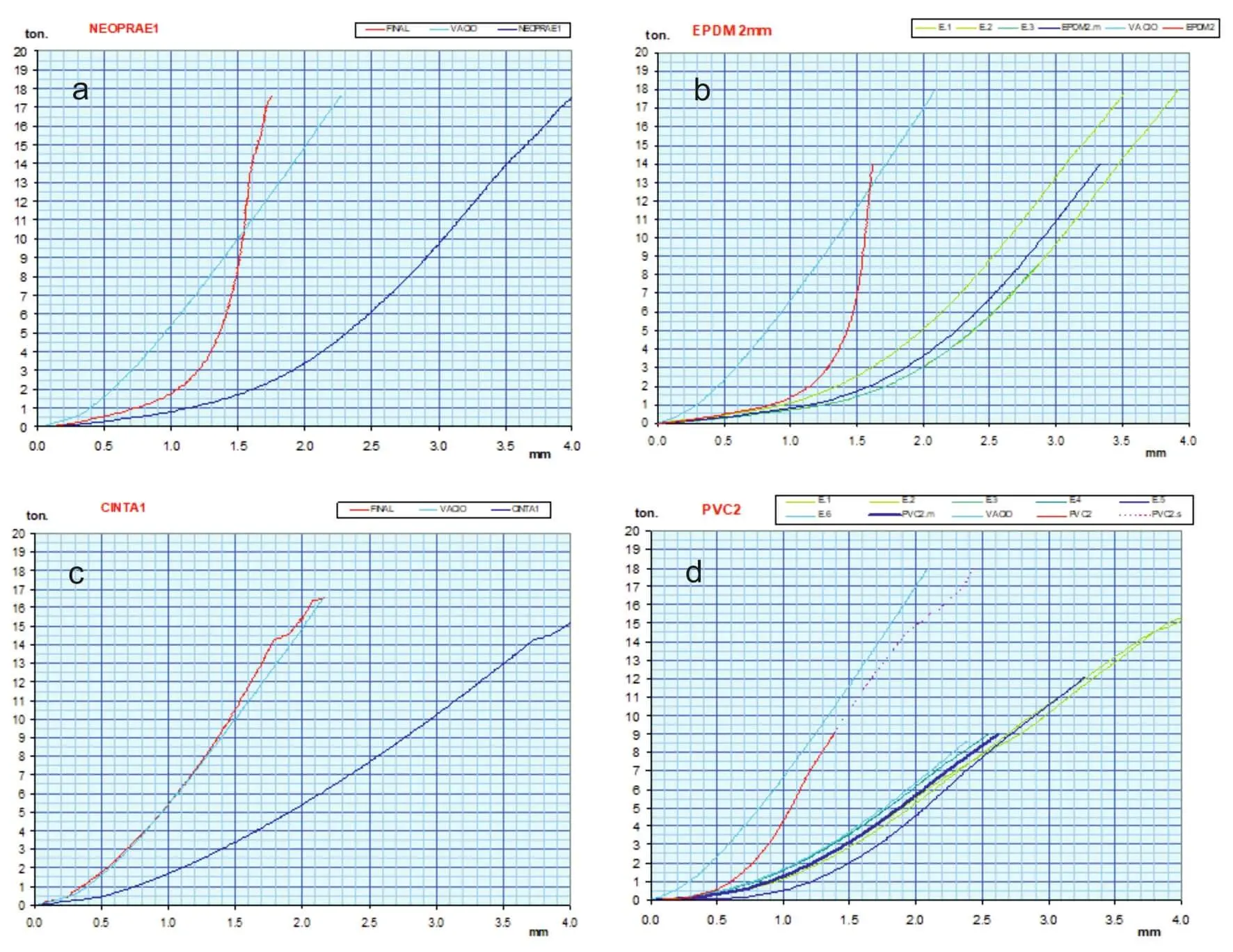
Figure 21. Tests on failed materials showing (a) Neoprene; (b) EPDM; (c) RNR; (d) PVC. EPDM: Ethylene Propylene Diene Monomer; RNR: rubber reinforced with steel fibers; PVC: polyvinyl chloride.
These first series of tests made it possible to verify that the only material capable of resisting the total load applied without breaking was HDPE. However, there was a question as to what its behavior could be in the real conditions of the building. For this reason, a new series of tests was programmed, which this time concentrated on HDPE joints, since the others had already been discarded.
Although previous tests had shown that the use of greater joint thicknesses did not imply an improvement, new tests were carried out with 1 mm and 2 mm joints. The objective was to test the joints in conditions equivalent to those of the real building. The results of the second series of tests were those indicated in Figure 22 and Figure 23, expressed with the same color criteria.
6.2 Long-term tests of HDPE joints
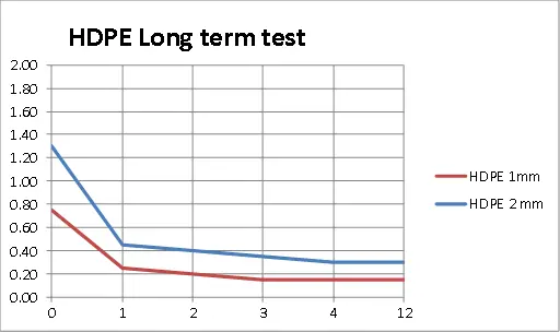
The development of the experiment consisted of placing an HDPE specimen that was subjected to a rapid test and subsequently the thickness of the crushed sample was measured with a METRICA 43180 caliper with a precision of 0.05 mm. Next, a new sample was placed, which was withdrawn after a week, measuring its thickness. The process was always repeated with new specimens, in all HDPE cases, at 2, 3, 4 and 12 weeks. One millimeter and two millimeter samples were tested with the results shown in Table 2.
| Load duration in weeks | 0 | 1 | 2 | 3 | 4 | 12 |
| Final thickness measured (1 mm) | 0.75 | 0.25 | 0.20 | 0.15 | 0.15 | 0.15 |
| Final thickness measured (2 mm) | 1.30 | 0.45 | 0.40 | 0.35 | 0.30 | 0.30 |
As can be seen after four weeks, the thickness of the sample remains constant, being 15% of the initial thickness regardless of the thickness of the sample (Figure 24).
7. Discussion
In this article, two of the main problems of the Reverstop® system have been analyzed in a special way, such as the lifting systems and the elements of the joints. Theoretical calculations had shown that the system can be used under normal conditions for buildings of up to five floors, but the main utility of the system is in constructions of two or three heights and with spans of about six meters. For this type of construction, the most appropriate lifting system is that of jacks embedded in the foundation, braced with cables. For hoisting it is essential to ensure the correct leveling of the jacks, which has been achieved with the hydraulic regulation system using a flow divider described in Section 3.5. It is also important to correctly brace the assembly during the lifting process, which is the most unfavorable position for the jacks. With the dimensions and heights analyzed, a bracing system with cables has been chosen, which has proven its effectiveness. However, it is important to limit the hoisting process to favorable weather conditions with wind speeds of less than 40 km/h.
As for the joint materials, a complete study of them has been carried out, analyzing the five most used. The only material that effectively withstood the tests was HDPE, which was subjected to new short- and long-term tests that confirmed its effectiveness. This material was capable of resisting the stresses applied with strong plastic deformations, but never breaking. In the case of long-term tests, a very strong instantaneous deformation has been observed, but this deformation stabilizes over time and after one month the thickness of the sample remains fixed at 15% of the initial thickness.
The construction system tested with Reverstop® has been developed by the company Proyectopia, which has focused on aluminum panels. In this case, as they are light and low-rise houses, they have been built without hoisting with the Walluminium system, which in its construction aspects is similar to Reverstop® (Figure 25)[1].
8. Conclusions
The developed project has allowed to demonstrate the effectiveness of the Reverstop® system. The complete construction of the modules has been able to be carried out at ground level, raising the successive floors of the building as they were being completed. This has been possible with a simple and cheap jacking system, using a leveling system that has been shown to be highly effective.
The resistant element is formed by the façade panels that fulfill a double function. In the built prototype, aluminum and steel panels were used to be able to contrast their performance. It has been possible to verify a better performance of the aluminum panels, which are the ones that have been used in this project and in subsequent realizations.
A critical element and with few previous studies are the elastic joints. The only option of all the materials tested was HPDE which, despite not being designed for these purposes, has exceptional mechanical behavior. The calculations carried out show that, with the expected spans and loads, up to 6 floors could work well, in the absence of more specific materials for this purpose.
The results of this research have been developed in different buildings made with the Walluminium system, which uses the same structural and joint elements analyzed in the Revestop project. This has allowed the joints studied to be validated in a practical way.
Acknowledgments
The authors wish to thank the collaboration of Instalaciones Parcero S.L.U., ALUTEC and Talleres Formoso in carrying out this project.
Authors contribution
All authors contributed equally to this work.
Conflicts of interest
The authors declare no conflicts of interest.
Ethical approval
Not applicable.
Consent to participate
Not applicable.
Consent for publication
Not applicable.
Availability of data and materials
Not applicable.
Funding
The article was supported by a grant from XUNTA DE GALICIA through the research project Conecta-Peme Program of the Xunta de Galicia (27-6-2014) with reference IN852A 2014/12.
Copyright
© The Author(s) 2024.
References
-
1. Vanderklaauw PM, inventor; Research Corp, assignee. Method of erecting a multi-story building and aparatus therefor. US Patent 3831902. 1974 Aug 13.
-
2. Feld J, Carper KL. Construction Failure. 2nd ed. New York: John Wiley & Sons. 1997. p. 311-315.
-
3. Masih R. Stability of lift slab structure during construction stage. In: Proceedings of the Structures Congress ‘94 Atlanta; 1994 Apr 24-28; Atlanta, USA. Virginia: ASCE; 1994. p. 271-277., Available from: http://cedb.asce.org/CEDBsearch/record.jsp?dockey=0086682.
-
4. Zallen RM, Peraza DB. Engineering considerations for lift-slab construction. Virginia: ASCE (American Society of Civil Engineers); 2003.[DOI]
-
5. Porter JB. Lift-slab construction: its implications in building design and engineering. American: Building Research Institute, Division of Engineering and Industrial Research, National Academy of Sciences, National Research Council, 1955. Available from: https://books.google.com/books?id=aUsrAAAAYAAJ
-
6. Riusillo MA. Lift slab construction: its history, methodology, economics, and applications. Int Concr Abstr Portal. 1988;107:59-68.[DOI]
-
7. Gaidukov PV, Pugach Evgeny EM. Technological aspects of lift-slab method in high-rise-building construction. E3S Web Conf. 2018;33:02068.[DOI]
-
8. Martínez Calzón J, Asensio Marchante J. Elevación de la cubierta del Palau Sant Jordi. Madrid: Revista de Obras Públicas. December 1998. p. 1099-1109. Spanish.
-
9. Colbert B. Procedimiento y dispositivo de realización semiautomática in situ, de depósitos metálicos. Spanish Patent 2228855. 2001.
-
10. Hermo Sánchez VM. Sistema constructivo industrializado in situ COTaCERO: transferencia tecnológica: construcción de depósitos-ejecución de viviendas en altura mediante paneles portantes de acero [dissertation]. Spain: University of A Coruña; 2011. Spanish. Available from: https://www.academia.edu/105785376/Sistema_constructivo_industrializado_in_situ_COTaCERO_transferencia_tecnol%C3%B3gica_construcci%C3%B3n_de_dep%C3%B3sitos_ejecuci%C3%B3n_de_viviendas_en_altura_mediante_paneles_portantes_de_acero
-
11. Programa Conecta-Peme de la Xunta de Galicia. Research and development of a new construction system of reversible modular growth from the ground level with energy efficiency criteria. 2014. Galician.
-
12. Rodríguez Cheda JB, Pérez-Valcárcel JB, HERMO SÁNCHEZ VM, inventor; Universidade da Coruna, assignee.Método para construir edificaciones de varias plantas mediante paneles portantes ligeros desde el nivel del terreno. Spanish Patent 2370438. 2012 Oct 22.
-
13. Valcárcel JP, Hermo V, Rodríguez Cheda JB. A New Building System: Structural Aspects of CotaCero System. In: Paulo J. Cruz,editor. Structures and Architecture: New concepts, applications and challenges. London: CRC Press; 2013. p. 1056-1063. Available from: https://www.academia.edu/69419239/A_new_building_system_Structural_aspects_of_COTaCERO_system
-
14. Valcárcel JP, Hermo V, Rodríguez Cheda JB. Structural Behaviour of CotaCero System during the Lifting Process. In: Proceedings of the International Conference Transformables; 2013 Sep 18-20; Seville, Spain. 2013. p. 169-174. Available from: https://www.researchgate.net/publication/364716349_Structural_behaviour_of_COTaCERO_system_during_the_lifting_process
-
15. EN 1993-1-1 (2005): Eurocode 3: Design of steel structures [Internet]. The European Union Per Regulation 305/2011, Directive 98/34/EC, Directive 2004/18/EC; 2005 [cited 2024 Jan 16]. Available from: https://www.phd.eng.br/wp-content/uploads/2015/12/en.1993.1.1.2005.pdf
-
16. Davies JM. Recent research advances in cold - formed steel structures. J Constr Steel Res. 2000;55(1-3):267-288.[DOI]
-
17. Davies JM. Developments in stressed skin design. Thin-Walled Struct. 2006;44(12):1250-1260.[DOI]
-
18. York CB, Pedreschi R. The influence of geometry on the strength of shear wall panels on light steel construction. Constr Build Mater. 2000;14(5):277-285.[DOI]
-
19. Davies JM, Fragos AS. The local shear buckling of thin-walled cassettes infilled by rigid insulation. J Constr Steel Res. 2004;60(3-5):581-599.[DOI]
-
20. Veljkovic M, Johansson B. Light steel framing for residential buildings. Thin-Walled Struct. 2006;44(12):1272-1279.[DOI]
-
21. Craveiro HD, Rodrigues JPC, Laím L. Buckling resistance of axially loaded cold-formed steel columns. Thin-Walled Struct. 2016;106:358-375.[DOI]
-
22. Pérez-Valcárcel J, Muñoz-Vidal M, Hermo V. Construcción izada: Condicionantes estructurales del sistema REVERSTOP®. Informes de la Construcción, 2020;72(559): 355. Spanish.[DOI]
-
23. Antelo Tudela E. Las instalaciones como condicionante del diseño arquitectónico: panel técnico Reverstop [dissertation]. Spain: University of A Coruña;2016. Spanish. Available from: https://core.ac.uk/reader/61919244
Copyright
© The Author(s) 2024. This is an Open Access article licensed under a Creative Commons Attribution 4.0 International License (https://creativecommons.org/licenses/by/4.0/), which permits unrestricted use, sharing, adaptation, distribution and reproduction in any medium or format, for any purpose, even commercially, as long as you give appropriate credit to the original author(s) and the source, provide a link to the Creative Commons license, and indicate if changes were made.
Publisher’s Note
Share And Cite


