Novel non-diffracting beams engineered via localized spatial frequency mapping
*Correspondence to:
Peng Li, Key Laboratory of Light Field Manipulation and Information Acquisition, Ministry of Industry and Information Technology, and Shaanxi Key Laboratory of Optical Information Technology, School of Physical Science and Technology, Northwestern Polytechnical University, Xi’an 710129, Shaanxi, China.
E-mail: pengli@nwpu.edu.cn
Sheng Liu, Key Laboratory of Light Field Manipulation and Information Acquisition, Ministry of Industry and Information Technology, and Shaanxi Key Laboratory of Optical Information Technology, School of Physical Science and Technology, Northwestern Polytechnical University, Xi’an 710129, Shaanxi, China. E-mail: shengliu@nwpu.edu.cn
Sheng Liu, Key Laboratory of Light Field Manipulation and Information Acquisition, Ministry of Industry and Information Technology, and Shaanxi Key Laboratory of Optical Information Technology, School of Physical Science and Technology, Northwestern Polytechnical University, Xi’an 710129, Shaanxi, China. E-mail: shengliu@nwpu.edu.cn
Light Manip Appl. 2026;1:202505. 10.70401/lma.2026.0008
Received: December 05, 2025Accepted: March 26, 2026Published: March 27, 2026
Abstract
Non-diffracting beams are typically confined to a limited set of specific profiles. Existing methods for diversifying these beams face challenges in achieving arbitrarily complex intensity distributions. In this paper, we present a phase engineering approach based on local spatial frequency mapping to construct novel non-diffracting beams. The proposed method facilitates the creation of customized intensity profiles by tailoring and splicing phase modulations in the Fourier domain, enabling the generation of intricate non-diffracting beams, such as those with a Tai Chi shape. We experimentally demonstrate the robust propagation invariance and self-healing capabilities of these novel non-diffracting beams. This approach provides a versatile means for designing structured non-diffracting fields, with potential applications in areas such as precision laser machining, optical trapping, free-space communication, and structured-light imaging.
Keywords
Non-diffracting beams, light manipulation, local spatial frequency mapping, spatial spectrum engineering, intensity shaping
1. Introduction
Non-diffracting beams, also known as propagation-invariant beams, refer to special optical fields maintaining invariant transverse intensity distributions during propagation. In 1987, Durnin[1] first theoretically proposed non-diffracting Bessel beams as a particular solution to the free-space scalar wave equation, characterized by a transverse distribution described by a first-order Bessel function. Subsequent works have expanded this concept by solving the Helmholtz equation in different coordinate systems, yielding additional types of non-diffracting beams such as Mathieu beams[2,3], Weber beams[4,5], and Airy beams[6]. These beams exhibit unique propagation properties, including non-diffraction and self-healing during propagation[7,8], self-bending and transverse acceleration[6,9,10]. By leveraging these properties, researchers have designed and realized a variety of structured optical fields with tailored functionalities[11-18]. As a result, such beams have been extensively studied and widely applied in laser processing[19-21], optical micromanipulation[22-25], optical communication[26-29], and optical imaging[30-34]. However, the transverse intensity distributions of the aforementioned beams are primarily based on predetermined functional forms, inherently limiting their diversity.
Therefore, numerous research groups have proposed methods to achieve arbitrary modulation of the transverse intensity distribution in non-diffracting structured optical fields[35-38]. Zannotti et al.[35] first utilized caustics engineering to construct non-diffracting light fields with customizable intensity distributions. However, the caustics method inherently constrains the generation of non-diffracting fields with highly complex structures. Although the spectral superposition algorithm proposed by Lan et al.[36] addressed this limitation, it incurs prohibitive computational demands for irregular patterns and restricts the degrees of freedom in the generated field. More recently, Yun et al.[39] introduced a novel free lens modulation technique for generating light fields with versatile intensity distributions. Nevertheless, because their method alters the inherent annular spatial spectrum, the resulting beams are not strictly non-diffracting. In summary, existing methodologies still face significant challenges in achieving high-degree-of-freedom control over non-diffracting beams with arbitrarily complex intensity profiles.
In this paper, we present a novel approach that overcomes these limitations, enabling the generation of non-diffracting beams with customizable transverse intensity profiles. Our method builds on the theory of local spatial frequency mapping[40], which establishes a direct correspondence between spectral-phase modulation in the Fourier domain and the intensity distribution in real space. This connection enables the deterministic optical field design through phase engineering. Consequently, we construct not only conventional non-diffracting beams, but also those with intricate customized intensity patterns by flexibly manipulating spatial spectra via “cutting and splicing”. The non-diffracting and self-healing properties of the generated fields are experimentally validated. A key advantage of the proposed technique is its experimental simplicity, while providing considerable freedom to design custom beam profiles via phase engineering in principle. The capability to produce non-diffracting beams with complex profiles opens up new possibilities in diverse applications, such as precision laser machining, advanced optical trapping, robust free-space communication, and structured-light imaging.
2. Principles and Methods
A general non-diffracting beam
where kz and kr represent the longitudinal and transverse wave vectors, respectively, satisfying kz2 + kr2 = k02, with k0 = 2π/λ being the wave vector in vacuum and λ denoting the wavelength; A(θk) represents the angular spectrum defined over the azimuthal coordinate θk in the spectral space, ranging from [0, 2π]. Since Eq. (1) constitutes a simplified form of Fourier transformation with constant kr, the intensity distribution of the angular spectrum lies on an annular ring with radius kr[42]. By modulating the complex angular function A(θk), various non-diffracting beams, such as Mathieu beams[2] and Weber beams[4,5], can be constructed in real space. A more general approach for constructing new non-diffracting beams relies on caustic theory[23-25], where the transverse profiles of the non-diffracting beams are determined by the phase of the angular spectrum solved from the ray model. However, the caustics method is inherently limited in constructing highly complex structures, as it must exclude inflection points of the desired caustic. Consequently, we propose a more flexible approach, i.e., local spatial frequency mapping.
Local spatial frequency, a fundamental concept in signal processing, describes the instantaneous signal variations at specific positions. In 2005, Alonzo et al.[40] adapted this concept to optics for manipulating optical field distributions. Mathematically, this approach employs the local phase gradient ∇φ(x, y) to characterize the local spatial frequency properties of the optical field. By linking global spectral components directly to the local structure of the wavefront, the phase distribution of the optical field precisely governs spatial frequency components represented as coordinates in the spectral plane. Consequently, designing the phase distribution enables control over the spatial spectrum distribution. Conversely, the intensity distribution of the optical field in real space can also be manipulated by designing the local spatial frequency in Fourier space.
By describing the angular spectrum in Eq. (1) as a pure phase function in Cartesian coordinates A(θk) = exp[iφ(kx, ky)], the corresponding local spatial frequency can be expressed as:
where (kx, ky) denote the transverse wave vector components, meeting kx = krcosθk, and ky = krsinθk. Such local phase gradients in the Fourier domain determine the propagation directions of rays, thereby defining the set of points in real space (see Figure 1a), with the locations denoted by the coordinates (x, y).
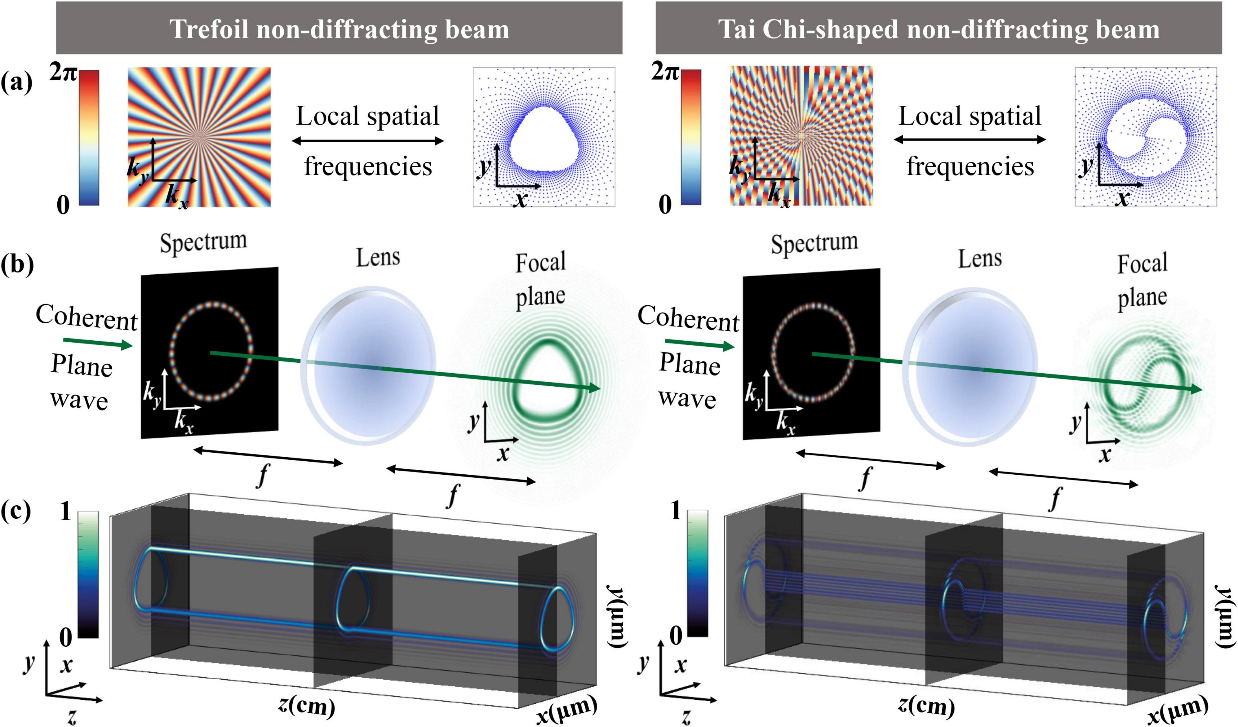
Figure 1. Generation theory of novel non-diffracting beams via local spatial frequency mapping. (a) Mapping of phase and local spatial frequency; (b) Schematic of the Fourier transformation applied to annular spatial spectra; (c) Simulated propagation processes. Left: Trefoil non-diffracting beam; Right: Tai Chi-shaped non-diffracting beam constructed by “cutting and splicing”.
From an intuitive perspective, Eq. (2) also suggests a reverse design possibility: the intensity profile of a target optical field can be reduced to a two-dimensional curve defined by coordinate points (x, y). The corresponding phase modulation j(kx, ky) on the Fourier plane can, in principle, be derived from this curve via an integral operation. In practice, however, this process is generally prohibitively complex. Notably, the unique spectral structures of non-diffracting beams can significantly simplify this problem. Given that kr is constant, the required phase modulation depends solely on the azimuthal coordinate qk. Consequently, the local spatial frequency at point (kr, qk) on the Fourier plane, i.e., the gradient of j(qk), can be mapped directly to the point (r, q) in real space satisfying that ∂j/∂kr = 0, ∂j/∂qk = r, and qk = q + sign(∂j/∂qk) p/2. Accordingly, Eq. (2) can be simplified, and the phase modulation on the Fourier plane is expressed as:
where r(q) denotes the curve function representing the intensity profile of the target non-diffracting beam, and s = ±1 represents the orientation of the phase gradient.
By performing a Fourier transform on the phase-modulated annular spatial spectrum, a non-diffracting beam is generated at the back focal plane of the lens, with its transverse intensity profile reproducing the intended shape (Figure 1b). In real space, the origin of the coordinate (x, y, z) is defined at this focal point. The optical field at the plane z = 0 serves as the initial condition for the propagation simulations shown in (Figure 1c). Since the annular spectrum satisfies Eq. (1), the resulting beam meets the rigorous definition of a non-diffracting beam, as confirmed by its propagation-invariant intensity distribution during free-space propagation.
More importantly, the proposed customizable non-diffracting beam, achieved through local spatial frequency mapping, is not only compatible with the conventional phase design but also facilitates more flexible spectrum engineering by cutting and splicing phase patterns. For example, we demonstrate a Tai Chi-shaped profile mapping from a splicing phase, and simulate its non-diffracting propagation, as shown in the right panel of Figure 1. This approach substantially expands the freedom in tailoring custom optical intensity distributions.
As a specific example, we generate the non-diffracting beams with polygonal intensity profiles, whose main lobe forms a closed curve described by the function.
Correspondingly, the phase modulation of the annular spectrum (with radii kr) can be calculated as:
where m defines the phase variation range, n decides the side number of the polygon, and l represents the topological charge of the vortex phase. This phase distribution has the same expression form as our previously reported azimuthal sine-vortex phases[43]. Typical phase distributions are shown in Figure 2a1,b1,c1,d1. Distributions of local spatial frequencies for various parameters are shown in Figure 2a2,b2,c2,d2, and the corresponding intensity distributions calculated from Eq. (1) are presented in Figure 2a3,b3,c3,d3. The parameters are selected as follows: m = 1; (a, b) n = 3, l = 0 and 30; (c, d) n = 4 and 5, l = 30. The beam’s spatial intensity profile is governed by three key parameters: the topological charge l controls the beam radius; n determines the side number of the polygonal profile; and m enables proportional scaling of the polygonal base (Section S1). This parametric control allows precise engineering of the beam’s spatial characteristics while preserving its non-diffracting properties.
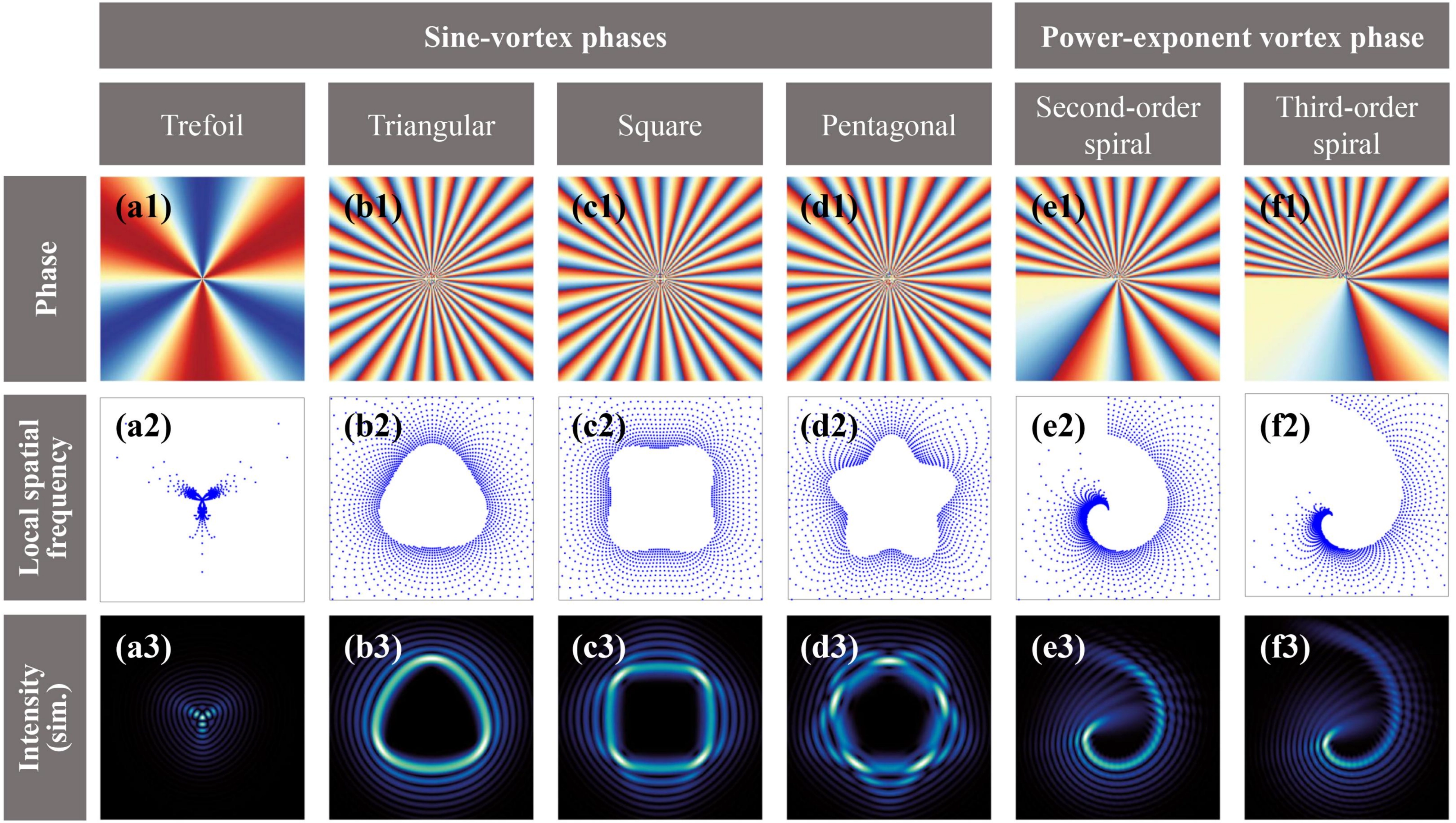
Figure 2. Non-diffracting beams with distinct profiles constructed by sine-vortex phases and power-exponent vortex phase. Top: Phase distributions; Middle: Spot diagrams of local spatial frequencies; Bottom: Simulated normalized intensity distributions in real space.
Another example is the spiral intensity distribution described by the curve:
which is governed by a power-exponent vortex phase[44] as follows.
By adjusting parameters n and l, the spiral intensity distribution of the beam in real space can also be controlled. The corresponding spectral phase, local spatial frequency, and intensity distributions are shown in Figure 2e,f, where l = 20, n = 2 and 3, respectively.
Notably, the proposed method relies on a point-to-point mapping, which can be compromised when the curve function r(θ) contains inflection points, as these may generate multiple overlapping rays. This issue can be resolved by applying the spectrum-splicing method via Eq. (7) in Section 3.2. Within the overlapping region, the local phase corresponds to a grating structure capable of supporting a multivalued mapping. The local spatial frequency point maps (middle row of Figure 2), computed from Eqs. (4) and (6), show a clear correspondence with the spatial intensity distributions (bottom row of Figure 2) obtained via the Whittaker integral under the phase modulations given by Eqs. (3) and (5). In particular, the density of these points reflects the local energy concentration, with denser regions corresponding to higher optical intensity in the real-space field. A comparison of this relationship is provided in Section S3.
3. Results and Discussion
3.1 Experimental generation of novel non-diffracting beams
To validate the simulation results and produce novel non-diffracting beams with prescribed intensity profiles, we employed the experimental setup illustrated in Figure 3a. An expanded and collimated laser beam (λ = 532 nm) was split by a beam splitter (BS1) into two components: an object beam for generating non-diffracting beams, and a reference beam for phase measurement. The object beam was modulated by a phase-only computer-generated hologram (CGH) (as shown in Figure 3b), which was loaded onto a spatial light modulator (SLM, HOLOEYE Photonics AG, 1,920 × 1,080 pixels, 8 µm pixel pitch). This modulated beam was then filtered by a 4f system comprising lenses L1 and L2 (both with a focal length of 20 cm) and an aperture filter F (diameter of 1-4 mm). The CGH, functioning as an off-axis hologram, was calculated by an amplitude-encoding technique[10]. In combination with the 4f filtering system, it enabled complex amplitude modulation, producing an annular amplitude profile and the designed spectral phase. After a subsequent Fourier transformation executed by lens L3 (focal length of 10 cm), the resulting non-diffracting beam was generated at the back focal plane of L3 and directly captured by a CCD camera. To examine the phase property of the non-diffracting beam, the interference field between the reference and resulting beams was recorded and subsequently analyzed using a phase-reconstruction method based on digital holography[45], thereby retrieving the phase distribution of the light field.
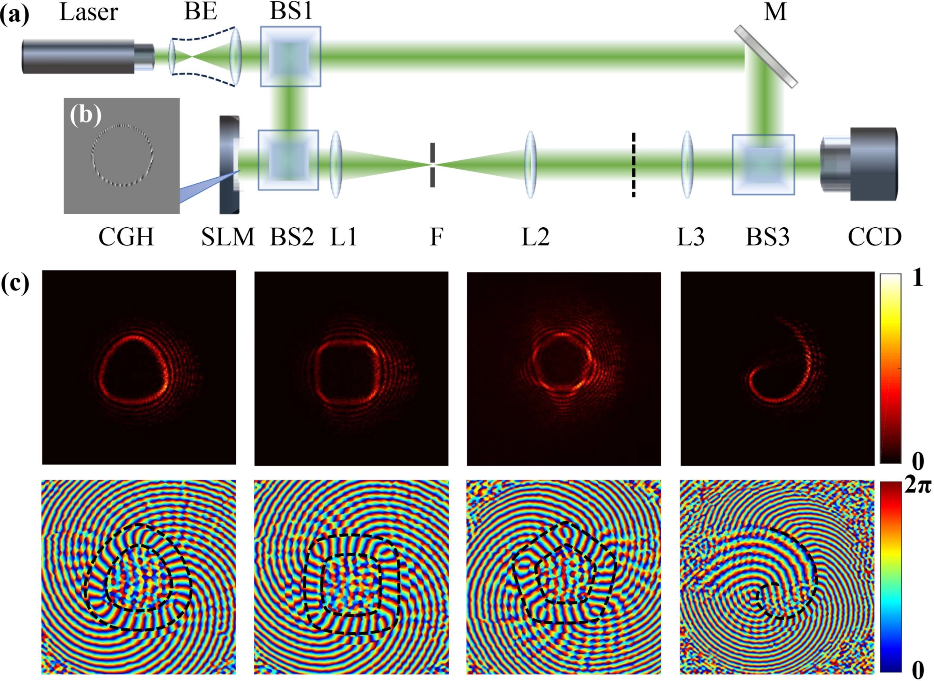
Figure 3. Experimental generation and characterization of non-diffracting fields. (a) Schematic of the optical setup. BE: beam expander; (b) CGH encoded on the SLM; (c) Experimental results of (top) intensity and (bottom) phase distributions for trefoil, square, pentagonal, and spiral non-diffracting fields. BS: beam splitter; M: mirror; SLM: spatial light modulator; L: lens; F: aperture filter; CGH: computer-generated hologram.
Figure 3c presents the experimental results of the intensity profiles (top) and the reconstructed phase distributions (bottom) for the generated non-diffracting beams. The intensity profiles closely corroborate their simulated counterparts in Figure 2b3,c3,d3,e3, exhibiting main lobes with trefoil, quadrilateral, pentagonal, and second-order helical geometries, respectively. Radially decaying side lobes with the corresponding shapes are also observable. A spatial correspondence is evident in the phase distributions, where the patterns within the black dashed curves align with the intensity profiles. For the polygonal non-diffracting beam, with l = 30 selected in Eq. (3), the reconstructed phases display 30-order vortex phase structures within the closed black curves. This experimental demonstration confirms the efficacy of the proposed approach.
Subsequently, the propagation invariance and self-healing properties of the trefoil non-diffracting beams were systematically examined. To visualize the beam’s evolution, the CCD was moved longitudinally to capture the intensity distributions step by step. The propagation invariance of a trefoil non-diffracting beam is demonstrated in Figure 4a, which shows its experimental intensity evolution over 18 cm in the y-z plane. For comparison, Figure 4b presents the propagation of a Bessel beam with an identical transverse wave vector kr. White dashed lines in Figure 4a,b demarcate the respective non-diffracting ranges (~14 cm), defined by the locations of the half-maximum intensities. Owing to the asymmetry of the trefoil beam, the non-diffracting range was calculated based on the lobe exhibiting more rapid intensity decrease (the upper lobe in Figure 4a). The nearly identical non-diffracting distances reveal that the phase modulation of the annular spectrum modifies the beam morphology without affecting its non-diffracting performance.
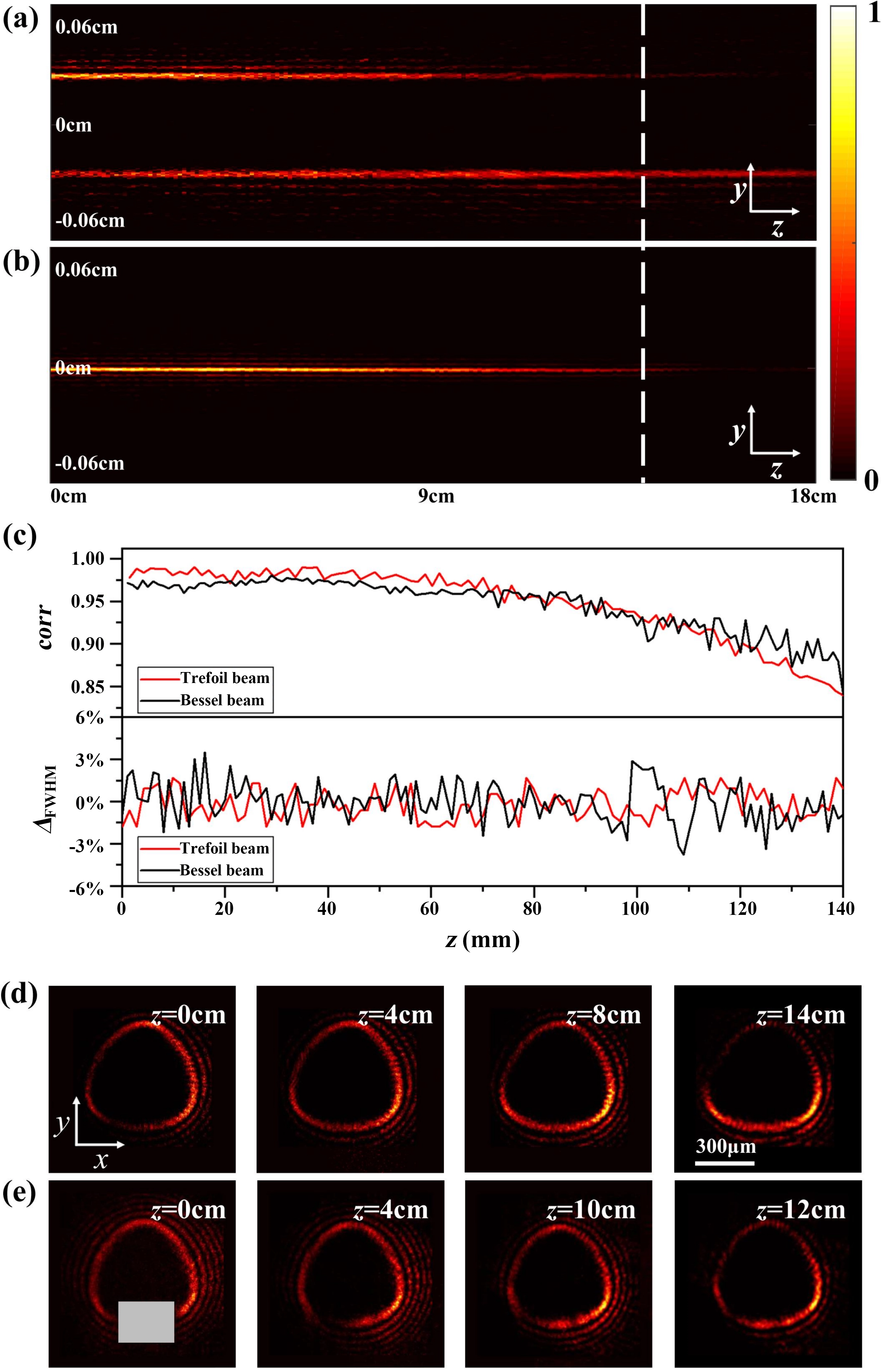
Figure 4. Propagation dynamics and self-healing properties of the generated non-diffracting beams. (a, b) Propagation processes in y-z plane for trefoil and Bessel beams; (c) Evolution curves (red lines) of the main lobe FWHM and the Pearson correlation coefficient for trefoil beam, compared with those of the Bessel beam (black lines); (d) Transverse intensity distributions of the trefoil non-diffracting beam at different distances; (e) Transverse intensity evolution when obstructed by an obstacle (marked by the gray rectangle). FWHM: full width at half maximum.
The theoretical effective propagation distance of a non-diffracting beam is primarily determined by the annular radii in the spectral plane and the numerical aperture of the lens (Figure 1b). Experimentally, however, the observed non-diffracting distance is typically shorter than this theoretical prediction due to several limiting factors. The two primary factors are: (1) the clear aperture of the light field, which is determined by the aperture filter size governed by the phase grating spacing of the CGH; and (2) the transverse wave vector of the generated beam, which is determined by the radii of the annular spectrum loaded onto the SLM and the focal lengths of lenses L1, L2, and L3. Additionally, the width of the annular spectrum also influences the non-diffracting distance to some extent. Consequently, under the current experimental configuration, the maximum non-diffracting distance achieved for the generated beam is approximately 14 cm. This study focuses on the generation of shape-tunable non-diffracting beams without optimizing generation efficiency. The experimental setup employed an SLM combined with a 4f system for complex amplitude modulation, which is not optimal in terms of energy utilization. To improve efficiency in practical applications, an axicon lens could be placed before the SLM to enforce stricter annular spectrum modulation by loading only the modulation phase onto the SLM, thereby enhancing beam generation efficiency.
To quantitatively assess the propagation invariance of the non-diffracting beam, we adopted two metrics: the Pearson correlation coefficient corr (defined as the ratio of the covariance between the two field intensities to the product of their standard deviations; see Eq. (S4)), and the relative variation of the full width at half maximum (FWHM) of the main lobe (expressed as ∆FWHM, defined as the relative error of FWHM). As shown in the top part of Figure 4c, the evolution of the Pearson correlation coefficient reflects the fidelity of the beam profile during propagation. The reduction of the coefficient to 0.84 is primarily attributed to the overall decrease in intensity and the slight collapse of side lobes due to diffraction, while the intensity distributions maintain their overall fidelity. Over an experimentally measured propagation range of 14 cm, 100 transverse intensity profiles were acquired periodically to analyze the variation of the main-lobe FWHM. As shown in the bottom part of Figure 4c, the relative deviation of the main-lobe width remains within ±2.5 % throughout the entire propagation distance. This minor fluctuation is likely to be attributed to inherent limitations of the experimental setup, such as the finite pixel size and noise floor of the CCD camera. These results indicate that, within the verified propagation range, the main-lobe size of the trefoil non-diffracting beam remains relatively stable, thereby confirming its reasonably good propagation invariance. By comparison with the results for a zero-order Bessel beam, the observed non-diffracting properties exhibit a high degree of consistency with those of a Bessel beam.
Figure 4d shows the transverse intensity distributions of the trefoil beam at different propagation distances, demonstrating its profile-preserving property. To evaluate the self-healing capability, an obstruction (gray rectangle in Figure 4e) was placed 6 cm after lens L3. Figure 4e depicts the beam’s reconstruction process, confirming that it recovers its initial profile after propagating 10 cm past the obstacle. To quantitatively evaluate the self-healing performance, the recovered beam profiles are compared with the unobstructed counterparts at the same propagation distance, as detailed in Figure S4. The Pearson correlation coefficient increases significantly from 0.412 at z = 0 cm to 0.858 at z = 10 cm, demonstrating that the trefoil non-diffracting beam achieves effective self-healing. To further demonstrate the self-healing properties of the trefoil non-diffracting beam, we present additional numerical results (Section S4 and Section S6). These results illustrate the influence of obstacle size, shape, and position on the self-healing performance, quantified via Pearson correlation coefficients, for trefoil beams with varying topological charges. A comparative analysis with Bessel beams is also provided. Collectively, the findings confirm the robust self-healing capability of trefoil non-diffracting beams.
3.2 Generation of complex non-diffracting beams through spatial spectrum splicing
In this section, we introduce a flexible method for generating non-diffracting beams with customized complex intensity profiles by engineering the local spatial frequency. This is accomplished by cutting and splicing the spatial frequency, which corresponds to the real-space intensity distribution, derived from the phase-modulated annular spatial spectrum. Assuming that the intensity profile of a non-diffracting beam can be decomposed into N parts, where the jth component is mapped from a phase component φj, the total phase distribution of the annular spectrum is expressed in a spliced form as follows.
The arg(·) function is employed to adopt a pure-phase representation, ensuring theoretical consistency. Physically, this representation corresponds to the coherent superposition of multiple complex amplitudes. In practice, the complex form of the angular spectrum, i.e.
Figure 5 demonstrates a typical application of the spectrum-splicing method, presenting a right-trapezoid non-diffracting beam formed by combining sheared square and trefoil components. Given that the partially blocked vortices cause a relative 90° rotation for the intensity distributions in the Fourier domain, which can be precisely determined by the blocking range[46,47], we retain the phase from Figure 2c1 solely within the angular region θk ∈ [π, 2π] and eliminate the extraneous portion to generate a non-diffracting beam with a left-half-square intensity profile, as illustrated in Figure 5a1. The corresponding local spatial frequency density distribution and intensity profile are computed and presented in Figure 5a2,a3, respectively. Similarly, preserving the phase of Figure 5b1 for θk ∈ [0, π] yields a right-half-trefoil intensity profile, shown in Figure 5b. To align these two components, an additional phase gradient was applied to the trefoil phase to shift the local spatial frequency. By splicing the half-square and half-trefoil phase patterns, the modulation phase necessary for producing a right-trapezoidal non-diffracting beam is constructed, as demonstrated in Figure 5c. The bottom of Figure 5 presents the experimental results of the individual components and the synthesized beam generated by the setup in Figure 3a, demonstrating agreement with theoretical predictions.
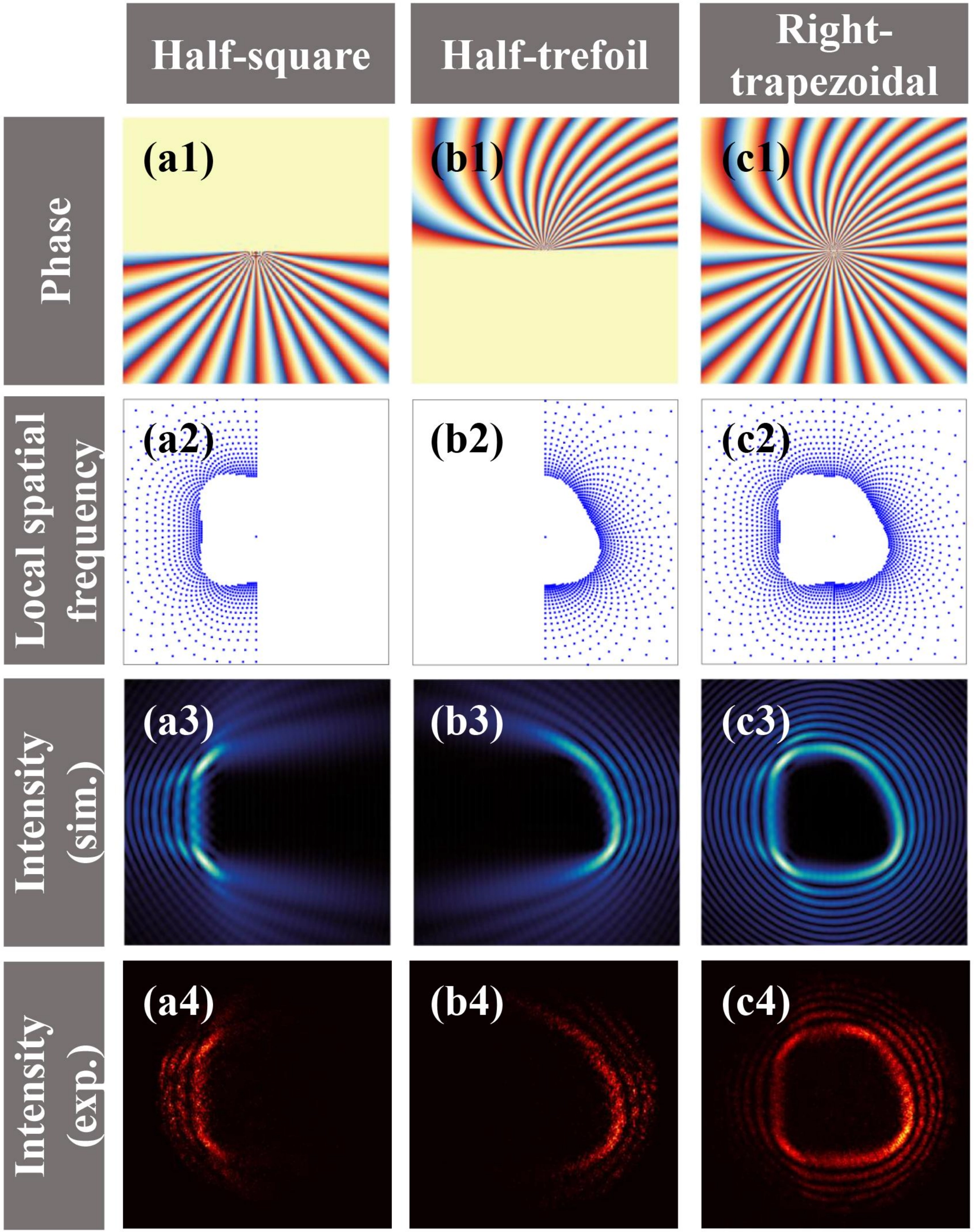
Figure 5. Construction of a right-trapezoid non-diffracting beam via phase cutting and splicing. (a, b) Individual beam components; (c) Synthesized beam. From top to bottom: designed phase distributions in Fourier domain, spot diagrams of the local spatial frequencies for the phases, simulated real-space intensity distributions, and experimental captured intensity profiles, respectively.
The proposed spectrum splicing method facilitates the generation of non-diffracting beams with more complex structures. Figure 6 illustrates three representative examples of such beams, featuring Tai Chi-shaped, gourd-shaped, and heart-shaped patterns. In the case shown in Figure 5, the two phase components are complementary and do not interfere with each other, resulting in a regularly distributed synthesized phase. For the more general cases depicted in Figure 6, phase components typically overlap; the phase in overlapping regions is managed using the arg(·) function, as specified in Eq. (7). The overlapping phase region exhibits a grating-like structure, which generates two distinct rays corresponding to two different local spatial frequencies. These discontinuous local spatial frequencies correspond to the inflection points in the intensity distributions. Figure 6a1,b1,c1 show the complex modulation phases for these beams, with detailed phase splicing processes provided in Section S2. Figure 6a2,b2,c2 present the corresponding local spatial frequency distributions, where distinct phase components are color-coded. Figure 6a3,b3,c3 and Figure 6a4,b4,c4 display the simulated and experimentally measured intensity distributions of these beams, respectively, demonstrating alignment with the local spatial frequency patterns.
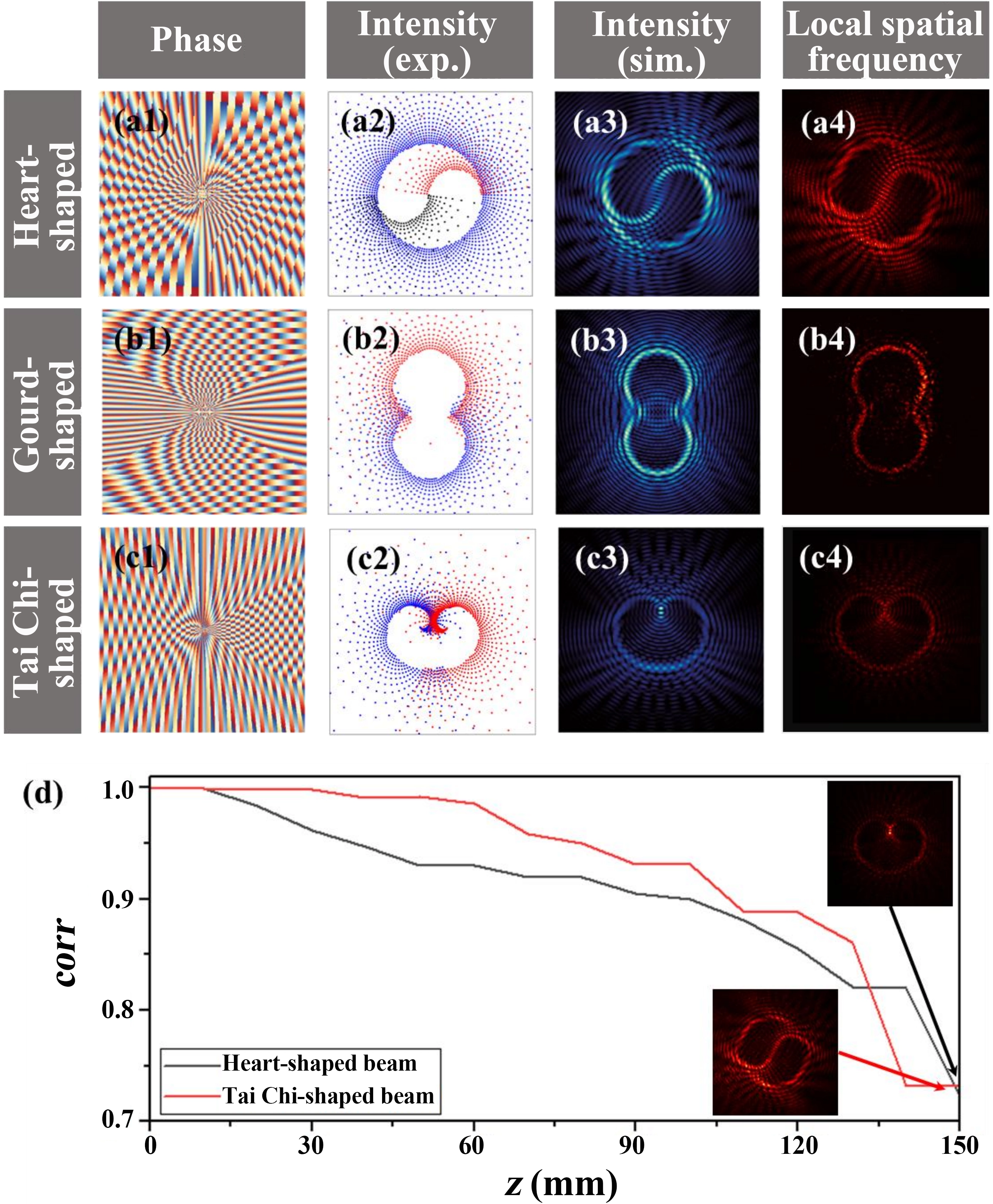
Figure 6. Non-diffracting beams with more complex shapes. (a1)-(c1) Phase distributions of Tai Chi-shaped, gourd-shaped, and heart-shaped non-diffracting beams; (a2)-(c2) Spot diagrams of local spatial frequencies; (a3)-(c3) Simulated intensity distributions; (a4)-(c4) Experimental intensity results; (d) Evolution of Pearson correlation coefficients for the Tai Chi-shaped and heart-shaped beams.
The propagation-invariant characteristics of the Tai Chi-shaped and heart-shaped non-diffracting beams were experimentally verified, as visualized by Supplementary Material 2 and 3. The evolution of the Pearson correlation coefficients for these beams, presented in Figure 6d, quantitatively confirms their non-diffracting nature. At a propagation distance of 14 cm, the correlation coefficients for these beams (0.82 and 0.74) are slightly lower than that of the Bessel beam (0.85; see Figure 6c), indicating that the discontinuous points introduced by beam splicing reduce the non-diffracting performance. Although the Tai Chi-shaped beam possesses more discontinuous points, its correlation coefficient evolves similarly to that of the heart-shaped beam up to a distance of z = 14 cm. These results indicate that such intricately structured beams can basically maintain their transverse intensity profiles over extended propagation distances.
We further present simulation results on the self-healing behavior of the Tai Chi-shaped beam with varying obstacle positions (Section S5). The Pearson correlation coefficients indicate a preliminary recovery of the beam structure (exceeding 0.7) after a short propagation distance (z = 5 cm), with near-complete recovery (above 0.98) upon further propagation (z = 10 cm) across all tested obstacle positions. These results confirm that, even under the complex phase background generated by interference superposition, the Tai Chi-shaped beam retains a robust self-healing capability.
To assess the applicability to more complex structured beams, we simulated the propagation of non-diffracting beams with multi-aperture-shaped, flower-shaped and number-shaped profiles (Figure S14,S15,S16). These results quantitatively confirm that even with complex phase structures containing multiple discontinuities, the non-diffracting performance of the complex-spliced beams does not degrade significantly, exhibiting excellent propagation invariance. As the propagation distance approaches the non-diffraction limit, minor interference emerges among the profiles, accompanied by a decrease in the Pearson correlation coefficient below 0.9. Furthermore, for the most complex configuration, a random-phase-modulated annular spectrum was utilized to generate a non-diffracting beam with a speckle-like pattern (Figure S17). Although the Pearson correlation coefficient for the random-phase beam decreases more rapidly than that of the well-defined beams, primarily because diffraction effects manifest more intensely within the uniform lobe distribution, it remains at a higher value over a certain propagation distance, indicating a degree of propagation stability.
4. Conclusion
In summary, we propose an approach for generating non-diffracting beams with customizable intensity profiles through phase modulation of their spatial spectrum. By applying the theory of local spatial frequency mapping, we establish a correspondence between the phase in Fourier space and the intensity profile in real space, and propose a computational method for phase modulation of the annular spectrum based on a simplified curve function derived from the light intensity distribution. As illustrative examples, non-diffracting beams with polygonal and spiral profiles are generated, and their non-diffracting and self-healing properties are verified both numerically and experimentally. To generate non-diffracting beams with more complex profiles, a spatial spectrum splicing technique is introduced, offering an effective approach for customizing beam morphologies. Several novel non-diffracting beams, including trapezoidal, Tai Chi-shaped, and numeral-shaped profiles, are demonstrated. The results indicate that phase modulation in Fourier space does not compromise these inherent non-diffracting characteristics, while phase discontinuities and multivalued rays arising from imperfect splicing exhibit minimal influence. This method enables precise manipulation of complex optical fields, offering potential for applications in high-precision laser machining, optical trapping, free-space communication, and structured-light imaging[44].
Although the proposed method effectively addresses the constraint issues associated with inflection points in the objective function within caustic theory, its reliance on spatially dispersive Bessel-based functions limits the capacity for fully customizing non-diffracting beams. Furthermore, in complex splicing configurations, the method introduces inevitable phase discontinuities that can slightly degrade the non-diffracting characteristics. Additionally, the inverse design technique for phase modulation implemented here is currently limited to the reverse solution of special functions. To enable the customization of non-diffracting beams with higher morphological complexity, the required numerical methods for intensity distributions described by arbitrary closed curves require further exploration.
Supplementary materials
The supplementary material for this article is available at: Supplementary materials.
Authors contribution
Liu S: Conceptualization, supervision, writing-review & editing.
Li P, Zhao J: Supervision, writing-review & editing.
Zhang Y, Wang W: Investigation, formal analysis, writing-original draft, writing-review & editing.
Guo Z, Zou Y, Li Y, Fan X: Methodology.
Wei B, Wen D, Zhang Y: Writing-review & editing.
Conflicts of interest
Jianlin Zhao is an Editorial Board Member of Light Manipulation and Applications. The other authors declare no conflicts of interest.
Ethical approval
Not applicable.
Consent to participate
Not applicable.
Consent for publication
Not applicable.
Availability of data and materials
The data that support the findings of this study are available from the corresponding author upon reasonable request.
Funding
This work was supported by the National Key Research and Development Program of China (Grant No. 2022YFA1404800), National Natural Science Foundation of China (Grant No. 12474338, No. 12474298, No. 62305271, No. 62175200, No. 12374279, No. 62475217, No. 62575240 and No. 62305271), and Fundamental Research Funds for the Central Universities (Grant No. 5110240015).
Copyright
© The Author(s) 2026.
References
-
1. Durnin J. Exact solutions for nondiffracting beams. I. J Opt Soc Am A. 1987;4(4):651.[DOI]
-
3. Gutiérrez-Vega JC, Iturbe-Castillo MD, Ramı́rez GA, Tepichı́n E, Rodrı́guez-Dagnino RM, Chávez-Cerda S, et al. Experimental demonstration of optical Mathieu beams. Opt Commun. 2001;195:35-40.[DOI]
-
5. Sosa-Sánchez CT, Silva-Ortigoza G, Juárez-Reyes SA, Cabrera-Rosas ODJ, Espíndola-Ramos E, Julián-Macías I, et al. Parabolic non-diffracting beams: Geometrical approach. J Opt. 2017;19(8):085604.[DOI]
-
6. Siviloglou GA, Christodoulides DN. Accelerating finite energy Airy beams. Opt Lett. 2007;32(8):979-981.[DOI]
-
7. Bouchal Z, Wagner J, Chlup M. Self-reconstruction of a distorted nondiffracting beam. Opt Commun. 1998;151:207-211.[DOI]
-
8. Broky J, Siviloglou GA, Dogariu A, Christodoulides DN. Self-healing properties of optical Airy beams. Opt Express. 2008;16(17):12880-12891.[DOI]
-
11. Guo Y, Zhang S, Pu M, He Q, Jin J, Xu M, et al. Spin-decoupled metasurface for simultaneous detection of spin and orbital angular momenta via momentum transformation. Light Sci Appl. 2021;10:63.[DOI]
-
12. Wang G, Zhou T, Huang J, Wang X, Hu B, Zhang Y. Moiré meta-device for flexibly controlled Bessel beam generation. Photon Res. 2023;11(1):100-108.[DOI]
-
13. Nan T, Zhao H, Guo J, Wang X, Tian H, Zhang Y. Generation of structured light beams with polarization variation along arbitrary spatial trajectories using tri-layer metasurfaces. Opto-Electron Sci. 2024;3(5):230052.[DOI]
-
14. Liu X, Gu M, Tian Y, Zheng M, Fang B, Hong Z, et al. Research progress on generating perfect vortex beams based on metasurfaces. Opto-Electron Sci. 2025;4(11):250007.[DOI]
-
15. Dorrah AH, Palmieri A, Li L, Capasso F. Rotatum of light. Sci Adv. 2025;11(15):eadr9092.[DOI]
-
16. Zou Y, Li Y, Yan J, Liu H, Zhang Y, Zhang Y, et al. On-demand longitudinal transformations of light beams via an amplitude-phase-decoupled pancharatnam-berry phase element. Laser Photonics Rev. 2026;20(5):e02167.[DOI]
-
19. Mathis A, Courvoisier F, Froehly L, Furfaro L, Jacquot M, Lacourt PA, et al. Micromachining along a curve: Femtosecond laser micromachining of curved profiles in diamond and silicon using accelerating beams. Appl Phys Lett. 2012;101(7):071110.[DOI]
-
20. Courvoisier F, Stoian R, Couairon A. Ultrafast laser micro- and nano-processing with nondiffracting and curved beams. Opt Laser Technol. 2016;80:125-137.[DOI]
-
21. Meyer R, Giust R, Jacquot M, Dudley JM, Courvoisier F. Submicron-quality cleaving of glass with elliptical ultrafast Bessel beams. Appl Phys Lett. 2017;111(23):231108.[DOI]
-
23. Dholakia K, Čižmár T. Shaping the future of manipulation. Nat Photonics. 2011;5(6):335-342.[DOI]
-
24. Woerdemann M, Alpmann C, Esseling M, Denz C. Advanced optical trapping by complex beam shaping. Laser Photonics Rev. 2013;7(6):839-854.[DOI]
-
26. Li S, Wang J. Adaptive free-space optical communications through turbulence using self-healing Bessel beams. Sci Rep. 2017;7:43233.[DOI]
-
27. Hu J, Guo Z, Shi J, Jiang X, Chen Q, Chen H, et al. A metasurface-based full-color circular auto-focusing Airy beam transmitter for stable high-speed underwater wireless optical communications. Nat Commun. 2024;15:2944.[DOI]
-
28. Xu H, Cheng J, Zhao S, Guan S, Li F, Wang X, et al. Terahertz 4D Bessel beam steering and near-field communications by cascaded metasurfaces. Laser Photonics Rev. 2026;20(6):e01805.[DOI]
-
30. Fahrbach FO, Simon P, Rohrbach A. Microscopy with self-reconstructing beams. Nat Photonics. 2010;4(11):780-785.[DOI]
-
34. Tan L, Huo P, Lin P, Ren Y, Qi H, Fang L, et al. Longitudinally engineered metasurfaces for 3D vectorial holography. Light Sci Appl. 2026;15:36.[DOI]
-
35. Zannotti A, Denz C, Alonso MA, Dennis MR. Shaping caustics into propagation-invariant light. Nat Commun. 2020;11:3597.[DOI]
-
37. Chen R, Shi Y, Gong N, Liu Y, Ren Z. Generation of shaping nondiffracting structured caustic beams on the basis of stationary phase principle. Chin Opt Lett. 2023;21(10):102601.[DOI]
-
38. Huo P, Yu R, Liu M, Zhang H, Lu YQ, Xu T. Tailoring electron vortex beams with customizable intensity patterns by electron diffraction holography. Opto-Electron Adv. 2024;7(2):230184.[DOI]
-
39. Yun X, Liang Y, He M, Guo L, Zhang X, Wang S, et al. High-efficiency generation of long-distance, tunable, high-order nondiffracting beams. Photonics Res. 2024;12(10):2390-2400.[DOI]
-
40. Alonzo CA, Rodrigo PJ, Glückstad J. Helico-conical optical beams: A product of helical and conical phase fronts. Opt Express. 2005;13(5):1749-1760.[DOI]
-
41. Bouchal Z. Nondiffracting optical beams: Physical properties, experiments, and applications. Czech J Phys. 2003;53(7):537-578.[DOI]
-
42. Whittaker ET. On the partial differential equations of mathematical physics. Math Ann. 1903;57(3):333-355.[DOI]
-
45. Schnars U, Jueptner W. Digital holography. Heidelberg: Springer; 2005. Available from: https://link.springer.com/book/10.1007/b138284
-
46. Wang XL, Lou K, Chen J, Gu B, Li Y, Wang HT. Unveiling locally linearly polarized vector fields with broken axial symmetry. Phys Rev A. 2011;83(6):063813.[DOI]
Copyright
© The Author(s) 2026. This is an Open Access article licensed under a Creative Commons Attribution 4.0 International License (https://creativecommons.org/licenses/by/4.0/), which permits unrestricted use, sharing, adaptation, distribution and reproduction in any medium or format, for any purpose, even commercially, as long as you give appropriate credit to the original author(s) and the source, provide a link to the Creative Commons license, and indicate if changes were made.
Publisher’s Note
Science Exploration remains a neutral stance on jurisdictional claims in published
maps
and institutional affiliations. The views expressed in this article are solely those
of
the author(s) and do not reflect the opinions of the Editors or the publisher.
Share And Cite


Science Exploration Style
Zhang Y, Wang W, Guo Z, Zou Y, Li Y, Fan X, et al. Novel non-diffracting beams engineered via localized spatial frequency mapping. Light Manip Appl. 2026;1:202505. https://doi.org/10.70401/lma.2026.0008
Tips
Copy completed.
Submit a Manuscript
Author Instructions
Cite this Article
Article Metrics
0
View
0
Download
Cited
Article Updates

Science Exploration Style
Zhang Y, Wang W, Guo Z, Zou Y, Li Y, Fan X, et al. Novel non-diffracting beams engineered via localized spatial frequency mapping. Light Manip Appl. 2026;1:202505. https://doi.org/10.70401/lma.2026.0008
copy
Share Link
copy