High-performance electrocaloric cooling devices for efficient and compact solid-state refrigeration Download PDF
*Correspondence to:
Xiaoshi Qian, State Key Laboratory of Mechanical System and Vibration, Interdisciplinary Research Center, Institute of Refrigeration and Cryogenics, MOE Key Laboratory for Power Machinery and Engineering, School of Mechanical Engineering, Shanghai Jiao Tong University, Shanghai 200240, China.
E-mail: xsqian@sjtu.edu.cn
Thermo-X. 2025;1:202505. 10.70401/tx.2025.0004
Received: June 10, 2025Accepted: September 22, 2025Published: September 26, 2025
Abstract
The electrocaloric (EC) effect represents the changes of polarization entropy and/or temperature of dielectrics when an external electric field is applied and removed. An efficient EC effect relies on a highly reversible conversion between electrical energy and thermal energy. Based on this effect, EC refrigeration has demonstrated advantages in terms of high energy efficiency, zero direct carbon emissions, and high specific volumetric cooling power densities. Consequently, EC refrigeration is recognized as one of the promising alternative technologies for next-generation refrigeration and heat pump. Over the past two decades, EC cooling devices have been extensively developed, driven by advances in EC materials and working bodies. In this review, we summarize recent progress in EC cooling devices, focusing on the mechanisms of solid-state refrigerants and thermodynamic cycles within these systems, and highlighting the characteristics of devices operating on different working principles.
Graphical Abstract
Keywords
Electrocaloric cooling devices, active electrocaloric regeneration, self-actuating devices, cooling abilities, enthalpy difference platform
1. Introduction
Refrigeration has quietly transformed nearly every aspect of modern technology over the last two hundred years. The future advancement of science and technology and the goal of continuous improvement of human living standards, demand the technical leap of localized and targeted active thermal management[1]. These ever demanding callsstimulate new urges for the innovation of refrigeration technology as illustrated in Figure 1A. For instance, high-performance chips require precise cooling during operation, as excessive heat can reduce computational performance. Similarly, the local heat generated by active joints in complex machinery, such as robots, requires precise heat dissipation on motors, actuators, power electronics, and etc. Compared with large open-space air conditioning (A/C), localized cooling in specific areas, such as room seats or car seats, can offer comfortable temperature regulation for humans with lower energy consumption than that of current central A/C systems. Although the widely commercialized vapor-compression refrigeration technology and thermoelectric coolers can be adapted for localized applications under proper design considerations, solid-state cooling technologies, including magnetocaloric (MC)[2-4], elastocaloric (eC)[5-8], electrocaloric (EC)[9-11], barocaloric (BC)[12-14], and thermoelectric[15,16] technologies, provide alternative technology solutions that address requirements such as system compactness, portability, noise-free, and reduced greenhouse gas emissions. Among these, EC cooling technology, based on the EC effect (ECE), has attracted widespread attention from academia and industrial world in recent years.
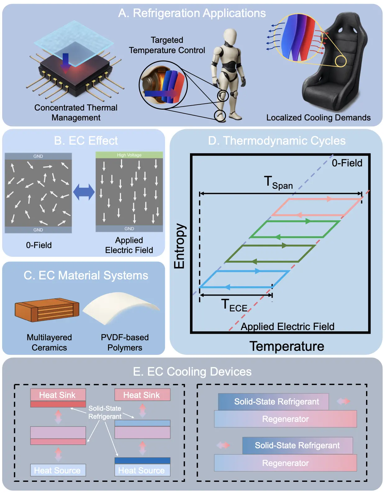
Figure 1. Foundations for the EC cooling devices. (A) Emerging refrigeration application demands in recent years; (B) Principle of the EC effect; (C) EC material systems including multilayered ceramics and PVDF-based polymers inspiring the development of EC cooling devices; (D) Thermodynamic cycles run by solid-state refrigerants; (E) Various structures of the EC cooling devices. EC: electrocaloric; PVDF: poly(vinylidene fluoride).
The ECE is phenomenologically attributed to the reorientation of dipoles (in a dielectric material) from a disordered to an ordered state in response to an electric field, first observed in Rochelle salt crystals in 1930[17], as illustrated in Figure 1B. The reversible changes in polarization entropy enable cyclical heat adsorption and ejection in these solid state materials (EC materials), forming a thermodynamic cycle for refrigeration. Theoretical demonstrations of significant ECE in dielectric ceramics in 2006[18] and in polymers in 2008[19] (Figure 1C) triggered a surge of research on ferroelectrics[20,21], including single crystals[22-24] polycrystalline oxides[25-32], molecular ferroelectrics[33,34], polymers[35-38], and their nanocomposites[39-42]. Large ECEs have also been reported in liquid crystals[43,44], expanding the field from solid-state to liquid-state applications[45]. The observation of substantial ECEs has stimulated the conceptualization and manufacture of EC cooling devices in both academia and industry. As solid-state dielectric capacitors, EC materials exhibit minimal conduction losses during thermodynamic cycling. The development of these EC materials, also referred to as solid-state refrigerants, has driven the advancement of EC cooling devices, enabling efficient operation without direct carbon emissions and maintaining a low total equivalent warming index throughout the technology’s life cycle[1,46-48].
This article provides an overview of the development of EC cooling devices from the perspective of the thermodynamic cycles of solid-state refrigerants, with particular emphasis on the role of active heat regeneration and self-actuating cooling in enhancing overall cooling performance and reducing the device complexity. It also reviews standardized testing procedures for evaluating the cooling performance of EC cooling devices and the calculation methods used, providing a reference framework for comparing the performance of various types of EC cooling devices.
2. Thermodynamic Cycles and General Structures of EC Cooling Devices
Understanding the thermodynamic cycles and general structures of EC cooling devices is fundamental for evaluating their performance and guiding future device design. The thermodynamic cycle of solid-state refrigerants in EC cooling devices is analogous to that of the vapor-compression refrigeration (VCR) process[49-51]. This cycle can also be represented on a temperature-entropy diagram, as shown in Figure 1D[52,53]. Since the loading and unloading times of the electric field are typically much shorter than the heat transfer times within the device, the solid-state refrigerant in most systems undergoes a Brayton cycle, consisting of two adiabatic processes and two isoelectric field processes. This thermodynamic cycle underpins the basic structure of EC cooling devices, in which the solid-state refrigerant alternately contacts the heat source and heat sink. The simplest EC cooling structure was established by Ju et al. in 2010, who employed a ceramic material as the EC working body and presented both simulations[54] and experimental data[55]. In their device, the EC working body was actuated vertically using a motorized z-stage. Compared with passive mechanical cycling of the working body, this configuration provided an additional cooling to 1 K by actively moving the EC working body. A similar structure was reported by Kang et al. in 2021, in which electromagnetic forces were employed to drive a polymer film between the heat source and heat sink[56]. These devices, which conduct heat primarily along a one-dimensional direction, represent a scenario in which the solid-state refrigerants undergo the same thermodynamic cycle throughout the device. However, in practice, during device operation, solid-state refrigerants at different locations often experience Brayton cycles with varying heat sources and sink temperatures, resulting in an overall cycle with a temperature span (TSpan) far exceeding the material’s adiabatic temperature change (ΔTad).
The cascaded Brayton cycles provide thermodynamic support for enhancing TSpan, guiding the development of EC cooling devices operating in the active electrocaloric regenerative (AER) cycle. For a single-stage, one-dimensional heat transfer device employing an EC material with a large ΔTad, the maximum TSpan is equal to ΔTad, which presents a challenge under the practical working conditions (TSpan ~40 K) of commercial air conditioning based on VCR. However, in a cascaded configuration, as illustrated in Figure 1E, solid-state refrigerants are arranged along the direction of motion, and both the electric field and the displacement of the refrigerants vary over the same period, resulting in a larger TSpan. In 1992, Sinyavsky et al. developed a model using ceramics as the working body, achieving a 5-K TSpan, far exceeding the ΔTad of less than 2 K[57]. Although not explicitly stated in their paper, it can be inferred that the AER cycle plays a key role in increasing the device’s temperature span.
3. Active EC Regenerative Devices with Solid Regenerators
AER devices with solid regenerators are considered a crucial approach for overcoming the limited temperature span of single-stage EC systems and for demonstrating the practical feasibility of EC cooling, with their operating principle illustrated in Figure 2A. The first device reported to employ this cycle was fabricated by Zhang’s group at Penn State University, using multilayer polymeric capacitors (MLPCs)[10,58,59]. As demonstrated by Gu et al., the MLPC consists of 24 layers of irradiated copolymer P(VDF-TrFE), EC-inactive adhesives between the layers, and stainless steel at the top and bottom (Figure 2B)[10]. In this device, solid-state refrigerants are continuously arranged along the surface of the regenerative layer, allowing the EC working bodies and regenerative layers to be modeled as continuous media, thereby significantly simplifying the device structure. The refrigeration cycle is achieved through the reciprocal movement of the MLPC on the regenerative layer, coordinated with alternating changes in the electric field. A TSpan of 5 K was obtained after 80 s operation at 100 M·Vm-1 at a frequency of 0.5 Hz (Figure 2C), indicating a twofold increase in TSpan compared with the temperature change of the EC working body (2.15 K).
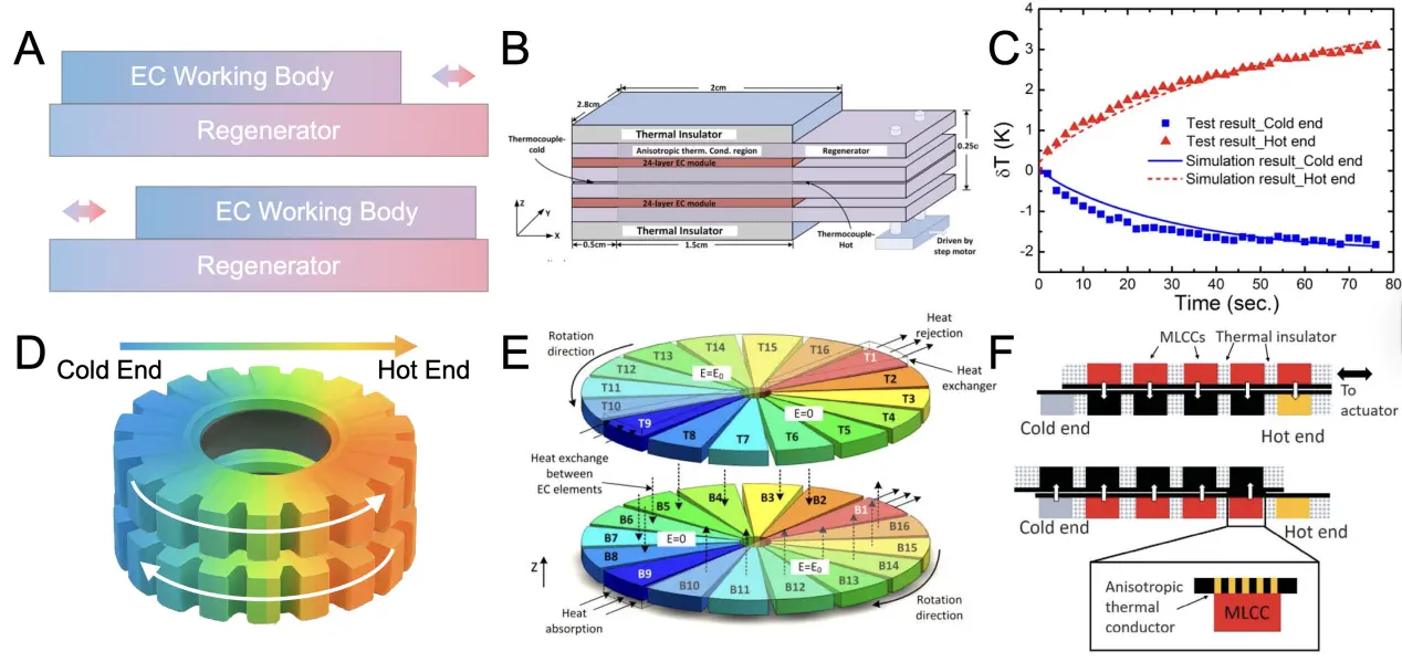
Figure 2. Active EC regenerative devices with solid-state regenerators. (A) Working principles for AER devices with solid-solid contacts; (B) First polymeric AER device developed by Zhang’s group and temperature changes of the cold and hot ends at 100 MV·m-1 and 0.5 Hz. Republished with permission from[10]; (C) Temperature response of the device; (D) Rotating AER device without extra regenerators designed by Zhang’s group that produced a 2 K temperature span; (E) Demonstration of the heat regeneration process. Republished with permission from[61]; (F) Reciprocating EC cooling device employing several PST MLCCs, showing the relative positions of the EC working bodies in the heating and cooling transfer stages. Republished with permission from[63]. EC: electrocaloric; AER: active electrocaloric regenerator; PST: PbSc0.5Ta0.5O3; MLCC: multilayer ceramic capacitor.
The cooling performance of the device can be enhanced by replacing the cooling-inactive regenerative layer with an EC-active plate. A self-regenerative EC device was subsequently developed by constructing two EC rings with multiple elements, rotated in opposite directions relative to each other (Figure 2D)[60]. The heat transfer process, illustrated in Figure 2E[61], shows the heat is regenerated along the z direction during the rotation of the upper and lower rings. In this configuration, each layer served as the regenerator for its paired layer, with both contributing to refrigeration. The prototype achieved a TSpan of 2 K when a Y5V multilayer ceramic capacitor (MLCC) was used, approximately doubling the ΔTad of 0.9 K. However, the composition of the Y5V MLCC was not optimized for the ECE, but rather for commercial capacitor applications. Therefore, in addition to optimizing the thermodynamic cycle, the limited ECE of the working bodies remained the key barrier to further improvements in device performance.
Advances in both the material and the working body have accelerated the development of AER devices. A collaborative effort between the University of Cambridge and Murata Manufacturing Co., Ltd. led to performance improvements in the ECEs of MLCCs. Nair et al. fabricated a batch of high-quality PbSc0.5Ta0.5O3 (PST) MLCCs that exhibited significant EC temperature changes of more than 5 K under an electric field of 29 V·m-1, across a wide range of starting temperatures[62]. Unlike MLCCs designed for dielectric capacitors, where the active electrode covers only a small portion of the device, EC-optimized MLCCs feature configurations with large active electrode areas to minimize thermalization with inactive materials. This study demonstrated that a substantial EC response, wide operational temperature range, optimized MLCC configuration, and high thermal conductivity facilitate efficient and rapid heat transfer, providing a promising working body for EC device research. In 2020, Wang et al. developed a linear reciprocating AER device incorporating ten PST MLCCs (Figure 2F). The device utilized a solid layer as the regenerator, with a linear motor driving the relative motion between the EC and the regenerative layer. This all-solid device exhibited a Tspan of 5.2 K and a maximum heat flux density of 0.135 W·cm-2[63]. Compared with the ΔTad (5 K) of the PST MLCC, the regeneration factor (Tspan/ΔTad, ~1.04) was modest, limited by poor heat transfer between solids. Therefore, improving the heat transfer between components remains key to further enhancing device performance.
4. Active EC Regenerative Devices with Fluidic Regenerators
Active EC regenerative devices employing fluidic regenerators represent a more effective architecture than solid-solid regeneration. The use of fluidic regenerative media in EC cooling devices facilitates efficient heat transfer, thereby increasing the device’s cooling capacity[64-67]. In devices utilizing fluidic regenerators, the fluid serves as a continuous medium for heat exchange and recovery, playing a critical role in both the cooling and energy exchange processes. In recent years, many high-performance EC cooling devices have relied on the reciprocating flow of fluids to achieve cooling, as shown in Figure 3A. For instance, the United Technologies Research Center unveiled a highly efficient EC heat pump (Figure 3B,C) in 2017[68]. Although the device was not peer-reviewed, it employed a piston to induce oscillating airflow and establish an AER with the EC working body, exhibiting a maximum TSpan of 14 K according to a U.S. Department of Energy public report.
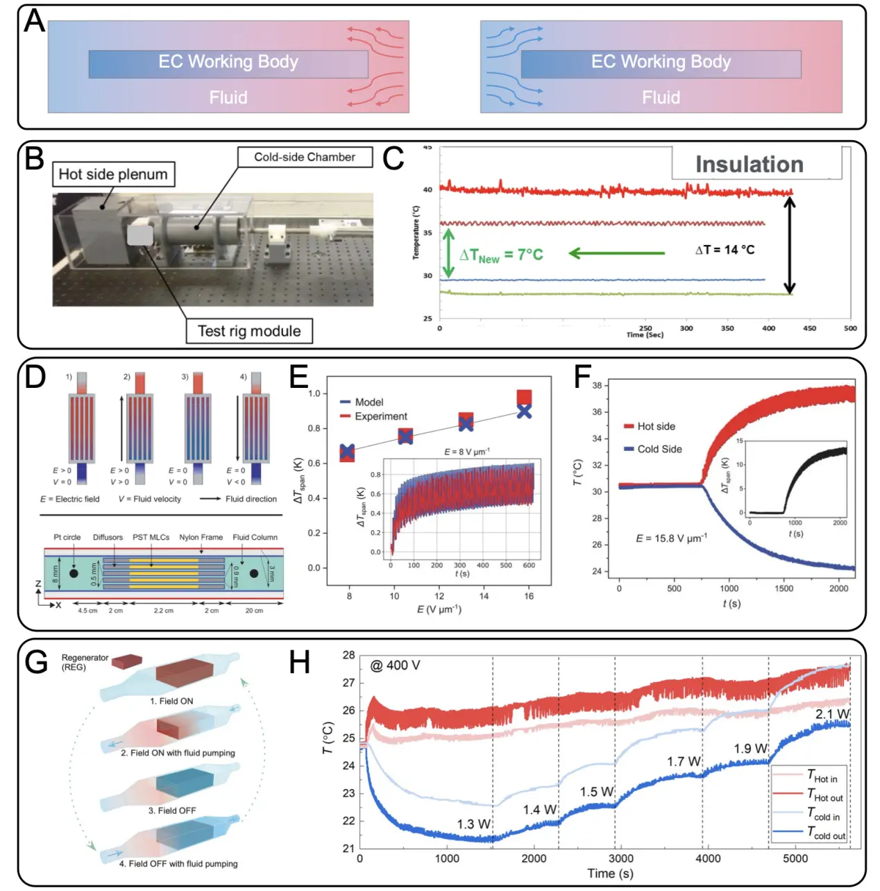
Figure 3. Active EC regenerative devices with fluidic regenerators. (A) Working principles for AER devices with liquids working as regenerators; (B) AER device employing air as the regenerating medium, fabricated at UTRC, exhibiting a temperature decrease of approximately 14 K. Republished with permission from[68]; (C) Temperature response of the device; (D) Design of the PST MLC device based on heat transfer with a fluidic regenerator; (E) Achieved temperature spans under various electric fields; (F) Temperature changes of the hot and cold sides with time at 15.8 V·µm-1. Republished with permission from[69]; (G) Double-loop-based EC cooling device with PST MLCs, showing regenerators with terminals outside (REG-TO) and terminals inside (REG-TI); (H) Changes in temperature at the hot and cold ends with increasing heater power input. Republished with permission from[11]. EC: electrocaloric; AER: active electrocaloric regenerator; PST: PbSc0.5Ta0.5O3; MLC: multilayer capacitor; UTRC: United Technologies Research Center; REG-TO: regenerator with terminals outside; REG-TI: regenerator with terminals inside.
Using the same PST MLCCs developed by Nair et al., Torelló et al. developed a device that employed a similar AER strategy, but with fluidic heat exchange media for regeneration[69]. This device demonstrated a maximum TSpan exceeding 13 K (Figure 3D,E,F), resulting in a regeneration factor greater than 2.6. Such a marked improvement in performance indicates that fluid-solid heat transfer is more effective in EC cooling devices than solid-solid heat transfer between the EC and regenerative layers.
The TSpan achieved by EC cooling devices can be further increased through structural and operational optimization. Li et al. implemented a double loop-based cooling device with PST MLCCs, achieving a maximum TSpan of 20.9 K[11]. The MLCCs used in this device were measured approximately 1 cm in length and width and 0.5 mm in thickness (Figure 3G,H), with ΔTad of ~1.7 K. Consequently, the regeneration factor is ~11.8, nearly ten times greater than that of the solid-solid heat transfer device (1.04)[63].
In recent years, EC cooling devices have also used polymeric materials as solid-state refrigerants, with fluids flowing through pipes as the heat transfer medium, taking advantage of the ease with which polymer materials can be processed into tubular forms. In 2022, Cui et al. fabricated a capillary tube from an EC polymeric nanocomposite and employed silicone oil as the heat transferring medium[70], achieving a maximum TSpan of 1.5 K with a Tad of ΔTad of 3.53 K. In 2023, Bai et al. further innovated these devices by cascading the EC tubes and applying a sawtooth voltage to facilitate multistage cooling, achieving a TSpan of 4.2 K, while the temperature drop of the tube was 4.6 K[71]. The achieved TSpan did not exceed the temperature change of the empty EC tube because AER cycles were not implemented in these devices. Therefore, with the establishment of the AER cycle, EC cooling devices employing polymeric tubes may exhibit higher cooling abilities.
5. EC Refrigerators Driven Directly by Electrostatic Forces
EC refrigerators driven directly by electrostatic forces offer a promising approach for achieving compact and lightweight cooling systems by eliminating the need for external mechanical driving components. All the EC cooling devices described above, whether purely solid-state devices or employing fluidic heat exchange media, require mechanical forces for operation, typically provided by stepper motors or pumps. These driving components complicate device structures, increasing both size and weight, which hinders the ability of EC cooling devices to realize their theoretical advantages of being lightweight and efficient. Consequently, their application in scenarios such as chip cooling and localized refrigeration remains constrained. Therefore, the development of compact, sophisticated EC cooling devices that operate without external mechanical forces has become a key focus of recent research, as illustrated in Figure 4A.
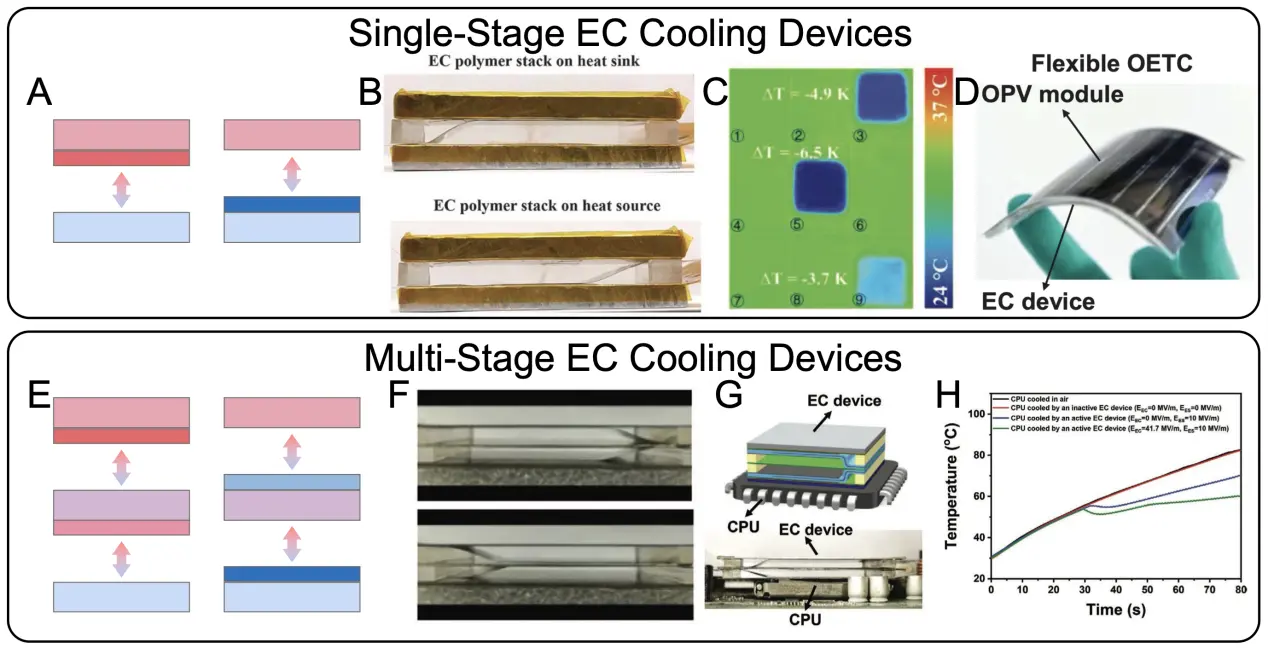
Figure 4. EC cooling devices driven by electrostatic forces. (A) Working principles for single-stage EC cooling devices; (B) Single-unit electrostatic actuating EC device with the EC polymer stack on a heat sink and heat source. Republished with permission from[73]; (C) Infrared images of a simulated CPU with three heated areas at different temperatures and a pixel-matrix EC nanocomposite stack with three activated pixels. Republished with permission from[74]; (D) Photograph of an EC clothing system assembled by an organic photovoltaics module and two EC units. Republished with permission from[75]; (F) Double-layer cascade EC device with electrostatic actuation; (G) Application of the device for CPU temperature control; (H) Temperature control results. Republished with permission from[77]. EC: electrocaloric; CPU: central processing unit.
The deformation exhibited by EC materials under an applied electric field opens new possibilities for device operation without the need for external mechanical forces. In 2016, Bradeško et al. proposed an EC cooling model that couples the EC and electromechanical (EM) effects of PMN-35PT ceramic. Their numerical study employed ceramic cantilevers undergoing thermal and mechanical cycling orthogonal to their surfaces[72]. By utilizing the bending modes of the ceramic cantilevers, increasing the number of cantilevers could enable a cascaded EC device with a greater TSpan. However, further development of such prototypes is challenging due to the need to carefully engineer fragile ceramic plates and manage the electrical and thermal interactions during odd/even excitation. In comparison, polymeric materials exhibit greater flexibility than ceramic, making them more suitable for devices operating in bending modes.
As dielectric materials, EC polymers undergo displacement under electrostatic forces, offering inspiration for the actuation of EC cooling devices. In 2017, Ma et al. reported a single-unit EC device in which an EC polymeric stack was sandwiched between the heat sink and the heat source (Figure 3B)[73]. The EC stack alternately contacted the heat sink and heat source, driven by electrostatic actuation (EA). Although EA consumes electrical energy, it involves no additional mechanical components, thereby limiting the size and weight of the device. A single-stage device exhibited a TSpan of 2.8 K at 66.7 M·Vm-1, a cooling power of 2.8 W, and a coefficient of performance (COP) of 13, using P(VDF-TrFE-CFE) with a ΔTad of 3.6 K as the solid-state refrigerant. Additionally, Bai et al. used a modified polymer nanocomposite containing barium titanate-based ceramic nanoparticles in an EC stack and arranged the unit devices along the in-plane direction to form a pixelated cooler (Figure 4C)[74]. The device showed a stable TSpan of 4.6 K, with a heat flux of 62 mW·cm-2, when a modified P(VDF-TrFE-CFE) nanocomposite with a ΔTad of 4.5 K was employed as the solid-state refrigerant. Each pixel in the device could be controlled independently, demonstrating the capability of point-of-care temperature regulation. This feature is an inherent characteristic of the EC material used as a flat-panel capacitor, in which the paired electrodes define the active area for heat pumping. By eliminating external mechanical driving components, these polymeric EA devices can provide wearable cooling. Wang et al. presented a thermoregulatory clothing device that integrated an EC device powered by organic photovoltaics (Figure 4D)[75]. The flexible thermal management device expanded the temperature zone for human comfort fourfold and facilitated 24-hour thermoregulation in heating and cooling modes. This demonstration underscores the remarkable potential of EC technology for personal temperature management. However, these devices, which conduct heat along a one-dimensional direction, cannot further expand the temperature span, as no AER cycle is implemented in these single-layer devices.
By cascading several single units along the heat transfer direction, the achievable device temperature span could be increased, as shown in Figure 4E. In 2020, Meng et al.[76] reported a four-layer EC device that achieved a TSpan of 8.7 K and a COP of 9 within a 2.7 K operating span. However, compared with the 2.8 K span of a single-layer device, the four-layer configuration achieved only an approximately threefold increase, indicating that the device’s heat transfer efficiency still requires further improvement. In 2021, Bo et al. developed a similar double-unit device, achieving a TSpan of 4.8 K (Figure 4F)[77]. Their device delivered a cooling power density of 3.6 W·g-1 and a COP of 8.3. When applied to a central processing unit (CPU), the device reduced the surface temperature by 22.4 K compared with the CPU cooled in air (Figure 4G,H).
In these devices, the motion of the films still depends on external electrostatic forces, which require specific electrical conductivity and excitation conditions on the film surface, making the system cumbersome and complex. If polymer films could deform spontaneously under an applied electric field, they would enable the self-actuated operation of EC cooling devices.
6. Polar High-Entropy Polymers Facilitate the Development of Self-Actuating EC Devices
Compared with electrostatic-force-driven designs, utilizing the electrostrictive properties of EC polymers provides a more straightforward driving mechanism and simpler device architectures. The widely used terpolymer P(VDF-TrFE-CFE) exhibits both thermal responsiveness and deformation capabilities under an applied electric field[78-80]. However, its EC entropy change and electrostrictive effect remain relatively small at low electric fields, making it challenging to support the efficient operation of single-layer self-actuated EC cooling devices. In contrast, polarized high-entropy polymers (PHEPs) show significantly greater EC entropy changes and electrostrictive responses than P(VDF-TrFE-CFE), thereby facilitating the development of single-layer self-actuated EC cooling devices.
Since 2021, efforts have been made to enhance the ECE of base polymers under low electric fields. Qian et al. sought to increase the number of polar entities and enable the dielectric to reach a lower entropy state than that of the base polymer[81-85]. Using previously reported chemical methods[86,87], they synthesized a series of PHEPs to increase the intrinsic ECEs of these materials. Specifically, a few double-bond defects were introduced into the base terpolymer P(VDF-TrFE-CFE) to generate a polar high-entropy state, as illustrated in Figure 5A,B[88]. At a double-bond ratio of 0.6% (TD-0.6%), the PHEP exhibited an entropy change of 37.5 J·kg-1·K-1, corresponding to an adiabatic temperature change of approximately 7.5 K under an electric field of 50 MV·m-1, representing a 275% increase relative to the base terpolymer (Figure 5C). The polarized region in the synthesized PHEP (20 nm) was significantly smaller than that in the base terpolymer (50 nm), without sacrificing crystallinity, which was considered the origin of the increased structural entropy. Statistical mechanical models developed by Kang et al. further validated the phase transitions in TD-0.6%[89]. In 2022, Chen et al. reported that, compared with conventional polymers, PHEPs with a double-bond ratio of 1.9% exhibited significantly enhanced EM properties, particularly electric field-induced strains (Figure 5D)[90]. Notably, the d33 (> 1,000 pm/V) and k33 (88%) values of these synthesized polymers far surpassed those of commercial ceramics[91-94].
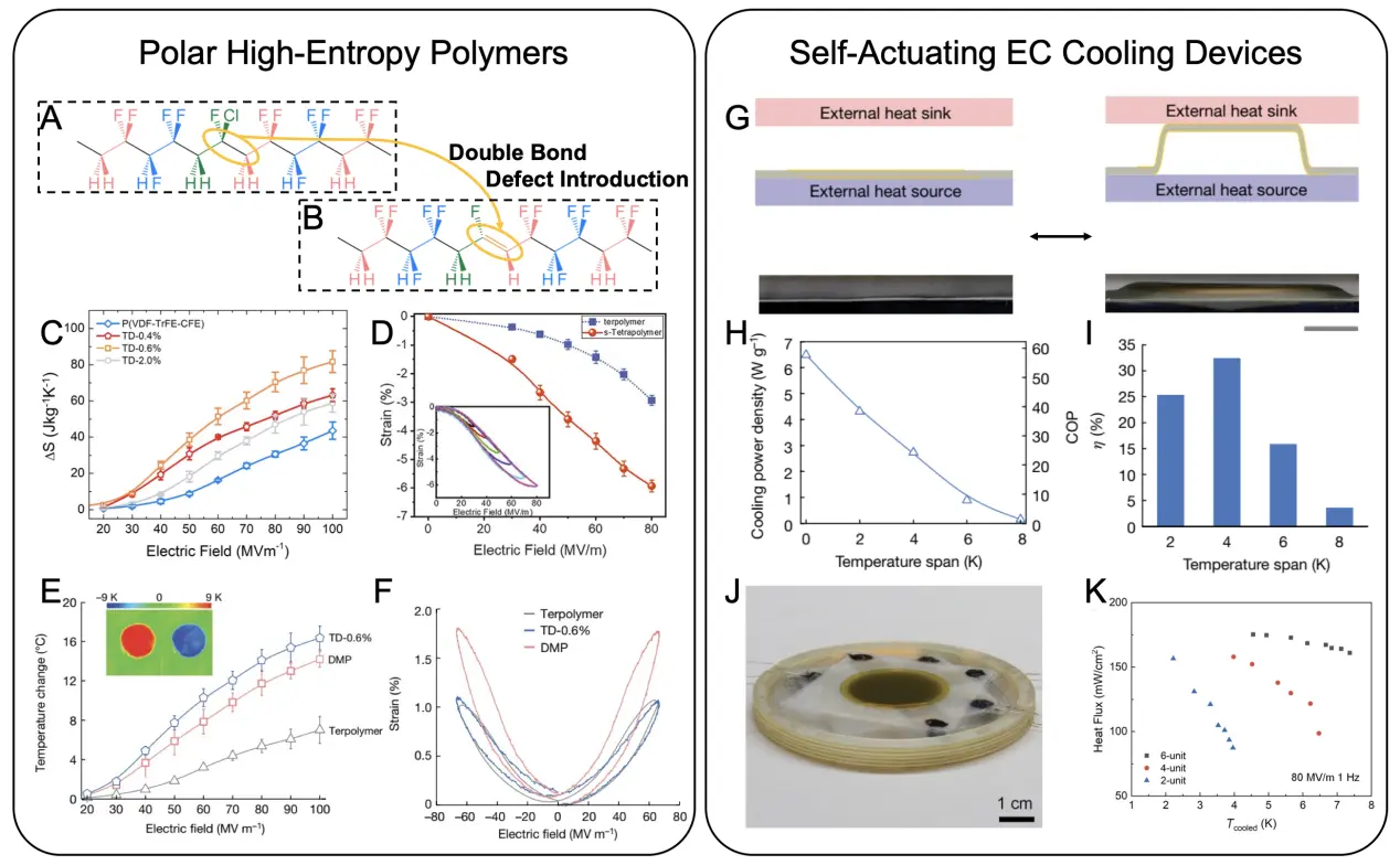
Figure 5. Polar high-entropy polymer foundations and self-actuating EC cooling devices. (A) Chemical treatment process for the terpolymer chain; (B) Introduction of double bond defects; (C) Electric field-induced changes in the entropies of PHEPs, showing greatly increased values. Republished with permission from[88]; (D) Electric field-induced strains of PHEPs with enhanced responses. Republished with permission from[90]; (E) Fine-tuned DMP exhibiting enhanced ECEs; (F) Increased field-induced strain of the fine-tuned DMP. Republished with permission from[9]; (G) Working principle of the self-actuating EC cooling device (scale bar: 5 mm). Republished with permission from[9]; (H) Cooling power densities and corresponding COPs of the self-actuating EC cooling device for different working temperature spans. Republished with permission from[9]; (I) Thermodynamic efficiencies of the self-actuating EC cooling device under different working temperature spans. Republished with permission from[9]; (J) Self-actuating EC cooling device with six PVDF-based polymer layers (scale bar: 1 mm). Republished with permission from[96]; (K) Heat flux of the six-layer EC cooling device for different working temperature spans. Republished with permission from[96]. EC: electrocaloric; PHEP: polar high-entropy polymer; DMP: defect-modified polymer; ECE: electrocaloric effect; COP: coefficient of performance; PVDF: poly(vinylidene fluoride)
Combining these significantly enhanced EC and EM properties, Chen et al. designed a self-actuated electrocaloric polymer heat pump[95]. Building on this work, Han et al. in 2024 further fine-tuned the ratio of double-bond defect ratio to 0.8%, developing a double-bond modified polymer (DMP) with both a high electric field induced entropy change (9 K @ 66.7 MV·m-1, Figure 5E) and large electric field induced strains (1.9% @ 66.7 MV·m-1, Figure 5F)[9]. Based on this DMP, the first self-oscillating polymeric refrigerator was fabricated, as shown in Figure 5G. This thin-film refrigerator is powered solely by an applied voltage, without any additional driving components. In both heat pump and cooling modes, the device provided a 4-K temperature span between the hot and cold ends at 66.7 MV·m-1. Owing to its lightweight structure and lack of additional power-supplying equipment, the device achieved the highest cooling power density of 6.5 W·g-1 among all polymeric refrigerators reported to date, corresponding to a COP of approximately 58 (Figure 5H). The thermodynamic efficiency (η) of the self-actuating device exceeded 32% with a 4-K working temperature span (Figure 5I). Notably, the cooling power density gradually decreased with increasing working temperature span, yet the device could provide cooling capacities over an 8-K working span at 66.7 MV·m-1, in excellent agreement with the results of the entropy change test. However, such a single-stage cooling device cannot provide cooling power for a working temperature exceeding ΔTad (9 K @ 66.7 MV·m-1). Cascading and integration are therefore essential for expanding the working temperature span, as further demonstrated by Wu et al. (Figure 5J,K)[96]. Using the terpolymer P(VDF-TrFE-CFE) as the solid-state refrigerant, the 6-unit self-actuating heat pump delivered a maximum specific cooling power of 1.52 W·g-1 at 80 MV·m-1 and 1 Hz, which is considerably lower than the 6.5 W·g-1 achieved by the DMP-based device. Nevertheless, the device cooled to 8.8 K below ambient temperature in 30 s at 80 MV·m-1, which is only approximately twice the value of ΔTad (~4.42 K). These results indicate that there remains substantial room for further optimization of solid-solid heat transfer in this device.
7. Testing Procedures for Determining the Cooling Performance of the EC Cooling Devices
Standardized testing procedures and well-defined performance parameters are essential for reliably assessing and comparing the cooling performance of EC devices. Key parameters for EC cooling devices include the cooling TSpan under adiabatic conditions, the cooling power (CP) and cooling power density (CPD) under fixed cold and hot end temperatures (i.e., operating temperature spans), and the COP, and η under fixed operating temperature span conditions.
The TSpan test results of an EC cooling device represent the most direct parameter for evaluating its cooling performance, reflecting the device’s capacity under zero-load conditions. This parameter comprehensively accounts for heat leakage between the device and the environment, as well as operational factors such as the the thermal variation of the EC material with insulation, irreversible losses, and operating frequency, etc. To ensure that TSpan approaches the value achievable under adiabatic conditions, thermo-insulation materials, such as thermal cotton or aerogels, are commonly used to wrap components, including pipes, during testing to minimize environmental heat leakage. The TSpan data reported for EC cooling devices in recent years are summarized in Figure 6A. Over the past 30 years, the achievable TSpan of EC devices has increased nearly fourfold due to optimized device structure design. A widely employed method to enhance TSpan is to increase the length of the EC working body, as this promotes the AER process within the device and reduces heat leakage to the surrounding environment. Simulations of the AER device (Figure 6B) intuitively show that TSpan increases significantly with the length of the EC working body. However, as more material is added, the achievable TSpan increases, indicating that TSpan becomes influenced by the amount of material and cannot serve as a standardize measure of the system’s true cooling capacity.
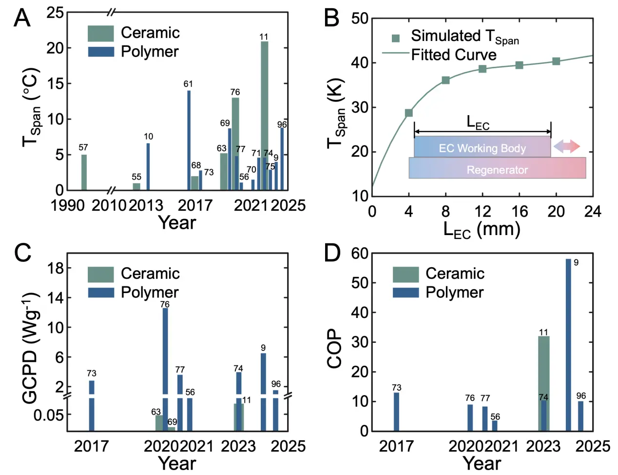
Figure 6. Cooling abilities of reported EC cooling devices. (A) TSpan values of various EC cooling devices with ceramic and polymeric refrigerants; (B) Increase in the TSpan of the EC cooling device comes larger with increased EC working body lengths; (C) GCPD of EC cooling devices with ceramic and polymeric refrigerants, calculated considering only the mass of the effective EC working body; (D) COP of EC cooling devices with ceramic and polymeric refrigerants, where the operating TSpan varies across the different cases. EC: electrocaloric; TSpan: temperature span; GCPD: general cooling power density; COP: coefficient of performance.
The gravimetric cooling power density (GCPD) provides a more precise measure of the actual performance of the EC cooling device during the cooling process. It can be calculated using the following equation:
Where CP represents the cooling power of the device and mRef represents the mass of the totally employed solid-state refrigerant. The GCPDs of various EC cooling devices reported in recent years are summarized in Figure 6C. Devices employing polymeric refrigerants exhibit significantly higher GCPD values than those using ceramic refrigerants. This is partly because polymers have lower mass and partly because the effective cooling capacity generated by ceramic materials is often dissipated in the heat recovery fluid, making efficient transfer to the cold end more challenging.
The COP is a key indicator for measuring the energy efficiency of EC cooling devices[97]. It can be calculated using the following equation:
Where WConsume is the total energy consumed by the EC cooling device. The COP data of EC cooling devices reported in recent years are summarized in Figure 6D. The self-driven device reported in 2024 achieved the highest COP (58) to date. However, this COP was measured at a zero-temperature span, reflecting only the material’s efficiency and not the device’s overall energy efficiency, since the theoretical COP limit at this temperature span is infinite. Furthermore, as shown in Figure 6C,D, the GCPD and COP data of various devices were measured at different operating temperature spans. From an engineering thermophysical perspective, GCPD and COP values are only comparable when the operating temperature span is constrained. Therefore, the establishment of an enthalpy difference platform to constrain the cooling operating temperature span is crucial for evaluating the cooling performance of EC cooling devices.
8. Enthalpy Difference Platform for Measuring Cooling Ability of EC Cooling Devices
Establishing an enthalpy difference platform is essential for accurately characterizing the cooling performance of EC devices and for providing a unified basis to comparing different system designs. Similar to traditional enthalpy difference laboratories widely used for air conditioners operating with liquid refrigerants (Figure 7A)[98-100], an enthalpy difference platform can be designed for EC cooling systems (Figure 7B). When testing the CP (or CPD) of a device, accurately controlling the effective operating temperature span between the heat sink (THeatSink) and the heat source (THeatSink) is crucial, as illustrated in Figure 7C. In this context, the heat compensation method is commonly used to measure cooling power. For example, in the 2023 study by Li et al.[36], with THeatSource and THeatSink controlled by PID, the cold end did not directly contact the object being cooled. Instead, a heater was integrated into the fluid pipeline to compensate for the cooling capacity generated by the device. Thermocouples continuously monitored the cold end temperature, forming a feedback loop. By measuring the heater’s voltage and current, the CP of the device can be calculated.
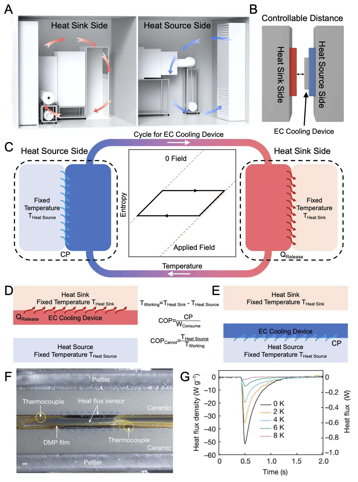
Figure 7. Experimental settings for measuring the cooling power, COP, and other relative parameters of the EC cooling devices. (A) Enthalpy difference laboratory used for traditional air conditioners; (B) Enthalpy difference platform designed for EC cooling devices; (C) Heat transfer cycle run by EC devices, regulated by the thermodynamics of the solid-state refrigerant, with temperatures of the heat source and heat sink fixed to obtain the cooling power of the EC devices; (D) Heat transfer process for EC cooling devices with the solid-state refrigerant contacting the heat sink; (E) Heat transfer process for EC cooling devices with the solid-state refrigerant contacting the heat source; (F) Experimental setup for measuring heat flux signals; (G) Heat flux results obtained under various working temperature spans (scale bar: 1 mm). Republished with permission from[9]. EC: electrocaloric; COP: coefficient of performance.
Specifically, for EC cooling devices such as self-actuating and electrostatically driven devices in which solid-state refrigerants alternately contact the heat sources and heat sinks, a one-dimensional heat transfer enthalpy difference platform can be constructed to evaluate their cooling capacity, as shown in Figure 7D,E. For instance, in a 2024 study on self-actuating cooling devices[9], Han et al. built such a one-dimensional heat transfer enthalpy difference test setup, where the heat sink and heat source temperatures were controlled using semiconductor cooling plates and monitored with thermocouples to ensure test accuracy, as shown in Figure 7F. Based on the established operating temperature span, the CP of the device could be accurately measured using heat flux sensors.
Where qRefri represents the time-dependent cooling power signals.
Under ideal conditions, when the cooling capacity generated by the solid-state refrigerant is fully transferred to the cooled end, the CP is equal to the cooling capacity of the solid-state refrigerant, expressed as follows:
Where cRef is the specific heat capacity of the solid-state refrigerant. However, in the device, owing to various losses, the CP is less than the ideal CP[101], as expressed follows:
Where LossTSpan is caused by the operating temperature span between the hot and cold ends, LossContact is caused by the thermal resistance between various interfaces, LossLeakage represents the thermal loss between the EC cooling device and the environment, and LossMedium is caused by the heat dissipation inside the heat transfer medium. Thus, under a fixed operating temperature span, reducing the interface thermal resistance[102], minimizing heat leakage between the device and the environment, and employing a heat transfer medium with high thermal conductivity[103] are crucial for maximizing the CP.
According to the laws of thermodynamic, as the operating temperature span of the device increases, its cooling power gradually decreases, as shown in Figure 7G[9]. At an operating temperature span of zero, the device delivers the maximum CP, corresponding to the highest CPD and COP. When the operating temperature span reaches the device’s adiabatic temperature change while accounting for active heat regeneration (ΔTad for single-stage devices), the device loses its cooling capability, and the corresponding COP is zero. Notably, according to the second law of thermodynamics, at a zero operating temperature span, the device’s Carnot COP is infinite. Therefore, under this condition, no information regarding the device’s efficiency can be inferred, and only the maximum cooling capacity of the device can be reported.
9. Energy Consumption Testing and Efficiency Evaluations
Simultaneously measuring energy consumption and cooling power under varying temperature spans is essential for accurately evaluating the efficiency of EC cooling devices. The device’s overall energy consumption can be calculated using the following formula.
In the formula, T is the operating period of the EC device, and QElec In and QElec Out are the energy input to and energy output from the solid-state refrigerant, respectively, in one period. ξ is the charge recovery coefficient. WMech and WCont are the consumed mechanical power and electric power, respectively, to control the operation of the EC device.
A leakage current circuit can be implemented to measure the energy input to and output from the solid-state refrigerant. Building on this, integrating a charge recovery circuit can substantially reduce the electrical energy losses associated with the refrigeration cycle. Charge recovery is a key factor that can significantly enhance the device’s COP, reduce net energy consumption, and enhance overall energy efficiency. In 2018, Defay et al. reported a charge recovery circuit that recovered 65% of the energy in an EC device containing 24 MLCCs, subsequently increasing the COP by a factor of 2.9[104]. More recently, Mönch et al. achieved an impressive energy recovery ratio exceeding 99.7% in lead magnesium niobite (PMN) MLCCs with an applied offset field and proposed a GaN/Si-hybrid DC-DC circuit[105]. Charge recovery is crucial because it can greatly increase the device’s COP, reduce net energy consumption, and improve energy utilization. The benefits of charge recovery are clearly demonstrated: for example, Li et al. achieved a COP of 32 at 4.7 K temperature span with 100% energy recovery in their double loop-based cooling device employing PST MLCCs, which is ten times higher than the COP without energy recovery (3.2)[11].
Based on energy consumption measurements, the COP and the corresponding thermodynamic efficiency can be further calculated using the following formula for a given temperature span.
10. Summary of the Cooling Capabilities of the EC Devices
The capabilities of recently reported EC devices are summarized in Table 1. The Tspan listed represents the maximum temperature span the device can achieve,, under which the CP is zero. As outlined in the testing procedures, the performance metrics of a refrigerator (CP, CPD, COP, and η), are meaningful only when the temperature spans between the heat source and heat sink, across which the refrigerator is transferring heat, are clearly defined. In future reports on EC devices, authors are encouraged to identify the temperature spans under which the device was evaluated.
Table 1. Cooling abilities of EC cooling devices employing various EC materials in different operating modes.
| Categories of EC Refrigerators | Material | TSpan (K) | GCPD (Wg-1) | VCPD (Wcm-3) | Working Temperature Span (K) | COP | Year | Ref |
| Liquidic Heat Transfer Medium | Ceramic | 5 | not given | not given | not given | not given | 1992 | [57] |
| Single-Stage Device, Mechanically Driven | Ceramic | 1 | not given | not given | not given | not given | 2012 | [55] |
| AER, Solid Regenerator | Polymer | 6.6 | not given | not given | not given | not given | 2013 | [10] |
| AER, Solid Regenerator | Ceramic | 2 | not given | not given | not given | not given | 2017 | [61] |
| AER, Air Regenerator | Polymer | 14 | not given | not given | not given | not given | 2017 | [68] |
| EA Driving Device | Polymer | 2.8 | 2.8 | 0.024 | 1.4 | 13 | 2017 | [70,73] |
| AER, Solid Regenerator | Ceramic | 5.2 | 0.047 | 0.028 | not given | 0.155 | 2020 | [63,70] |
| AER, Liquid Regenerator | Ceramic | 13 | 0.012 | 0.061 | not given | not given | 2020 | [69,70] |
| EA Driving Device | Polymer | 8.7 | 12.58 | 0.031 | 2.7 | 9 | 2020 | [70,76] |
| EA Driving Device | Polymer | 4.8 | 3.6 | 0.024 | not given | 6.8 | 2021 | [70,77] |
| 2.4 | 0.016 | not given | 8.3 | |||||
| Single-stage Device, Electromagnetic Force Driven | Polymer | 1.1 | 0.96 | not given | not given | 3.6 | 2021 | [56] |
| Liquidic Heat Transfer Medium | Polymer | 1.5 | not given | 0.7021 | not given | not given | 2022 | [70] |
| AER, Liquid Regenerator | Ceramic | 20.9 | 0.081 | 0.21 | 2.1 | not given | 2023 | [11] |
| 0.05 | 0.13 | 4.7 | 32 | |||||
| Liquidic Heat Transfer Medium | Polymer | 4.6 | not given | not given | not given | not given | 2023 | [71] |
| EA Driving Device | Polymer | 4.6 | 3.95 | 0.017 | not given | 10.4 | 2023 | [74] |
| EA Driving Device | Polymer | 2.9 | not given | 0.0929 | not given | not given | 2023 | [75] |
| Self-Actuating Device | Polymer | 4 | 6.5 | 11.7 | 0 | 58 | 2024 | [9] |
| 2.7 | 4.9 | 4 | 24 | |||||
| Self-Actuating Device | Polymer | 8.8 | 1.52 | not given | 7.4 | 10.1 | 2024 | [96] |
EC: electrocaloric; TSpan: temperature span; GCPD: general cooling power density; COP: coefficient of performance; VCPD: volumetric cooling power density; AER: active electrocaloric regenerative; EA: electrostatic actuation.
Notably, CPD is categorized into GCPD and volumetric cooling power density (VCPD), which evaluate the performance of EC cooling devices per unit mass and per unit volume, respectively. The VCPD can be calculated using the following formula:
When calculating the GCPD, only the mass of the solid-state refrigerant () is typically considered. In contrast, VCPD is calculated based on the total device volume (VDev), excluding components such as pumps, tubing, and electrical control[70]. In practice, to more accurately assess a device’s cooling capacity, the entire device volume, including all internal components, should be taken into account.
As summarized in Table 1, one of the major limitations of current EC cooling devices is their relatively small TSpan, which poses a significant challenge for practical applications, particularly when compared with conventional VCR systems that typically achieve much larger temperature differences. This intrinsic limitation restricts the standalone use of EC cooling in scenarios requiring wide operating ranges. Several strategies have been proposed to address this issue. Among them, the AER cycle has shown particular promise in extending the effective TSpan by sequentially regenerating heat between multiple EC elements. In parallel, advances in material engineering, such as optimizing phase transition characteristics, reducing thermal hysteresis, and enhancing ECE, offer potential pathways to increase the intrinsic temperature change of EC materials. Furthermore, hybrid cooling architectures that combine EC with complementary thermal management approaches (e.g., thermoelectrics, vapor chambers, or passive radiative cooling) may also help overcome the TSpan limitation, enabling EC devices to play a critical role in compact and energy-efficient refrigeration systems.
11. Outlook and Future Challenges
While EC cooling devices hold great promise for compact and environmentally friendly refrigeration, several challenges remain for real-world deployment. Beyond the material and engineering issues discussed earlier, the feasibility of applying the very high electric fields required for electrocaloric operation represents a critical concern. Although large electric fields are essential to induce significant ECE, they may also accelerate dielectric breakdown, mechanical fatigue, and interfacial degradation, thereby limiting device longevity. Encouragingly, recent advances in multilayer capacitors, thin-film architectures, and polymer composites have demonstrated the ability to sustain high fields with improved breakdown strength and reliability. Nonetheless, ensuring stable operation under prolonged cyclic electrical and mechanical stress remains a formidable challenge. Potential engineering strategies, including optimized electrode configurations, advanced dielectric designs, and field concentration management, may help mitigate these limitations. Addressing the high-field requirement in a practical and scalable manner is vital for bridging the gap between laboratory demonstrations and commercially viable EC cooling systems.
From a materials perspective, practical EC devices require advances in EC materials, not only in terms of ECE[106], but also with respect to electrical, mechanical, and thermal properties[83,107-109]. A quality factor has been proposed for evaluating EC nanocomposites by considering their thermal conductivities, entropy changes, temperature changes, breakdown possibilities, hysteresis, and weights[103]. Although a universal figure of merit for all EC working bodies would be highly desired, the development of EC materials is closely tied to specific application scenarios. It remains premature to determine which EC material is superior without identifying the optimal application. When a significant amount of EC material is integrated into a high-quality working body, both ceramics and polymers can serve as effective cooling cores in current and future applications.
For a given material, the most straightforward strategy for improving the refrigeration performance of an EC device is to increase the volume of the EC working body. EC working bodies are commonly fabricated by integrating EC-active sheets into multilayer capacitors (MLCs) for both ceramics[110] and polymers[111]. Unlike MLCCs designed for commercial capacitors, MLCCs intended for EC devices must minimize inactive volume and adopt a thin, flat-panel geometry to enhance heat exchange and enable high cycling frequencies[112]. For example, for an EC working body with a thermal conductivity of 5 W·m-1·K-1 and an operating frequency of 1 Hz in an AER cycle, the thermal diffusion length is approximately 0.63 mm[113]. Such a thin geometry may result in shape deformation or even breakage if conventional commercial MLCC fabrication processes are used. Therefore, customized manufacturing processes are necessary to produce high-quality ceramic working bodies.
The thermal conductivity of a material is a critical factor for the performance of an EC device[114]. Interestingly, although a giant ECE can be achieved by inducing polar disorder, high thermal conductivity typically requires an ordered lattice structure. The ordered lattice, however, may conflict with the goal of attaining polar randomness. For example, it has been reported that simply incorporating high-thermal-conductivity fillers, such as boron nitride nanosheets, into EC polymers can reduce the ECE of the resulting nanocomposites[103]. Therefore, effectively decoupling the ordered lattice from the disordered polar entities is essential for designing nanocomposites that exhibit both a large ECE and high thermal conductivity.
Engineering hurdles include ensuring device reliability and longevity under cyclic high electric fields and mechanical stress, as well as developing efficient heat regeneration schemes and robust packaging. The fabrication of EC-active MLPCs could be facilitated by roll-to-roll (R2R) manufacturing techniques[115,116]. Looking ahead, the use of EC polymers with exceptional mechanical moduli would be advantageous for easier handling and processing of MLPCs[117]. The recent discovery of elastic ferroelectric polymers[118] has further stimulated research on elastic EC polymers for wearable cooling devices. Their large elastic strain (up to 125%) provides excellent mechanical stability under varying external stresses and ensures thorough mechanical contact with convoluted, soft surfaces in wearables devices.
On the commercialization front, scalable manufacturing, cost-effectiveness, and integration with existing thermal management systems are critical. Fabricating EC polymers into fibers[119], tubing[70,71], and fabric (likely in the near future) will have a significant impact on the development of wearable personal cooling systems. Such wearables could enable individual air conditioning powered by lightweight, efficient, and compact energy source, providing clear advantages over conventional refrigeration technologies. For skin comfort, a TSpan of approximately 4 K is sufficient[120,121]. Although this is much lower than the ~40 K TSpan required for household air conditioning, it is already achievable with current EC materials. Thus, enhancing both the overall cooling power of EC devices and the intrinsic properties of EC material remains an urgent priority.
Importantly, to better support system designers, EC cooling should also be considered within hybrid architectures that integrate complementary mechanisms such as passive radiative cooling, thermoelectrics, vapor chambers, and evaporative or adsorptive cooling. Such hybridization can significantly improve overall efficiency and expand the range of potential applications. EC cooling is particularly effective when rapid, localized, and switchable cooling is required in compact systems, for example, wearable electronics, on-chip hot-spot management, or portable solid-state refrigeration, while complementary methods handle bulk or long-term heat transport. Coordinated progress across these fronts will be essential for advancing EC technology from laboratory demonstrations to impactful applications.
12. Conclusion
In conclusion, EC refrigeration presents a highly promising pathway for next-generation cooling technologies, offering superior energy efficiency, zero direct carbon emissions, and compact device architectures. Over the past two decades, substantial progress has been achieved in the development of EC cooling devices with increasing performances, delivering clear advantages in both energy conservation and environmental sustainability. Through analysis of the operational principles and thermodynamic cycles of solid-state refrigerants, we emphasized that testing conditions should be standardized to ensure accurate evaluation of device performance, for which the establishment of an enthalpy difference platform is crucial. Furthermore, we highlighted the broad application potential of EC cooling. By overcoming current material and engineering challenges, EC refrigeration can progress toward industrial deployment, enabling future refrigeration systems that are not only more efficient but also environmentally sustainable.
Acknowledgments
Xiaoshi Qian gratefully acknowledges the support of the Shanghai Jiao Tong University 2030 Initiative, the SiYuan Scholar Program, the Student Innovation Center, and the National Facility for Translational Medicine (Shanghai), as well as the financial support provided by the National Key R & D Program of China (2020YFA0711500), the National Natural Science Foundation of China (52506020, T2488302, 52076127), the China National Postdoctoral Program for Innovative Talents (BX20250273), and the Shanghai Postdoctoral Excellence Program (2024312).
Authors contribution
Han D, Zhao Y: Writing-original draft, writing-review & editing.
Qian X: Conceptualization, writing-review & editing, funding acquisition; resources, supervision.
Conflicts of interest
The authors declare no conflicts of interest.
Ethical approval
Not applicable.
Consent to participate
Not applicable.
Consent for publication
Not applicable.
Availability of data and materials
Not applicable.
Funding
This work was supported by the National Key R&D Program of China (2020YFA0711500), National Natural Science Foundation of China (52506020, T2488302, 52076127), China National Postdoctoral Program for Innovative Talents (BX20250273), Shanghai Post-doctoral Excellence Program (2024312).
Copyright
© The Author(s) 2025.
References
-
1. Qian X. Pumping into a cool future: electrocaloric materials for zero-carbon refrigeration. Front Energy. 2022;16:19-22.[DOI]
-
2. Franco V, Blázquez JS, Ipus JJ, Law JY, Moreno-Ramírez LM, Conde A. Magnetocaloric effect: From materials research to refrigeration devices. Prog Mater Sci. 2018;93:112-232.[DOI]
-
3. Lin Y, Wang J, Dai W, Qiao K, Zhou H, Zhao T, et al. A full solid-state conceptual magnetocaloric refrigerator based on hybrid regeneration. Innovation. 2024;5(4):100645.[DOI]
-
4. Johra H, Filonenko K, Heiselberg P, Veje C, Dall’Olio S, Engelbrecht K, et al. Integration of a magnetocaloric heat pump in an energy flexible residential building. Renew Energy. 2019;136:115-126.[DOI]
-
5. Qian S, Catalini D, Muehlbauer J, Liu B, Mevada H, Hou H, et al. High-performance multimode elastocaloric cooling system. Science. 2023;380(6646):722-727.[DOI]
-
6. Zhou G, Zhang L, Li Z, Hua P, Sun Q, Yao S. Achieving kilowatt-scale elastocaloric cooling by a multi-cell architecture. Nature. 2025;639:87-92.[DOI]
-
7. Tušek J, Engelbrecht K, Eriksen D, Dall’Olio S, Tušek J, Pryds N. A regenerative elastocaloric heat pump. Nat Energy. 2016;1:16134.[DOI]
-
8. Zhang S, Yang Q, Li C, Fu Y, Zhang H, Ye Z, et al. Solid-state cooling by elastocaloric polymer with uniform chain-lengths. Nat Commun. 2022;13:9.[DOI]
-
9. Han D, Zhang Y, Huang C, Zheng S, Wu D, Li Q, et al. Self-oscillating polymeric refrigerator with high energy efficiency. Nature. 2024;629:1041-1046.[DOI]
-
10. Gu H, Qian X, Li X, Craven B, Zhu W, Cheng A, et al. A chip scale electrocaloric effect based cooling device. Appl Phys Lett. 2013;102(12):122904.[DOI]
-
11. Li J, Torelló A, Kovacova V, Prah U, Aravindhan A, Granzow T, et al. High cooling performance in a double-loop electrocaloric heat pump. Science. 2023;382(6672):801-805.[DOI]
-
12. Aznar A, Lloveras P, Romanini M, Barrio M, Tamarit JL, Cazorla C, et al. Giant barocaloric effects over a wide temperature range in superionic conductor AgI. Nat Commun. 2017;8:1851.[DOI]
-
13. Li B, Kawakita Y, Ohira-Kawamura S, Sugahara T, Wang H, Wang J, et al. Colossal barocaloric effects in plastic crystals. Nature. 2019;567:506-510.[DOI]
-
14. Lloveras P, Aznar A, Barrio M, Negrier P, Popescu C, Planes A, et al. Colossal barocaloric effects near room temperature in plastic crystals of neopentylglycol. Nat Commun. 2019;10:1803.[DOI]
-
15. Russ B, Glaudell A, Urban JJ, Chabinyc ML, Segalman RA. Organic thermoelectric materials for energy harvesting and temperature control. Nat Rev Mater. 2016;1:16050.[DOI]
-
16. Tritt TM. Thermoelectric phenomena, materials, and applications. Annu Rev Mater Res. 2011;41:433-448.[DOI]
-
17. Kobeco P, Kurtchatov IV. Dielectric properties of Rochelle salt crystal. Z Phys. 1930;66(3-4):192-205.
-
18. Mischenko AS, Zhang Q, Scott JF, Whatmore RW, Mathur ND. Giant electrocaloric effect in thin-film PbZr0.95Ti0.05O3. Science. 2006;311(5765):1270-1271.[DOI]
-
19. Neese B, Chu B, Lu SG, Wang Y, Furman E, Zhang QM. Large electrocaloric effect in ferroelectric polymers near room temperature. Science. 2008;321(5890):821-823.[DOI]
-
20. Valant M. Electrocaloric materials for future solid-state refrigeration technologies. Prog Mater Sci. 2012;57(6):980-1009.[DOI]
-
21. Li X, Lu SG, Chen XZ, Gu H, Qian XS, Zhang QM. Pyroelectric and electrocaloric materials. Pyroelectric and electrocaloric materials. J Mater Chem C. 2013;1:23-37.[DOI]
-
22. Moya X, Stern-Taulats E, Crossley S, González-Alonso D, Kar-Narayan S, Planes A, et al. Giant electrocaloric strength in single-crystal BaTiO3. Adv Mater. 2013;25(9):1360-1365.[DOI]
-
23. Liu Y, Wei J, Janolin PE, Infante IC, Lou X, Dkhil B. Giant room-temperature barocaloric effect and pressure-mediated electrocaloric effect in BaTiO3 single crystal. Appl Phys Lett. 2014;104(16):162904.[DOI]
-
24. Qiu JH, Zhao TX, Chen ZH, Wang XQ, Yuan NY, Ding JN. Electrocaloric effects of bulk and thin film Ba (Zr0.08Ti0.92)O3 single crystals. Physica B. 2019;552:47-51.[DOI]
-
25. Qian XS, Ye HJ, Zhang YT, Gu H, Li X, Randall CA, et al. Giant electrocaloric response over a broad temperature range in modified BaTiO3 ceramics. Adv Funct Mater. 2014;24(9):1300-1305.[DOI]
-
26. Li J, Zhang D, Qin S, Li T, Wu M, Wang D, et al. Large room-temperature electrocaloric effect in lead-free BaHfxTi1-xO3 ceramics under low electric field. Acta Mater. 2016;115:58-67.[DOI]
-
27. Qian J, Hu P, Liu C, Jiang J, Dan Z, Ma J, et al. High electrocaloric cooling power of relaxor ferroelectric BaZrxTi1-xO3 ceramics within broad temperature range. Sci Bull. 2018;63(6):356-361.[DOI]
-
28. Du F, Song Z, Xu Y, Han D, Li Q, Zheng S, et al. Multi-element B-site substituted perovskite ferroelectrics exhibit enhanced electrocaloric effect. Sci China Technol Sci. 2023;66:1119-1128.[DOI]
-
29. Hou Y, Yang L, Qian X, Zhang T, Zhang QM. Electrocaloric response near room temperature in Zr-and Sn-doped BaTiO3 systems. Phil Trans R So A. 2016;374(2074):20160055.[DOI]
-
30. Hou Y, Yang L, Qian X, Zhang T, Zhang QM. Enhanced electrocaloric effect in composition gradient bilayer thick films. Appl Phys Lett. 2016;108:133501.[DOI]
-
31. Kumar R, Singh S. Enhanced electrocaloric response and high energy-storage properties in lead-free (1-x)(K0.5Na0.5) NbO3-xSrZrO3 nanocrystalline ceramics. J Alloys Compd. 2018;764:289-294.[DOI]
-
32. Ye HJ, Qian XS, Jeong DY, Zhang S, Zhou Y, Shao WZ, et al. Giant electrocaloric effect in BaZr0.2Ti0.8O3 thick film. Appl Phys Lett. 2014;105:152908.[DOI]
-
33. Lu SG, Rožič B, Zhang QM, Kutnjak Z, Neese B. Enhanced electrocaloric effect in ferroelectric poly(vinylidene-fluoride/trifluoroethylene) 55/45 mol % copolymer at ferroelectric-paraelectric transition. Appl Phys Lett. 2011;98(12):122906.[DOI]
-
34. Li X, Qian XS, Gu H, Chen X, Lu SG, Lin M, et al. Giant electrocaloric effect in ferroelectric poly(vinylidenefluoride-trifluoroethylene) copolymers near a first-order ferroelectric transition. Appl Phys Lett. 2012;101(13):132903.[DOI]
-
35. Bobnar V, Li X, Casar G, Eršte A, Glinšek S, Qian X, et al. Tailoring electrically induced properties by stretching relaxor polymer films. J Appl Phys. 2012;111:083515.[DOI]
-
36. Moreira RL. Electrocaloric effect in γ-Irradiated P(VDF-TrFE) copolymers with relaxor features. Ferroelectrics. 2013;446(1):1-8.[DOI]
-
37. Chen XZ, Qian XS, Li X, Lu SG, Gu HM, Lin M, et al. Enhanced electrocaloric effect in poly(vinylidene fluoride-trifluoroethylene)-based terpolymer/copolymer blends. Appl Phys Lett. 2012;100(22):222902.[DOI]
-
38. Qian X, Yang T, Zhang T, Chen LQ, Zhang QM. Anomalous negative electrocaloric effect in a relaxor/normal ferroelectric polymer blend with controlled nano-and meso-dipolar couplings. Appl Phys Lett. 2016;108:142902.[DOI]
-
39. Zhang G, Fan B, Zhao P, Hu Z, Liu Y, Liu F, et al. Ferroelectric polymer nanocomposites with complementary nanostructured fillers for electrocaloric cooling with high power density and great efficiency. ACS Appl Energy Mater. 2018;1(3):1344-1354.[DOI]
-
40. Cai Y, Li Q, Du F, Feng J, Han D, Zheng S, et al. Polymeric nanocomposites for electrocaloric refrigeration. Front Energy. 2023;17:450-462.[DOI]
-
41. Du F, Yang S, Yao T, Han D, Li Q, Zheng S, et al. Infinitesimal amount of perovskite quantum dots enhances electrocaloric cooling performances in diluted nanocomposites. Joule. 2025;9(9):102057.[DOI]
-
42. Zhang G, Weng L, Hu Z, Liu Y, Bao R, Zhao P, et al. Nanoconfinement‐induced giant electrocaloric effect in ferroelectric polymer nanowire array integrated with aluminum oxide membrane to exhibit record cooling power density. Adv Mater. 2019;31(8):1806642.[DOI]
-
43. Qian XS, Lu SG, Li X, Gu H, Chien LC, Zhang Q. Large electrocaloric effect in a dielectric liquid possessing a large dielectric anisotropy near the isotropic–nematic transition. Adv Mater. 2013;23, 2894-2898:[DOI]
-
44. Trček M, Lavrič M, Cordoyiannis G, Zalar B, Rožič B, Kralj S, et al. Electrocaloric and elastocaloric effects in soft materials. Phil Trans R Soc A. 2016;374:20150301.[DOI]
-
45. Dobovišek A, Ambrožič M, Kutnjak Z, Kralj S. Liquid crystal based active electrocaloric regenerator. Heliyon. 2023;9(3):e14035.[DOI]
-
46. Shi J, Han D, Li Z, Yang L, Lu SG, Zhong Z, et al. Electrocaloric cooling materials and devices for zero-global-warming-potential, high-efficiency refrigeration. Joule. 2019;3(5):1200-1225.[DOI]
-
47. Chen X, Shvartsman VV, Lupascu DC, Zhang QM. Electrocaloric cooling—From materials to devices. J Appl Phys. 2022;132:240901.[DOI]
-
48. Abas N, Kalair AR, Khan N, Haider A, Saleem Z, Saleem MS. Natural and synthetic refrigerants, global warming: a review. Renew Sustain Energy Rev. 2018;90:557-569.[DOI]
-
49. Schwartz DE. Thermodynamic cycles and electrical charge recovery in high-efficiency electrocaloric cooling systems. Int J Refrig. 2021;131:970-979.[DOI]
-
50. Greco A, Masselli C. Electrocaloric cooling: a review of the thermodynamic cycles, materials, models, and devices. Magnetochemistry. 2020;6(4):67.[DOI]
-
51. Yu B, Yang J, Wang D, Shi J, Chen J. An updated review of recent advances on modified technologies in transcritical CO2 refrigeration cycle. Energy. 2019;189:116147.[DOI]
-
52. Shi J, Li Q, Gao T, Han D, Li Y, Chen J, et al. Numerical evaluation of a kilowatt-level rotary electrocaloric refrigeration system. Int J Refrig. 2021;121:279-288.[DOI]
-
53. Shi J, Li Q, Gao T, Han D, Li Y, Chen J, et al. Concept design and numerical evaluation of a highly efficient rotary electrocaloric refrigeration device. Appl Therm Eng. 2021;190:116806.[DOI]
-
54. Ju YS. Solid-state refrigeration based on the electrocaloric effect for electronics cooling. J Electron Packag. 2010;132(4):041004.[DOI]
-
55. Jia Y, Sungtaek Ju Y. A solid-state refrigerator based on the electrocaloric effect. Appl Phys Lett. 2012;100:242901.[DOI]
-
56. Kang X, Jia S, Peng J, Yu H, Zhou X. Electromagnetic-driven electrocaloric cooling device based on ternary ferroelectric composites. Compos Part B Eng. 2021;227:109391.[DOI]
-
57. Sinyavsky YV, Brodyansky VM. Experimental testing of electrocaloric cooling with transparent ferroelectric ceramic as a working body. Ferroelectrics. 1992;131(1):321-325.[DOI]
-
58. Gu H, Li X, Lu SG, Lin M, Qian X, Cheng JP, et al. Compact cooling devices based on giant electrocaloric effect dielectrics. In: ASME 2012 Heat Transfer Summer Conference collocated with the ASME 2012 Fluids Engineering Division Summer Meeting and the ASME 2012 10th International Conference on Nanochannels, Microchannels, and Minichannels; 2012 Jul 8-12; Puerto Rico, USA. New York: ASME; 2012. p. 635-639.[DOI]
-
59. Gu H, Craven B, Qian X, Li X, Cheng A, Zhang QM. Simulation of chip-size electrocaloric refrigerator with high cooling-power density. Appl Phys Lett. 2013;102(11):112901. 10.1063/1.4796184.
-
60. Zhang T, Qian XS, Gu H, Hou Y, Zhang QM. An electrocaloric refrigerator with direct solid to solid regeneration. Appl Phys Lett. 2017;110:243503.[DOI]
-
61. Gu H, Qian XS, Ye HJ, Zhang QM. An electrocaloric refrigerator without external regenerator. Appl Phys Lett. 2014;105:162905.[DOI]
-
62. Nair B, Usui T, Crossley S, Kurdi S, Guzmán-Verri GG, Moya X, et al. Large electrocaloric effects in oxide multilayer capacitors over a wide temperature range. Nature. 2019;575:468-472.[DOI]
-
63. Wang Y, Zhang Z, Usui T, Benedict M, Hirose S, Lee J, et al. A high-performance solid-state electrocaloric cooling system. Science. 2020;370(6512):129-133.[DOI]
-
64. Aprea C, Greco A, Maiorino A, Masselli C. Solid-state refrigeration: a comparison of the energy performances of caloric materials operating in an active caloric regenerator. Energy. 2018;165:439-455.[DOI]
-
65. Plaznik U, Vrabelj M, Kutnjak Z, Malič B, Rožič B, Poredoš A, et al. Numerical modelling and experimental validation of a regenerative electrocaloric cooler. Int J Refrig. 2019;98:139-149.[DOI]
-
66. Guo D, Gao J, Yu YJ, Santhanam S, Slippey A, Fedder GK, et al. Design and modeling of a fluid-based micro-scale electrocaloric refrigeration system. Int J Heat Mass Transf. 2014;72:559-564.[DOI]
-
67. Plaznik U, Kitanovski A, Rožič B, Malič B, Uršič H, Drnovšek S, et al. Bulk relaxor ferroelectric ceramics as a working body for an electrocaloric cooling device. Appl Phys Lett. 2015;106(4):043903.[DOI]
-
68. Annapragada SR, Verma P, Sur A, Xie W. High-efficiency solid state heat pump module. Oak Ridge (TN): Oak Ridge National Laboratory; 2018 Feb. Report No.;ORNL/TM-2018/111.[DOI]
-
69. Torelló A, Lheritier P, Usui T, Nouchokgwe Y, Gérard M, Bouton O, et al. Giant temperature span in electrocaloric regenerator. Science. 2020;370(6512):125-129.[DOI]
-
70. Cui H, Zhang Q, Bo Y, Bai P, Wang M, Zhang C, et al. Flexible microfluidic electrocaloric cooling capillary tube with giant specific device cooling power density. Joule. 2022;6(1):258-268.[DOI]
-
71. Bai P, Cui H, Zhang D, Bo Y, Liu L, Ma R. A highly efficient cascade electrocaloric cooling tube with enhanced temperature change by sawtooth voltage. Next Mater. 2023;1(1):100001.[DOI]
-
72. Bradeško A, Juričić Đ, Santo Zarnik M, Malič B, Kutnjak Z, Rojac T. Coupling of the electrocaloric and electromechanical effects for solid-state refrigeration. Appl Phys Lett. 2016;109(14):143508.[DOI]
-
73. Ma R, Zhang Z, Tong K, Huber D, Kornbluh R, Ju YS et al. Highly efficient electrocaloric cooling with electrostatic actuation. Science. 2017;357(6356):1130-1134.[DOI]
-
74. Bai P, Zhang Q, Cui H, Bo Y, Zhang D, He W, et al. An active pixel‐matrix electrocaloric device for targeted and differential thermal management. Adv Mater. 2023;35(15):2209181.[DOI]
-
75. Wang Z, Bo Y, Bai P, Zhang S, Li G, Wan X, et al Self-sustaining personal all-day thermoregulatory clothing using only sunlight. Science. 2023;382(6676):1291-1296.[DOI]
-
76. Meng Y, Zhang Z, Wu H, Wu R, Wu J, Wang H, et al. A cascade electrocaloric cooling device for large temperature lift. Nat Energy. 2020;5:996-1002.[DOI]
-
77. Bo Y, Zhang Q, Cui H, Wang M, Zhang C, He W, et al. Electrostatic actuating double‐unit electrocaloric cooling device with high efficiency. Adv Energy Mater. 2021;11(13):2003771.[DOI]
-
78. Bauer F, Fousson E, Zhang QM. Recent advances in highly electrostrictive P (VDF-TrFE-CFE) terpolymers. IEEE Trans Dielectr Electr Insul. 2006;13(5):1149-1154.[DOI]
-
79. Capsal JF, Galineau J, Le MQ, Domingues Dos Santos F, Cottinet PJ. Enhanced electrostriction based on plasticized relaxor ferroelectric P (VDF‐TrFE‐CFE/CTFE) blends. J Polym Sci B Polym Phys. 2015;53(19):1368-1379.[DOI]
-
80. Lu SG, Xiong H, Wei A, Li X, Zhang Q. Electrocaloric and electrostrictive effect of polar P (VDF-TrFE-CFE) terpolymers. J Adv Dielectr. 2013;3(02):1350015.[DOI]
-
81. Chen Y, Qian J, Yu J, Guo M, Zhang Q, Jiang J, et al. An all-scale hierarchical architecture induces colossal room-temperature electrocaloric effect at ultralow electric field in polymer nanocomposites. Adv Mater. 2020;32(30):1907927.[DOI]
-
82. Chen XZ, Li X, Qian XS, Lin M, Wu S, Shen QD, et al. A nanocomposite approach to tailor electrocaloric effect in ferroelectric polymer. Polymer. 2013;54(20):5299-5302.[DOI]
-
83. Zhang G, Zhang X, Yang T, Li Q, Chen LQ, Jiang S, et al. Colossal room-temperature electrocaloric effect in ferroelectric polymer nanocomposites using nanostructured barium strontium titanates. ACS Nano. 2015;9(7):7164-7174.[DOI]
-
84. Li Q, Zhang G, Zhang X, Jiang S, Zeng Y, Wang Q. Relaxor ferroelectric-based electrocaloric polymer nanocomposites with a broad operating temperature range and high cooling energy. Adv Mater. 2015;27(13):2236-2241.[DOI]
-
85. Qian J, Peng R, Shen Z, Jiang J, Xue F, Yang T, et al. Interfacial coupling boosts giant electrocaloric effects in relaxor polymer nanocomposites: in situ characterization and phase-field simulation. Adv Mater. 2019;31(5):1801949.[DOI]
-
86. Le Goupil F, Kallitsis K, Tencé-Girault S, Pouriamanesh N, Brochon C, Cloutet E, et al. Enhanced electrocaloric response of vinylidene fluoride-based polymers via one-step molecular engineering. Adv Funct Mater. 2021;31(1):2007043.[DOI]
-
87. Tan S, Li J, Gao G, Li H, Zhang Z. Synthesis of fluoropolymer containing tunable unsaturation by a controlled dehydrochlorination of P (VDF-co-CTFE) and its curing for high performance rubber applications. J Mater Chem. 2012;22:18496-18504.
-
88. Qian X, Han D, Zheng L, Chen J, Tyagi M, Li Q, et al. High-entropy polymer produces a giant electrocaloric effect at low fields. Nature. 2021;600:664-669.[DOI]
-
89. Kang L, Han D, Hong L, Zheng L, Qian X. Statistical mechanical model of the giant electrocaloric effect in ferroelectric polymers. ACS Macro Lett. 2023;12(7):848-853.[DOI]
-
90. Chen X, Qin H, Qian X, Zhu W, Li B, Zhang B, et al. Relaxor ferroelectric polymer exhibits ultrahigh electromechanical coupling at low electric field. Science. 2022;375(6587):1418-1422.[DOI]
-
91. Uchino K. Ferroelectric devices. 2nd ed. USA: CRC Press;2009:[DOI]
-
92. Omote K, Ohigashi H, Koga K. Temperature dependence of elastic, dielectric, and piezoelectric properties of “single crystalline” films of vinylidene fluoride trifluoroethylene copolymer. J Appl Phys. 1997;81(6):2760-2769.[DOI]
-
93. Liu Y, Aziguli H, Zhang B, Xu W, Lu W, Bernholc J, et al. Ferroelectric polymers exhibiting behaviour reminiscent of a morphotropic phase boundary. Nature. 2018;562:96-100.[DOI]
-
94. Wang H, Zhang QM, Cross LE, Sykes AO. Piezoelectric, dielectric, and elastic properties of poly (vinylidene fluoride/trifluoroethylene). J Appl Phys. 1993;74(5):3394-3398.[DOI]
-
95. Chen X, Zhu W, Rattner AS, Zhang QM. A self-actuated electrocaloric polymer heat pump design exploiting the synergy of electrocaloric effect and electrostriction. J Phys Energy. 2023;5:024009.[DOI]
-
96. Wu H, Zhu Y, Yan W, Zhang S, Budiman W, Liu K, et al. A self-regenerative heat pump based on a dual-functional relaxor ferroelectric polymer. Science. 2024;386:546-551.[DOI]
-
97. Qian S, Nasuta D, Rhoads A, Wang Y, Geng Y, Hwang Y, et al. Not-in-kind cooling technologies: A quantitative comparison of refrigerants and system performance. Int J Refrig. 2016;62:177-192.[DOI]
-
98. Ye Z, Shi J, Chen J. Frosting behavior of louvered-fin and tube heat exchanger after surface treatment: experimental analysis. Appl Therm Eng. 2021;194:117066.[DOI]
-
99. Song X, Lu D, Lei Q, Wang D, Yu B, Shi J, et al. Energy and exergy analyses of a transcritical CO2 air conditioning system for an electric bus. Appl Therm Eng. 2021;190:116819.[DOI]
-
100. Sánchez D, Cabello R, Llopis R, Arauzo I, Catalán-Gil J, Torrella E. Energy performance evaluation of R1234yf, R1234ze(E), R600a, R290 and R152a as low-GWP R134a alternatives. Int J Refrig. 2017;74:269-282.[DOI]
-
101. Hou H, Qian S, Takeuchi I. Materials, physics and systems for multicaloric cooling. Nat Rev Mater. 2022;7:633-652.[DOI]
-
102. Zhou T, Zhao Y, Rao Z. Fundamental and estimation of thermal contact resistance between polymer matrix composites: a review. Int J Heat Mass Transf. 2022;189:122701.[DOI]
-
103. Han D, Du F, Zhang Y, Zheng L, Chen J, Huang X, et al. Molecular interface regulation enables order-disorder synergy in electrocaloric nanocomposites. Joule. 2023;7(9):2174-2190.[DOI]
-
104. Defay E, Faye R, Despesse G, Strozyk H, Sette D, Crossley S, et al. Enhanced electrocaloric efficiency via energy recovery. Nat Commun. 2018;9:1827.[DOI]
-
105. Moench S, Reiner R, Waltereit P, Molin C, Gebhardt S, Bach D, et al. Enhancing electrocaloric heat pump performance by over 99% efficient power converters and offset fields. IEEE Access. 2022;10:46571-46588.[DOI]
-
106. Zheng S, Du F, Zheng L, Han D, Li Q, Shi J, et al. Colossal electrocaloric effect in an interface-augmented ferroelectric polymer. Science. 2023;382(6674):1020-1026.[DOI]
-
107. Cai Y, Chen X, Han D, Li Y, Chen Y, Mai R, et al. High-entropy alloy enhances electrocaloric effect in ferroelectric polymers for magnetic-field-driven, solid-state refrigeration. Cell Rep Phys Sci. 2025;6(4):102513.[DOI]
-
108. Li Q, Wei L, Zhong N, Shi X, Han D, Zheng S, et al. Low-k nano-dielectrics facilitate electric-field induced phase transition in high-k ferroelectric polymers for sustainable electrocaloric refrigeration. Nat Commun. 2024;15:702.[DOI]
-
109. Zhang G, Li Q, Gu H, Jiang S, Han K, Gadinski M, et al. Ferroelectric polymer nanocomposites for room-temperature electrocaloric refrigeration. Adv Mater. 2015;27(8):1450-1454.[DOI]
-
110. Nouchokgwe Y, Lheritier P, Usui T, Torello A, El Moul A, Kovacova V, et al. Materials efficiency of electrocaloric lead scandium tantalate multilayer capacitors. Scr Mater. 2022;219:114873.[DOI]
-
111. Prateek , Thakur VK, Gupta RK. Recent progress on ferroelectric polymer-based nanocomposites for high energy density capacitors: synthesis, dielectric properties, and future aspects. Chem Rev. 2016;116(7):4260-4317.[DOI]
-
112. Du F, Yang T, Hao H, Li S, Xu C, Yao T, et al. Giant electrocaloric effect in high-polar-entropy perovskite oxides. Nature. 2025;640:924-930.[DOI]
-
113. Gu H. Chip-scale cooling devices based on electrocaloric effect [dissertation]. USA: The Pennsylvania State University; 2014.
-
114. Li MD, Shen XQ, Chen X, Gan JM, Wang F, Li J, et al. Thermal management of chips by a device prototype using synergistic effects of 3-D heat-conductive network and electrocaloric refrigeration. Nat Commun. 2022;13:5849.[DOI]
-
115. Yang M, Li H, Wang J, Shi W, Zhang Q, Xing H, et al. Roll-to-roll fabricated polymer composites filled with subnanosheets exhibiting high energy density and cyclic stability at 200 °C. Nat Energy. 2024;9:143-153.[DOI]
-
116. Qian X, Wu S, Furman E, Zhang QM, Su J. Ferroelectric polymers as multifunctional electroactive materials: recent advances, potential, and challenges. MRS Commun. 2015;5:115-129.[DOI]
-
117. Qian X, Chen X, Zhu L, Zhang QM. Fluoropolymer ferroelectrics: Multifunctional platform for polar-structured energy conversion. Science. 2023;380(6645):eadg0902.[DOI]
-
118. Gao L, Hu BL, Wang L, Cao J, He R, Zhang F, et al. Intrinsically elastic polymer ferroelectric by precise slight cross-linking. Science. 2023;381(6657):540-544.[DOI]
-
119. Wang H, Meng Y, Zhang Z, Gao M, Peng Z, He H, et al. Self-actuating electrocaloric cooling fibers. Adv Funct Mater. 2020;10(12):1903902.[DOI]
-
120. Yang H, Deng Y, Cao B, Zhu Y. Study on the local and overall thermal perceptions under nonuniform thermal exposure using a cooling chair. Build Environ. 2020;176:106864.[DOI]
-
121. Luo M, Arens E, Zhang H, Ghahramani A, Wang Z. Thermal comfort evaluated for combinations of energy-efficient personal heating and cooling devices. Build Environ. 2018;143:206-216.[DOI]
Copyright
© The Author(s) 2025. This is an Open Access article licensed under a Creative Commons Attribution 4.0 International License (https://creativecommons.org/licenses/by/4.0/), which permits unrestricted use, sharing, adaptation, distribution and reproduction in any medium or format, for any purpose, even commercially, as long as you give appropriate credit to the original author(s) and the source, provide a link to the Creative Commons license, and indicate if changes were made.
Publisher’s Note
Science Exploration remains a neutral stance on jurisdictional claims in published
maps
and institutional affiliations. The views expressed in this article are solely those
of
the author(s) and do not reflect the opinions of the Editors or the publisher.
Share And Cite


Science Exploration Style
Han D, Zhao Y, Qian X. High-performance electrocaloric cooling devices for efficient and compact solid-state refrigeration. Thermo-X. 2025;1:202505. https://doi.org/10.70401/tx.2025.0004
Tips
Copy completed.
Submit a Manuscript
Author Instructions
Cite this Article
Article Metrics
0
View
0
Download
0
Cited
Article Updates

- Abstract
- Keywords
- 1. Introduction
- 2. Thermodynamic Cycles and General Structures of EC Cooling Devices
- 3. Active EC Regenerative Devices with Solid Regenerators
- 4. Active EC Regenerative Devices with Fluidic Regenerators
- 5. EC Refrigerators Driven Directly by Electrostatic Forces
- 6. Polar High-Entropy Polymers Facilitate the Development of Self-Actuating EC Devices
- 7. Testing Procedures for Determining the Cooling Performance of the EC Cooling Devices
- 8. Enthalpy Difference Platform for Measuring Cooling Ability of EC Cooling Devices
- 9. Energy Consumption Testing and Efficiency Evaluations
- 10. Summary of the Cooling Capabilities of the EC Devices
- 11. Outlook and Future Challenges
- 12. Conclusion
- Acknowledgments
- Authors contribution
- Conflicts of interest
- Ethical approval
- Consent to participate
- Consent for publication
- Availability of data and materials
- Funding
- Copyright
Science Exploration Style
Han D, Zhao Y, Qian X. High-performance electrocaloric cooling devices for efficient and compact solid-state refrigeration. Thermo-X. 2025;1:202505. https://doi.org/10.70401/tx.2025.0004
copy