Loss-engineered scattering exceptional points in hyperbolic metacrystals for robust sensing

Pengyu Li
1

,
Guiqiang Du
2
,
Yaping Yang
1
,
Hong Chen
1
,
Yipu Wang
3
,
Zhiwei Guo
1,*
*Correspondence to:
Zhiwei Guo, Key Laboratory of Advanced Micro-structure Materials, MOE, School of Physics Science and Engineering, Tongji University, Shanghai 200092, China.
E-mail: 2014guozhiwei@tongji.edu.cn
Light Manip Appl. 2026;1:202620. 10.70401/lma.2026.0020
Received: August 14, 2026Accepted: October 21, 2026Published: October 22, 2026
Abstract
Exceptional points (EPs) in non-Hermitian systems can produce nonlinear responses to weak perturbations, but maintaining these responses at a stable operating frequency remains challenging. Here, we develop a hyperbolic photonic metacrystal that combines dispersion and loss engineering. By exploiting the opposite angular dispersions of the hyperbolic and dielectric layers, we achieve first-order phase compensation that suppresses angular variations in the accumulated optical phase and keeps the localized resonances nearly unchanged with incident angle. We first consider a parity-time (PT)-symmetric system with balanced effective gain and loss, where a Hamiltonian EP coincides with a scattering-matrix (S-matrix) EP. Although this operating point exhibits square-root scattering-eigenvalue splitting, refractive-index perturbations also shift the Hamiltonian eigenfrequencies, limiting the stability of the operating frequency. By breaking the effective gain-loss balance, we obtain a PT-asymmetric state in which the squared coupling strength equals the product of effective gain and loss. Under this condition, a bound-state-in-the-continuum (BIC)-associated real-frequency solution emerges, and the S-matrix remains at an EP while the effective Hamiltonian no longer exhibits an EP. The scattering eigenvalue splitting therefore retains its square-root dependence on refractive-index perturbations, while the resonance-frequency drift is substantially reduced. Together with hyperbolic phase compensation, this response is maintained over incident angles from 0° to 60°, offering a route to EP-based sensing that combines angular robustness with spectral stability without sacrificing the square-root scattering response.
Keywords
Exceptional points, hyperbolic metamaterials, bound states in the continuum, non-Hermitian sensing
1. Introduction
High-sensitivity optical sensing is important in precision metrology, biochemical analysis, environmental monitoring, and emerging information technologies[1-3]. Conventional optical sensors typically detect external perturbations through spectral shifts or intensity changes of resonant modes. For small perturbations, these responses are generally linear, which can limit the detection of weak signals[4]. Non-Hermitian photonic systems offer an alternative approach based on exceptional points (EPs)[5-7], where eigenvalues and eigenstates coalesce. Near a second-order EP, a small perturbation can induce square-root splitting of the eigenvalues[8]. By contrast, higher-order EPs can exhibit different power-law responses; for example, a third-order EP can produce cube-root scaling[9].
Despite progress in EP-enhanced sensing, its practical implementation remains challenging[10,11]. Environmental fluctuations[12-14], fabrication imperfections[15,16], and variations in the incident angle[17] can shift the resonances and move the system away from the designed EP condition. A large eigenvalue response also does not necessarily lead to a lower detection limit, which depends on noise and the measurement scheme. In photonic crystal (PC)-based EP sensors, oblique incidence changes the in-plane wavevector and the optical phase accumulated within each unit cell, causing the localized resonances to shift with the incident angle[18-20]. The resulting detuning can weaken the square-root response and restrict the angular range over which the sensor operates as intended. Maintaining a strong sensing response together with spectral stability and angular robustness therefore remains an important challenge[21-24].
Here, we propose a hyperbolic photonic metacrystal platform[25] that combines dispersion and loss engineering. By incorporating hyperbolic metamaterials (HMMs)[26-28] into a PC heterostructure, we exploit their anomalous dispersion to establish first-order phase compensation between the HMM and dielectric layers. Their opposite angular dispersions compensate for changes in the propagation phase accumulated across each unit cell, keeping the localized resonances nearly unchanged with incident angle. We first examine a parity-time (PT)-symmetric configuration with balanced effective gain and loss, where a Hamiltonian EP coincides with a scattering-matrix (S-matrix) EP. Although this configuration supports square-root splitting of the scattering eigenvalues, refractive-index perturbations also shift the Hamiltonian eigenfrequencies, making the spectral operating point less stable. We therefore adjust the balance between effective gain and loss[29,30] to reach a PT-asymmetric regime. When the squared coupling strength equals the product of effective gain and loss, the driven effective Hamiltonian supports a bound-state-in-the-continuum (BIC)-associated real-frequency solution, while the S-matrix remains at an EP without a corresponding Hamiltonian eigenvalue degeneracy. The scattering EP is confirmed by the full two-port scattering analysis, which shows a unidirectional reflection zero and coalescence of the scattering eigenvectors. At this operating point, the resonance-frequency shift is substantially reduced, while the S-matrix eigenvalue splitting retains its square-root dependence on refractive-index perturbations. We further compare the proposed structure with an isotropic PC reference supporting Hamiltonian-EP, BIC-related, and S-matrix-EP sensing, and examine its response to HMM filling-ratio deviations of up to ±0.1. The results show that the square-root scattering response is maintained over incident angles from 0° to 60°, with only a small resonance-frequency shift. By separating the scattering response from the frequency drift associated with Hamiltonian-EP sensing, this approach offers a route to angle-robust non-Hermitian sensing beyond conventional eigenfrequency-based schemes[31-33].
2. Methods
The angular responses of conventional dielectric and HMM-integrated non-Hermitian coupled systems are compared in Figure 1. The conventional second-order system consists of two resonant modes with the same frequency ω0, coupled through κ12 and κ21, with radiative loss rates γ1 and γ2 at their respective external ports. For the reciprocal coupling considered here, κ12 = κ21. The system in Figure 1a is constructed from isotropic dielectric layers with circular isofrequency contours (IFCs)[27]. As the incident angle increases, the in-plane wavevector ky increases, while the normal component kz decreases. The resulting change in the accumulated propagation phase shifts the resonance frequencies, as illustrated in Figure 1b. This angular shift moves the operating point away from the designed EP. The perturbation-induced square-root response can consequently change toward a linear dependence, as illustrated in Figure 1c.
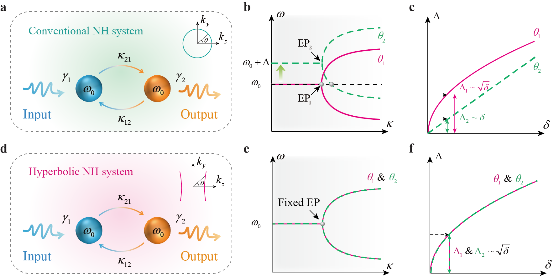
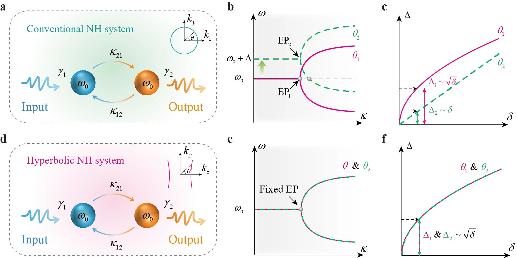
Figure 1. Dispersion engineering for angularly robust EP sensing. (a) Schematic of a conventional dielectric non-Hermitian coupled system with circular IFCs; (b) Angular variation of the Hamiltonian eigenvalue spectrum and the resulting shift away from the designed EP; (c) Change from a square-root to an approximately linear perturbation response following angular detuning; (d) HMM-integrated non-Hermitian coupled system with hyperbolic IFCs; (e) Suppressed angular dispersion of the Hamiltonian eigenvalue spectrum through phase compensation; (f) Preservation of the square-root EP response over a broad angular range. EP: exceptional point; IFCs: isofrequency contours; HMM: hyperbolic metamaterial.
To reduce this angular dependence, we introduce HMM layers into the coupled structure, as illustrated in Figure 1d. Their hyperbolic dispersion produces a change in the normal wavevector opposite to that of an ordinary dielectric. While the propagation phase accumulated in the dielectric layer decreases with increasing incident angle, the corresponding phase in the HMM increases. By choosing appropriate layer thicknesses, these opposite angular phase variations can compensate for each other, reducing the change in the total propagation phase without requiring the phase itself to vanish. This first-order phase compensation suppresses the angular dispersion of the coupled system[34,35]. The nearly overlapping eigenvalue trajectories in Figure 1e illustrate how the resonance frequencies can remain stable as the incident angle changes. Under these conditions, the EP-related square-root response can also be maintained over a wider angular range, as depicted in Figure 1f.
An angle-stable non-Hermitian coupled system requires a photonic bandgap whose frequency varies only slightly with the incident angle. In a conventional dielectric PC, the angular dependence of the bandgap arises from changes in the propagation phase accumulated within each unit cell. For a one-dimensional (1D) binary PC, the Bragg condition can be approximately expressed as[36-38]:
where ki,z and di (i = A,B) denote the normal wavevector and thickness of the corresponding layer, respectively. In conventional dielectric layers, ki,z decreases as the in-plane wavevector increases, making the accumulated phase dependent on the incident angle. The bandgap therefore shifts under oblique illumination. Reducing this shift requires the angular phase variations of the constituent layers to compensate for each other.
We consider a 1D binary PC composed of alternating HMM and Si layers, as shown in Figure 2a. The HMM is formed from a subwavelength indium tin oxide (ITO)/Si multilayer and described as an effective uniaxial medium using effective medium theory (EMT). For an ITO filling fraction (p), the effective permittivity tensor is given by:
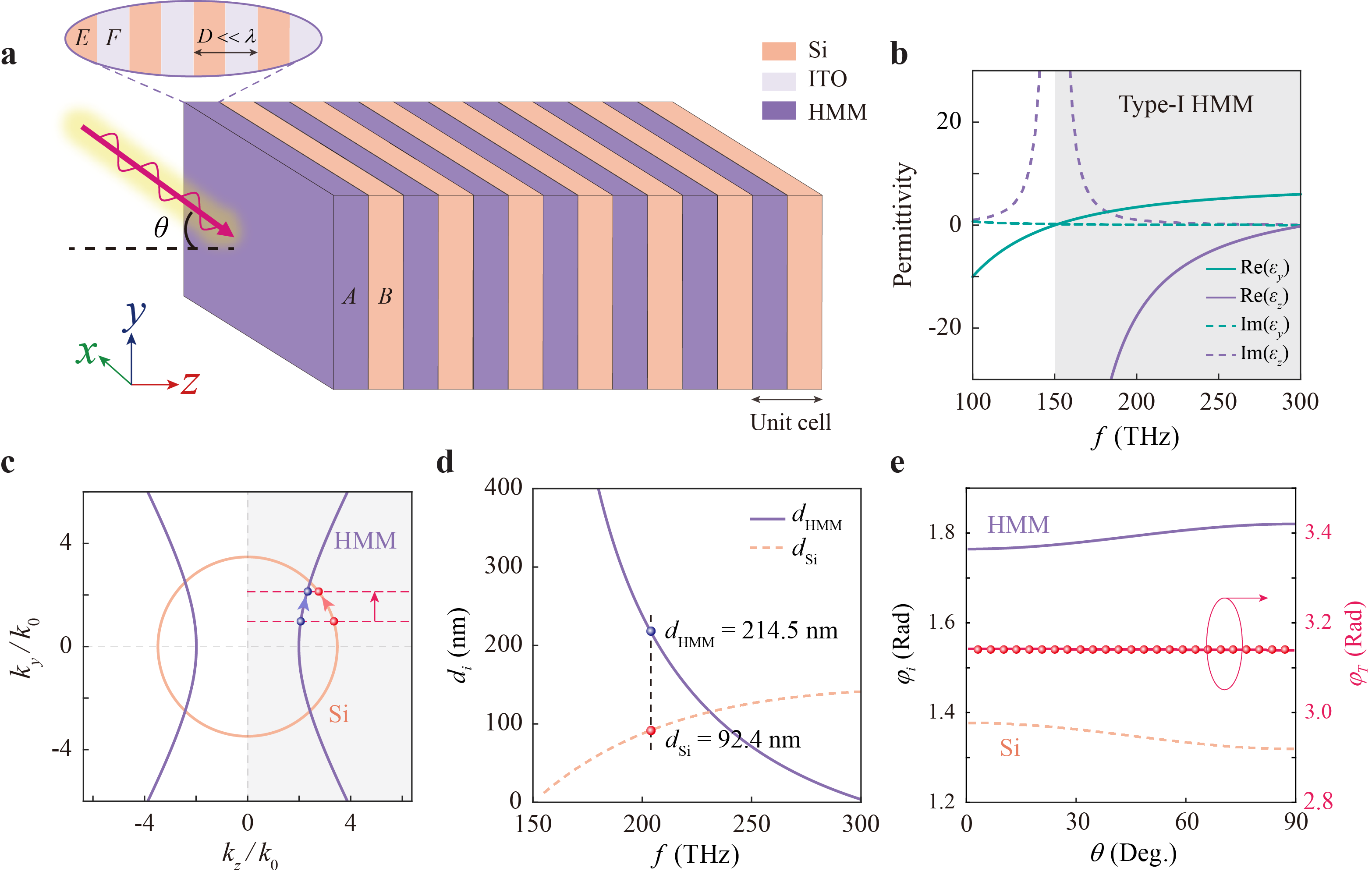
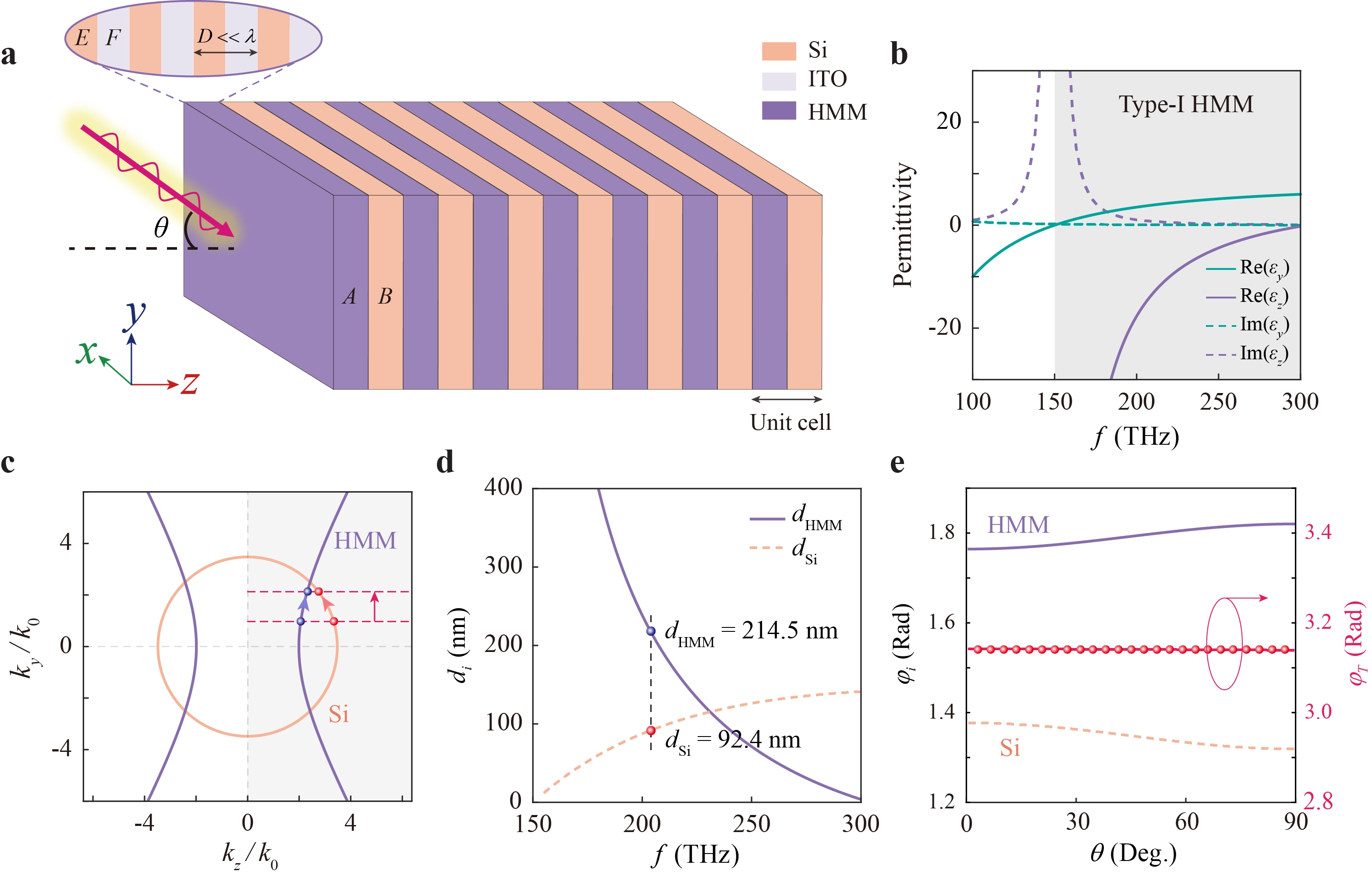
Figure 2. Hyperbolic dispersion engineering for angular phase compensation. (a) Schematic of the 1D binary PC composed of alternating HMM and Si layers, with the HMM formed from subwavelength ITO/Si multilayers; (b) Frequency dependence of the effective permittivity components calculated using EMT, with the shaded region indicating type-I hyperbolic dispersion; (c) IFCs of the HMM and Si layers for TM-polarized waves, showing their opposite angular dispersion; (d) Thickness combinations of the HMM and Si layers satisfying the first-order phase-compensation condition at different bandgap center frequencies; (e) Angular dependence of the propagation phases accumulated in the HMM and Si layers and their total phase per unit cell at f0 = 204.5 THz. IFCs: isofrequency contours; HMM: hyperbolic metamaterial; 1D: one-dimensional; PC: photonic crystal; ITO: indium tin oxide; EMT: effective medium theory; TM: transverse magnetic.
The in-plane and out-of-plane permittivity components are expressed respectively as[26,27]:
Here, p = 0.5, and the permittivity of Si is εSi = 12.11[39]. The permittivity of ITO follows the Drude model[40]:
where the high-frequency permittivity is ε∞ = 3.9, with plasma and damping energies of ℏωp = 2.48 eV and ℏξ = 0.016 eV, respectively. The damping term ξ accounts for the intrinsic loss of ITO.
The effective permittivity components in Figure 2b show that the HMM operates in the type-I hyperbolic regime, where Re(εx) = Re(εy) > 0 and Re(εz). This sign combination gives a two-sheet hyperboloid in momentum space. In contrast, type-II hyperbolic dispersion occurs when the in-plane components are negative and the out-of-plane component is positive, producing a one-sheet hyperboloid. For the type-I HMM considered here, the normal wavevector of transverse magnetic (TM)-polarized waves increases with the in-plane wavevector, opposite to its behavior in conventional dielectric layers. This difference allows the angular variations of the propagation phases in the HMM and Si layers to compensate for each other, reducing the angular dispersion of the photonic bandgap. The hyperbolic dispersion considered in this work originates from the anisotropic electric response of the metal-dielectric multilayer HMM and is therefore supported by TM polarization. A transverse electric (TE)-polarized hyperbolic response would require anisotropic magnetic permeability, which is not available in the present structure. However, magnetic or more complex anisotropic metamaterials may provide a possible route toward extending this mechanism to TE polarization.
For TM-polarized waves, the dispersion relation of the HMM is[26,27]:
where ky and kz denote the tangential and normal wavevector components, respectively. By comparison, the dispersion relation of isotropic Si is:
The two relations give opposite trends in the normal wavevector as the tangential component increases. For Si, kz decreases with increasing ky (∂kz,Si/∂ky < 0), whereas the type-I HMM exhibits an increasing normal wavevector in the operating regime (∂kz,HMM/∂ky > 0), as illustrated in Figure 2c. These opposite trends allow the angular phase changes in the two materials to compensate for each other. The first-order phase-compensation condition is obtained by setting the angular derivative of the total propagation phase to zero:
where dHMM and dSi are the thicknesses of the HMM layer and the Si layer, respectively. With ky = k0 sinθ, the condition can also be written as:
This condition requires the positive angular phase variation in the HMM to balance the negative variation in Si. It therefore suppresses the first-order change in the total propagation phase, rather than cancelling the accumulated phase itself. The resulting weak angular dependence allows the photonic bandgap to remain nearly unchanged over a broad range of incident angles.
The thickness combinations satisfying the phase-compensation condition at different bandgap center frequencies are plotted in Figure 2d. For the designed frequency of f0 = 204.5 THz, the HMM and Si thicknesses are dHMM = 214.5 nm and dSi = 92.4 nm, respectively. The angular dependence of the propagation phase in each layer is presented in Figure 2e. As the incident angle increases, the phase accumulated in Si decreases, while that in the HMM increases. Their opposite variations largely cancel, leaving the total phase per unit cell nearly unchanged. Although the localized resonances studied below operate near 210.7 THz rather than the bandgap center frequency, the phase compensation remains effective at this frequency, both with and without intrinsic loss, as verified in Sec. SA. This weak angular dependence of the propagation phase provides the basis for the angle-stable localized resonances and non-Hermitian coupled systems examined below.
3. Results and Discussion
To construct the non-Hermitian coupled system, we first consider two localized optical states supported by hyperbolic metacrystals. Their band structures are calculated using the transfer matrix method (TMM) and the Bloch theorem. For a periodic structure composed of alternating HMM and dielectric layers, the transfer matrix of one unit cell is given by[41]:
where the transfer matrix of each layer for TM-polarized waves takes the form:
For TM-polarized waves, we take the plane of incidence as the (y-z) plane and the stacking direction along (+z), with a time dependence of e-iωt. The tangential field vector is defined as ψ = (Ey, -Hx)T. For the i-th layer, the TM wave admittance is ηi = (ωε0ε//,i)/kz,i, where kz,i and di are the normal wavevector and thickness, respectively, and ε//,i is the in-plane relative permittivity. The transfer matrix in Equation (10) relates the fields at the two boundaries of the layer through ψ(zi) = Miψ(zi + di). With this definition and the adopted time dependence, the off-diagonal elements contain negative imaginary factors. The opposite transfer direction is described by
Applying the Bloch theorem, the dispersion relation of the infinite PC is obtained as[42]:
where K is the Bloch wavevector and d is the lattice period. The band structure is determined from this relation, with the photonic bandgap identified from the Bloch dispersion and the corresponding attenuation of the propagating modes. We construct two PCs with reversed stacking sequences. PC1 consists of alternating HMM and Si layers with the unit cell (AB), while PC2 has the reversed unit cell (B′A′). Both structures are designed to have a bandgap centered near 210 THz. Their band structures under normal incidence are shown in Figure 3a,b. Since the two PCs have the same constituent materials and layer thicknesses, their bulk band structures are nearly identical despite the reversed stacking order. The angular response is further examined using the reflectance spectra of finite PCs. For a structure consisting of (N) periods, the total transfer matrix is
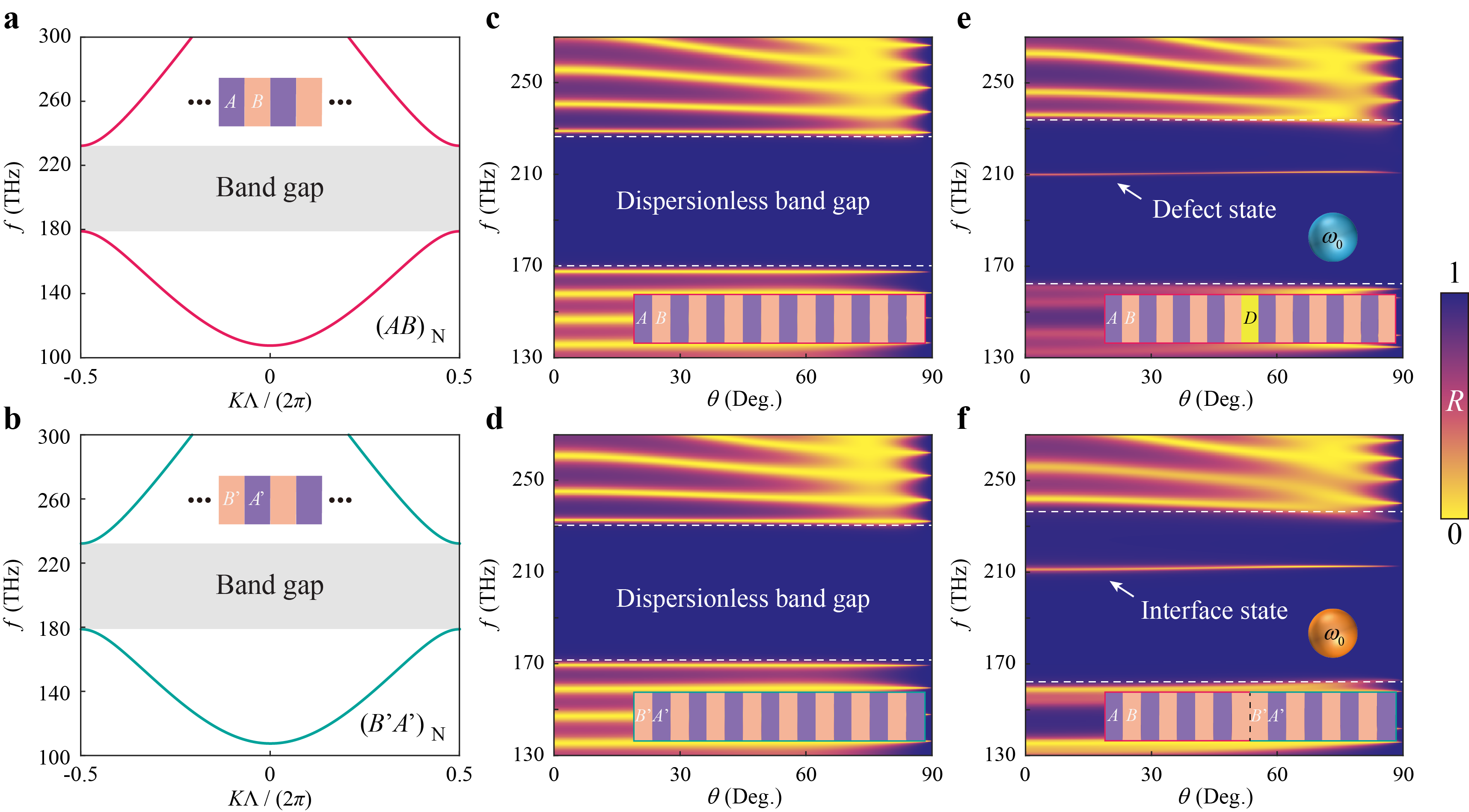
Figure 3. Angle-robust localized states in hyperbolic photonic metacrystals. (a,b) Calculated photonic band structures of PC1 (a) and PC2 (b) under normal incidence for TM-polarized waves; (c,d) Angle-dependent reflectance spectra of PC1 (c) and PC2 (d), showing nearly unchanged photonic bandgaps over the full angular range; (e,f) Angle-dependent reflectance spectra of the defect-cavity structure (AB)4D(AB)4 (e) and the heterojunction structure (AB)4(B′A′)4 (f), showing the weak angular dispersion of the defect and interface states, respectively. PC: photonic crystal; TM: transverse magnetic.
The reflection coefficient can then be obtained from
where Mw,h (w, h = 1 or 2) are the elements of the total transfer matrix. η0 and ηs denote the admittances of the incident and substrate media, respectively. The reflectance is then obtained as R = |r|2. The angle-dependent reflectance spectra of PC1 and PC2 are presented in Figure 3c,d, respectively. In both structures, the photonic bandgap remains nearly unchanged as the incident angle increases from 0° to 90°. The weak angular dispersion is consistent with the first-order phase compensation discussed in Section 2. Although the propagation phases in the individual HMM and Si layers vary with the incident angle, their opposite contributions keep the total phase nearly constant. The resulting bandgap can therefore support localized resonances with similarly weak angular dependence.
The reversed stacking sequences of PC1 and PC2 give rise to different reflection phases within their common bandgap. When the two PCs are joined, a localized interface state can form when the reflection phases satisfy[42,43]:
where
The two localized states are then combined in a PC heterostructure to form a second-order non-Hermitian coupled system. The structure, shown in Figure 4a, is written as (AB)3D(AB)q(B′A′)4, where the defect mode and the interface mode are separated by (q) periods of the intermediate PC. Although the two states are spatially separated, their evanescent fields overlap within the intermediate region, allowing energy to be exchanged between them. The coupling strength κ can therefore be adjusted by changing q. The system is described using temporal coupled-mode theory (CMT), as illustrated in Figure 4b. We denote the amplitudes of the defect and interface modes by a1 and a2, respectively. Their temporal evolution is governed by[44]
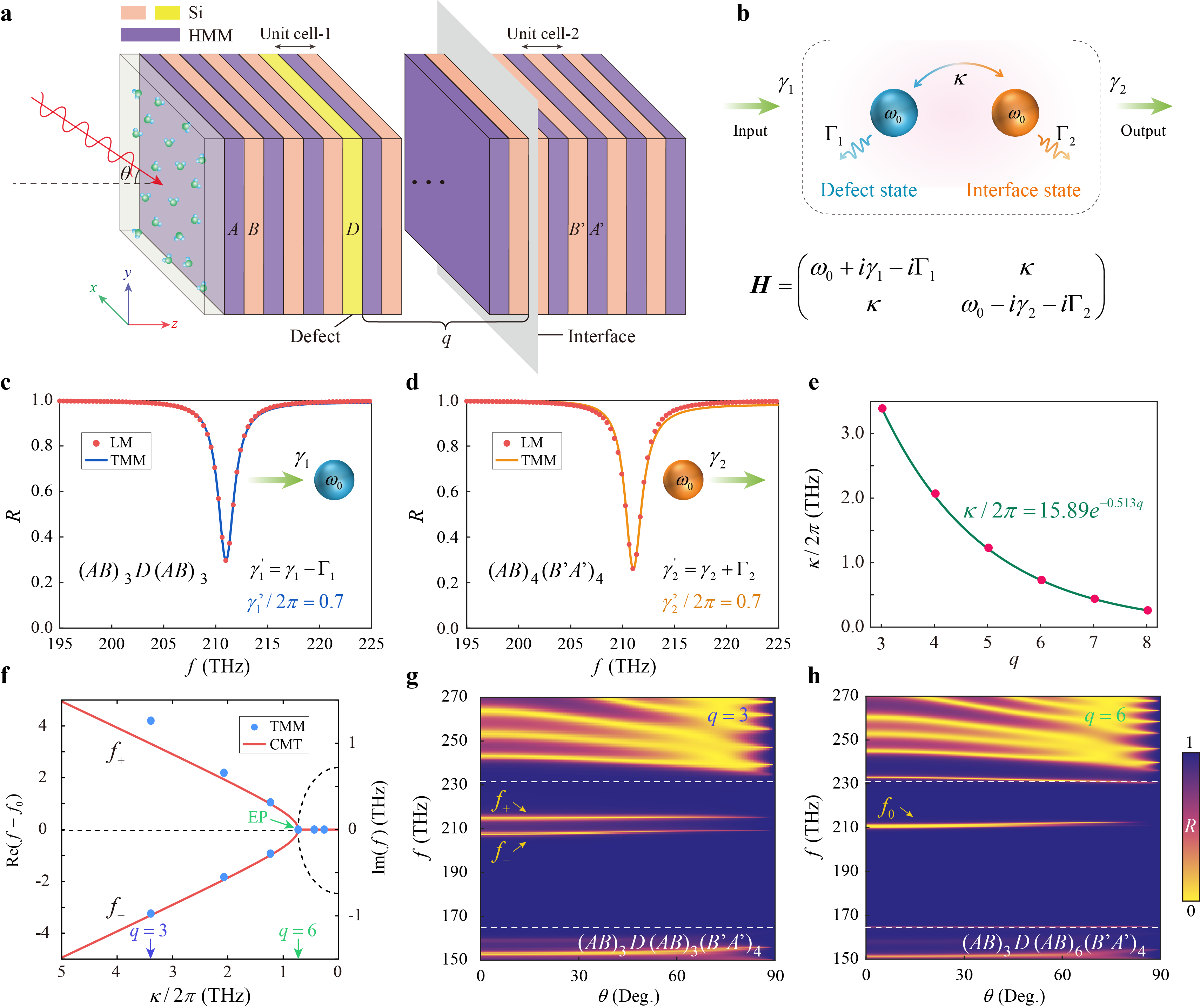
Figure 4. Coupling control and Hamiltonian EP in the non-Hermitian photonic heterostructure. (a) Schematic of the coupled structure (AB)3D(AB)q(B′A′)4, where the defect and interface modes interact through the intermediate PC region; (b) Effective two-mode coupled system with coupling strength κ, resonance angular frequencies ω1 and ω2, radiative loss rates γ1 and γ2, and intrinsic loss rates Γ1 and Γ2; (c) Reflectance spectrum of the isolated defect-state structure (AB)3D(AB)3 and the corresponding LM fit; (d) Reflectance spectrum of the isolated interface-state structure (AB)4(B′A′)4 and the corresponding LM fit; (e) Coupling strength (κ) as a function of the separation period number q, showing an exponential decay; (f) Comparison of the resonance frequencies obtained from TMM calculations with the eigenvalues of the effective Hamiltonian as the coupling strength varies; (g) Angle-dependent reflectance spectrum in the strong-coupling regime at q = 3, showing two separated resonance branches; (h) Angle-dependent reflectance spectrum at the Hamiltonian EP q = 6, where the two resonance branches merge and remain nearly unchanged with incident angle. EP: exceptional point; HMM: hyperbolic metamaterial; TMM: transfer matrix method; LM: Lorentzian model; CMT: coupled-mode theory.
where ωj, γj, and Γj (j = 1,2) denote the resonance angular frequencies, radiative loss, and dissipative loss of the harmonic defect and interface modes aj = Aje-iωt, respectively. The incident field at the left port is denoted by
For two modes with nearly identical resonance frequencies, ω1 = ω2 = ω0, and balanced effective gain and loss, γ1 - Γ1 = γ1 + Γ1, the corresponding dynamics in the system can be represented as HeV = ωV, where V = (a1,a2)T. Then, the effective Hamiltonian of the two-resonance system can be expressed as:
From Eq. (16), it can be found that the coupled system has PT-symmetry, (PT)He(PT)-1 = He[45], and the corresponding eigenvalues are:
For κ > γ0, the two eigenvalues have different real parts, corresponding to the unbroken PT-symmetric phase. As the coupling decreases to κ = γ0, the eigenvalues and eigenvectors coalesce at a second-order Hamiltonian EP. When κ < γ0, the eigenvalues split along the imaginary-frequency axis, and the system enters the PT-broken phase. To construct an ideal PT-symmetric reference system, we neglect intrinsic material loss and adjust the numbers of HMM periods in PC1 and PC2 to three and four, respectively, so that the effective gain and loss are balanced. The resonance parameters of the two localized states are obtained from the corresponding isolated structures, where the coupling between them is removed. The reflectance spectra of the isolated defect and interface states are shown in Figure 4c,d, together with the corresponding Lorentzian model (LM) fits. The resonance frequencies and linewidths are obtained from these spectra, while the radiative and intrinsic loss rates are determined using the coupled-mode relations and the reflection and transmission responses at resonance. The detailed extraction procedure is given in Sec. SC.
For the isolated defect-state structure (AB)3D(AB)3, the resonance frequency is ω1/2π = 211 THz, with an effective gain rate (γ1 - Γ1)/2π = 0.7 THz. The interface-state structure (AB)4(B′A′)4 has the same resonance frequency, ω2/2π = 211 THz, and an effective loss rate (γ2 + Γ2)/2π = 0.7 THz. The matching frequencies and effective gain–loss rates place the reference system close to the balanced PT-symmetric condition. The coupling strength is then varied through the separation period number (q). Since the two localized states interact through their evanescent fields, the coupling decreases approximately exponentially with their separation, following κ = κ0e-aq[46]. The coupling strengths extracted by fitting the TMM spectra with the CMT model are plotted in Figure 4e. The exponential dependence shows that the interaction between the two states can be controlled through the intermediate PC without changing the underlying localized-state structures.
The isolated-mode parameters are used as approximate uncoupled values as (q) varies. Changes in the intermediate periods primarily affect the intermode coupling, although deviations in the individual modal parameters may become more noticeable at small separations. The agreement between the TMM and CMT results provides a check of this approximation over the range considered (Sec. SC). Figure 4f compares the resonance frequencies obtained from the TMM spectra with the eigenvalues predicted by Equation (17). The calculated resonance frequencies follow the real parts of the effective Hamiltonian eigenvalues as the coupling strength decreases. In the strong-coupling regime, the two modes are separated in frequency. At q = 6, the coupling reaches the critical value κ = γ0, where the Hamiltonian eigenvalues and eigenvectors coalesce. Further increasing q reduces the coupling below the critical value and produces imaginary-frequency splitting.
The angular response of the coupled system is examined in Figure 4g,h. At q = 3, the two separated resonance branches remain visible over a broad range of incident angles, as shown in Figure 4g. When q = 6, the two branches merge at the Hamiltonian EP, as shown in Figure 4h. The resonance frequencies exhibit only weak angular variation, with the corresponding spectral features remaining nearly unchanged over the investigated range from 0° to 80°. This behavior follows from the phase compensation of the HMM and Si layers, which suppresses the angular dispersion of the two localized states. The resulting PT-symmetric reference system therefore provides an angle-stable Hamiltonian EP for examining the scattering response and its perturbation dependence in the following section.
The eigenvalue behavior near the Hamiltonian EP can be seen from the Riemann surface in Figure 5a. The two branches of the effective Hamiltonian eigenvalues meet at the EP, where the square-root dependence on the system parameters gives rise to a singular spectral response. We next examine how this degeneracy appears in the reflection spectra and how it affects the response to refractive-index perturbations. The calculated reflectance spectra for different separation periods q are presented in Figure 5b. Increasing q reduces the coupling between the defect and interface modes, causing the two resonance branches to approach each other. The results obtained from the TMM agree well with the CMT predictions over the incident angles considered. At the critical coupling condition of q = 6, the two resonances merge into a single reflection minimum near 210.7 THz. The angular dependence of this state is shown in Figure 5c. Owing to the phase compensation between the HMM and Si layers, the reflection minimum remains nearly unchanged in frequency as the incident angle increases, with particularly weak dispersion over the range from 0° to 60° (Sec. SA for the phase variation at 210.7 THz).
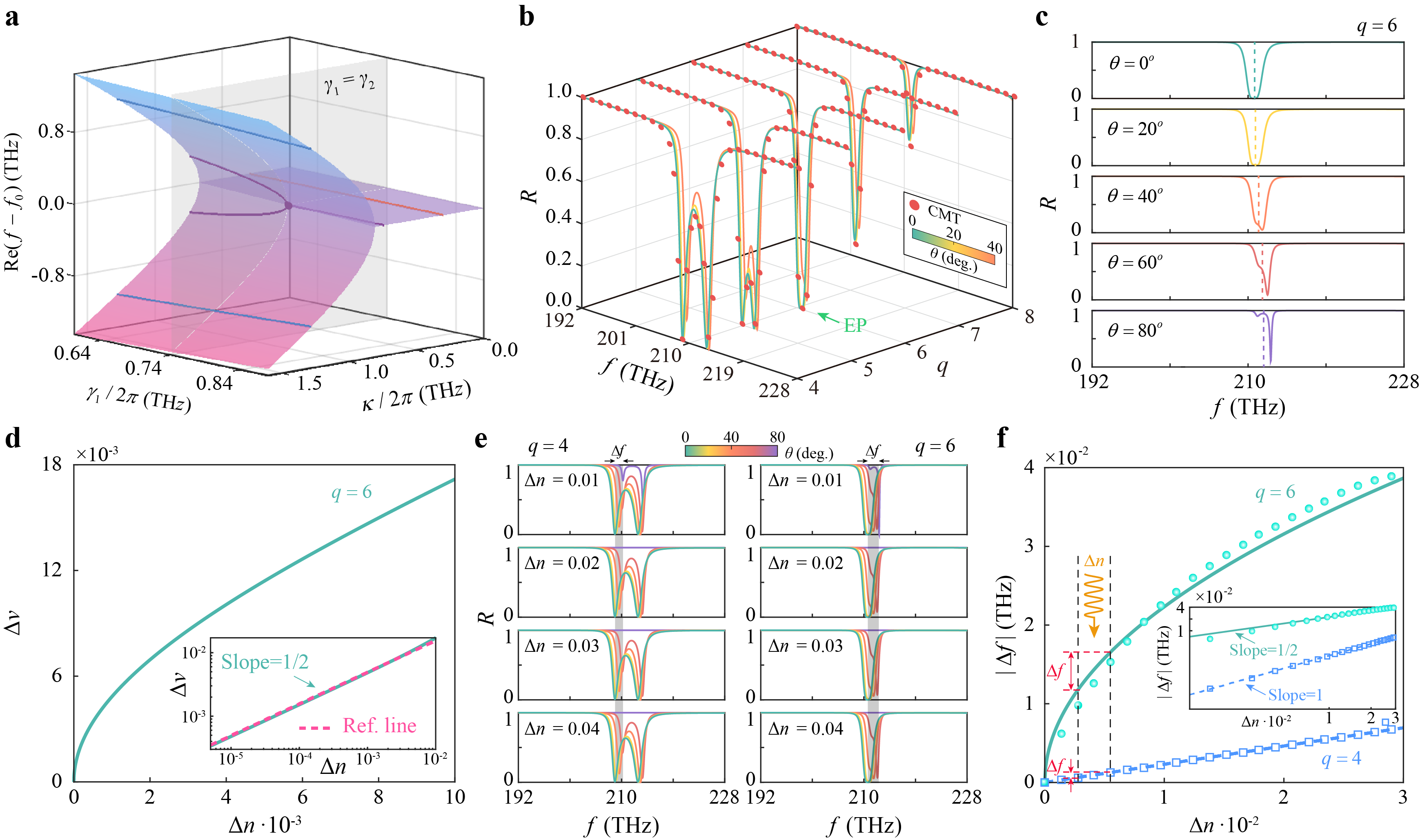
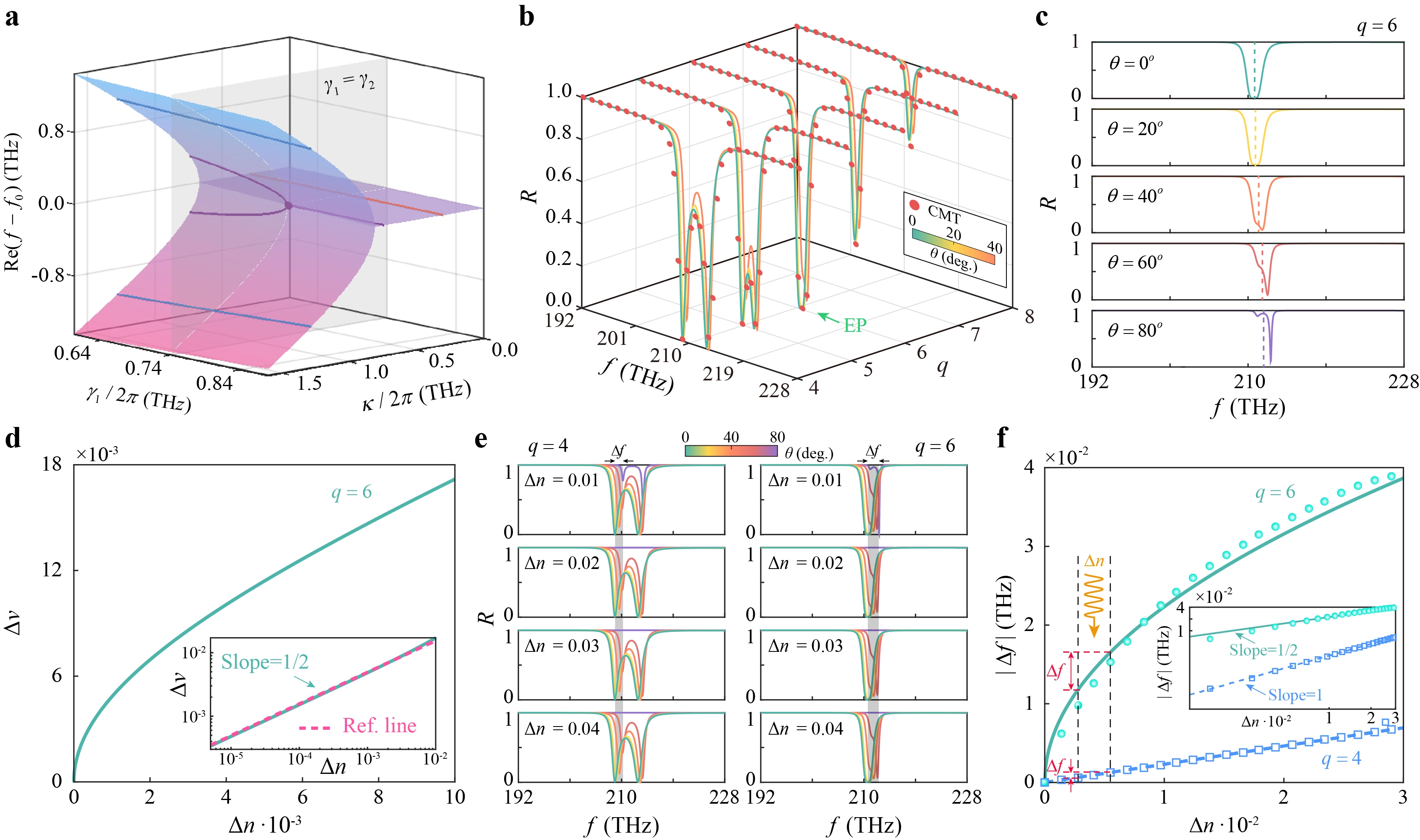
Figure 5. Scattering response and perturbation sensitivity of the PT-symmetric non-Hermitian coupled system. (a) Riemann surface of the real parts of the effective Hamiltonian eigenvalues, showing their coalescence at the EP; (b) Evolution of the reflectance spectra with the separation period number q, comparing TMM calculations with CMT predictions at different incident angles; (c) Angle-dependent reflectance spectra of the Hamiltonian-EP configuration at q = 6, showing the weak angular dispersion of the resonance near 210.7 THz; (d) S-matrix eigenvalue splitting ∆v as a function of the refractive-index perturbation ∆n, with a log-log fitting slope close to 0.5; (e) Angle-dependent reflectance spectra under different refractive-index perturbations for the non-EP reference configuration (q = 4) and the Hamiltonian-EP configuration (q = 6); (f) Resonance-frequency shift |∆f| versus ∆n for q = 4 and q = 6, showing approximately linear and square-root dependences, respectively. PT: parity-time; EP: exceptional point; TMM: transfer matrix method; CMT: coupled-mode theory; S-matrix: scattering-matrix.
The Hamiltonian eigenvalues describe the degeneracy of the effective coupled-mode system, whereas the measurable optical response is determined by its scattering properties. For the two-port structure, the incident and outgoing fields are related by[47,48]
For the reciprocal two-port system, we adopt the S-matrix convention[48], with the outgoing fields ordered as those at ports 2 and 1, respectively. The corresponding S-matrix is S = (t, r2; r1, t), where r1 and r2 are the reflection coefficients for incidence from the two sides, and (t) is the transmission coefficient. Its eigenvalues are
To examine the associated spectral changes, Figure 5e compares the angle-dependent reflectance spectra of the Hamiltonian-EP configuration (q = 6) with those of a non-EP reference configuration in the strong-coupling regime (q = 4). At q = 6, the reflection minimum shifts noticeably as the refractive index changes. The shifts also differ among incident angles, so the perturbed resonance spectra no longer overlap as closely as those of the unperturbed structure. By comparison, the q = 4 configuration exhibits smaller frequency shifts, and its resonance positions remain more closely aligned across the angular range considered. The difference is quantified in Figure 5f, where the resonance-frequency shift |∆f| is plotted against ∆n under normal incidence. At the Hamiltonian EP (q = 6), the frequency shift follows an approximately square-root dependence on the perturbation. Away from the EP (q = 4), the dependence is nearly linear, with a substantially smaller frequency shift over the investigated range. These results show that the same eigenvalue degeneracy responsible for the enhanced response at the Hamiltonian EP also makes its operating frequency more susceptible to refractive-index perturbations. The phase-compensation mechanism suppresses angular dispersion in the unperturbed structure, but it does not remove this perturbation-induced frequency shift. The comparison suggests that the scattering response and resonance-frequency stability need not be controlled through the same eigenvalue degeneracy. Previous studies have also considered sensing mechanisms that relax the direct dependence on an isolated Hamiltonian EP[49-53]. In the following section, we examine a PT-asymmetric configuration in which the effective gain and loss are no longer balanced. By moving away from the Hamiltonian EP while retaining an S-matrix EP, we seek to preserve the square-root scattering response with a smaller resonance-frequency shift.
This allows us to examine whether the scattering response can retain an EP without requiring the effective Hamiltonian to remain at its eigenvalue degeneracy. For the two localized modes, we define the effective gain and loss as g = γ1 - Γ1 and γ = γ2 + Γ2, respectively. When g ≠ γ, the effective Hamiltonian takes the form
where γ1 and Γ1 are the radiative and intrinsic loss rates of the defect mode, and γ2 and Γ2 are those of the interface mode. The effective Hamiltonian is obtained from the driven coupled-mode equations under the zero-reflection boundary condition at port 1. Under this condition, the incident field is related to the defect-mode amplitude, and the external driving term can be incorporated into the diagonal element of the Hamiltonian. The resulting effective gain, g = γ1 - Γ1, arises from the external excitation rather than an active material. The eigenvalues of this Hamiltonian describe the corresponding zero-reflection scattering solutions and should be distinguished from the resonance poles of the undriven structure. The derivation is given in Sec. SC. The eigenvalues of He2 are
Unlike the PT-symmetric system discussed in Figure 4, the two eigenvalues need not coalesce for one of them to reach the real-frequency axis. A real-frequency solution occurs when the coupling strength satisfies the BIC-associated condition[54-56]:
Under the condition κ2 = gγ, the effective Hamiltonian has one real eigenvalue, ω1 = ω0, while the other remains complex, ω2 = ω0 + i(g - γ). For g ≠ γ, the two eigenvalues have degenerate real parts and split imaginary parts, with one branch reaching the real-frequency axis. Similar eigenvalue behavior has been associated with unconventional BICs in non-Hermitian coupled systems[55]. For the present coupled-mode model, the same condition also gives zero forward reflection at the common resonance frequency, r1(ω0) = 0. The real-frequency eigenvalue and the reflection zero therefore occur at the same parameter setting. Together with the nonzero backward reflection, this produces the S-matrix EP discussed above. Here, the effective Hamiltonian is obtained under the zero-reflection boundary condition, and its real eigenvalue should be distinguished from the natural resonance poles of the undriven system. Further details are given in Sec. SB and Sec. SC.
We now examine this regime in the hyperbolic photonic heterostructure by including the intrinsic loss of the HMM. The isolated defect-state structure (AB)3D(AB)3 and interface-state structure (AB)4(B′A′)4 are considered separately to determine their resonance parameters. Figure 6a,b show their reflectance spectra together with the corresponding LM fits. The resonance frequencies and linewidths are extracted from these spectra, while the radiative and intrinsic loss rates are separated using the reflection and transmission responses at resonance, following the procedure in Sec. SC. The resulting parameters are used to construct the PT-asymmetric effective Hamiltonian. As in the balanced reference system, the coupling strength between the localized modes can be adjusted through the separation period number q. The values extracted from the TMM calculations follow an approximately exponential dependence on q, as shown in Figure 6c. Increasing the separation weakens the evanescent coupling while leaving the individual resonance frequencies nearly unchanged. This provides a means of reaching the condition in Equation (21). Figure 6d presents the evolution of the Hamiltonian eigenvalues with varying coupling strength. Compared with the balanced case with PT-symmetry, dissipation modifies the eigenvalue topology and shifts the critical point away from the original Hamiltonian EP condition. At q = 7, the coupling satisfies κ2 = gγ, and one eigenvalue of the zero-reflection effective Hamiltonian reaches the real-frequency axis while the other remains complex. This BIC-associated real-frequency condition is achieved through intrinsic-loss engineering without coalescence of the Hamiltonian eigenvalues. The corresponding reflectance spectra are shown in Figure 6e. The TMM results agree well with the CMT calculations as the separation period number changes. At q =7, a reflection minimum reaches zero near 210.7 THz, consistent with the real-frequency solution of the effective Hamiltonian. This zero-reflection condition is a property of the driven scattering response and does not, by itself, establish a non-radiating eigenmode. The independently calculated backward reflection remains finite, and the coalescence of the scattering eigenvectors is verified in Sec. SB. These results identify the operating point as a second-order S-matrix EP rather than a Hamiltonian EP. The angular dependence of the reflection spectrum at q = 7 is shown in Figure 6f. The zero-reflection feature remains close to 210.7 THz over a broad range of incident angles, with only a small frequency variation as the angle increases toward 80°. The weak angular dispersion follows from the phase compensation between the HMM and Si layers, which remains effective at the operating frequency (Sec. SA). The results thus establish a PT-asymmetric operating state in which the scattering EP is maintained without a corresponding Hamiltonian eigenvalue degeneracy. The following section examines its scattering eigenvalues and the response to refractive-index perturbations.
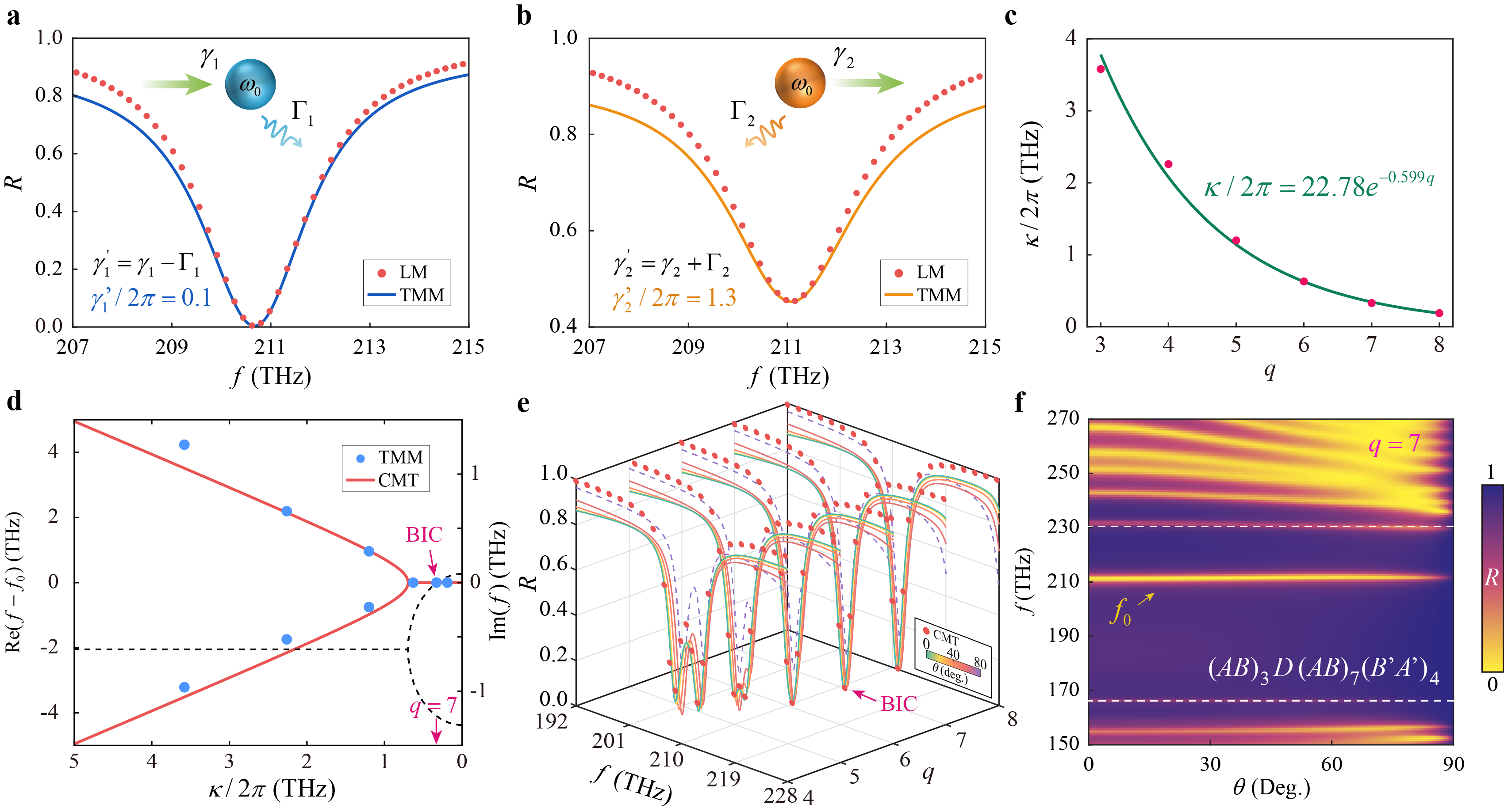
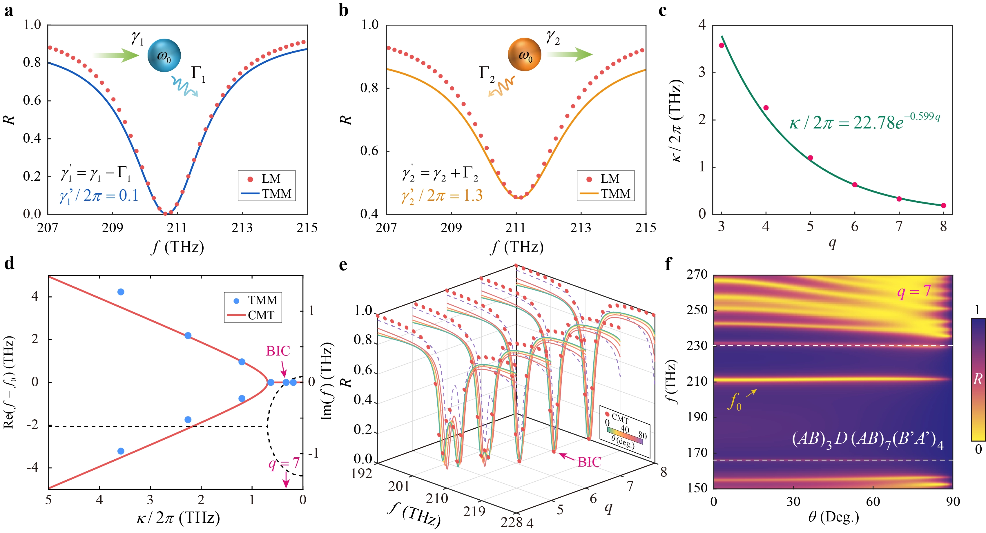
Figure 6. Loss engineering and the BIC-associated real-frequency state in the PT-asymmetric non-Hermitian system. (a) Reflectance spectrum of the isolated defect-state structure (AB)3D(AB)3 and the corresponding LM fit; (b) Reflectance spectrum of the isolated interface-state structure (AB)4(B′A′)4 and the corresponding LM fit; (c) Exponential dependence of the coupling strength κ on the separation period number q; (d) Evolution of the effective Hamiltonian eigenvalues with coupling strength, showing a BIC-associated real-frequency solution at q = 7 without Hamiltonian eigenvalue coalescence; (e) Reflectance spectra for different separation periods and incident angles, comparing TMM and CMT results; (f) Angle-dependent reflectance spectrum of the q = 7 structure under TM polarization, showing a nearly angle-independent zero-reflection feature near 210.7 THz. PT: parity-time; BIC: bound-state-in-the-continuum; TMM: transfer matrix method; CMT: coupled-mode theory; LM: Lorentzian model; TM: transverse magnetic.
We further examine the scattering properties and sensing response of the PT-asymmetric system at q = 7. The evolution of the two S-matrix eigenvalues with frequency is plotted in Figure 7a. The two branches meet near 210.7 THz, where the scattering eigenvalues become degenerate. The full two-port analysis in Sec. SB shows that the forward reflection coefficient vanishes at this frequency while the backward reflection remains finite. The S-matrix therefore has only one linearly independent eigenvector, confirming a second-order S-matrix EP. Unlike the PT-symmetric case discussed above, this scattering EP does not coincide with an EP of the effective Hamiltonian. To characterize the reflection response, we use the Smith chart to plot the complex reflection coefficient (r)[57], as shown in Figure 7b. The horizontal and vertical axes represent Re(r) and Im(r), respectively, while the circles indicate constant normalized resistance (Rn). The reflection coefficient is related to the normalized input impedance by Z = Rn + iXimp = (1 + r)/(1 - r), where Ximp is the normalized reactance. At the origin, (r = 0) and (Z = 1), indicating impedance matching and zero reflection. This representation allows us to follow the reflection response as the separation period number (q) varies.
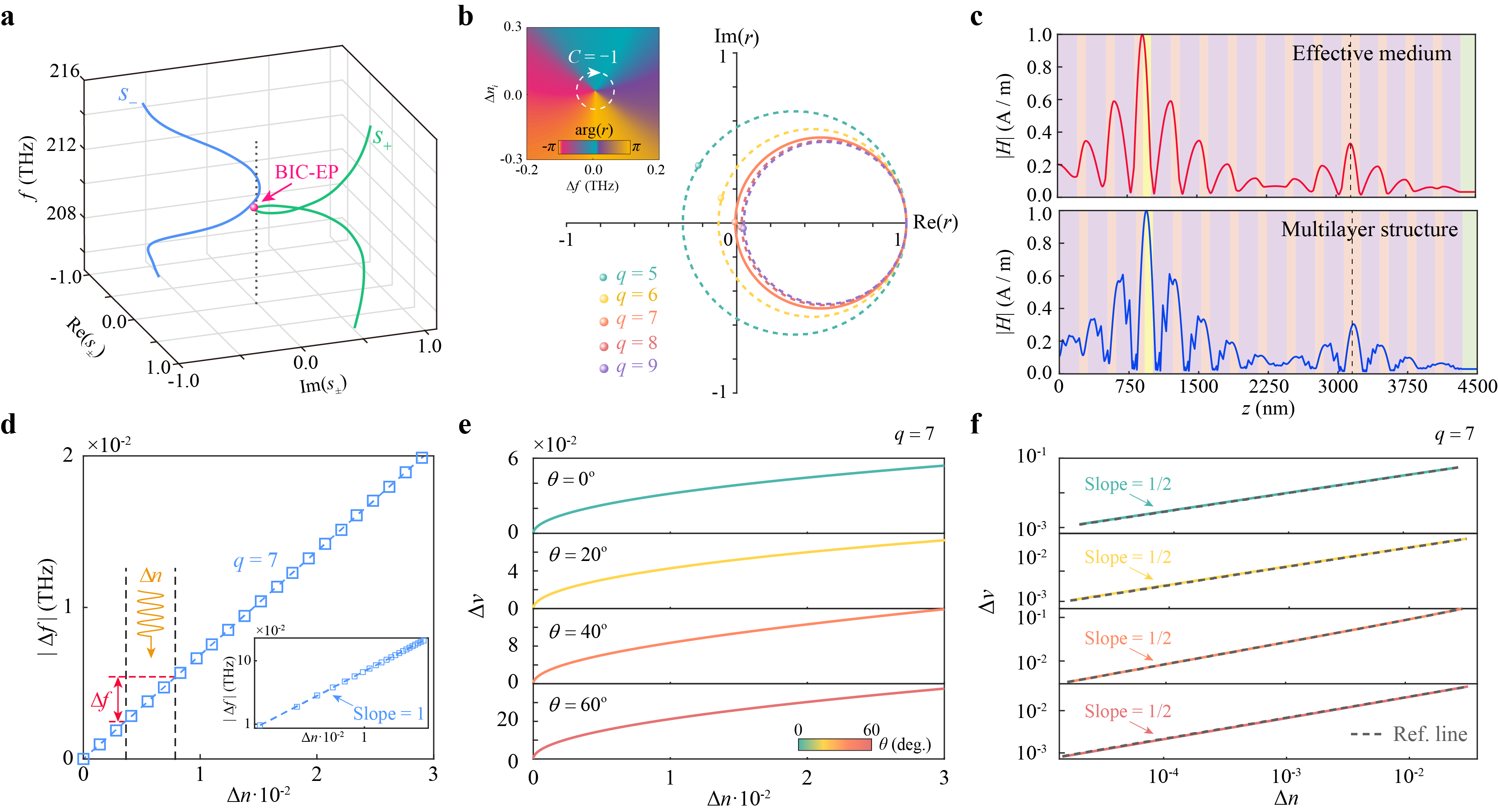
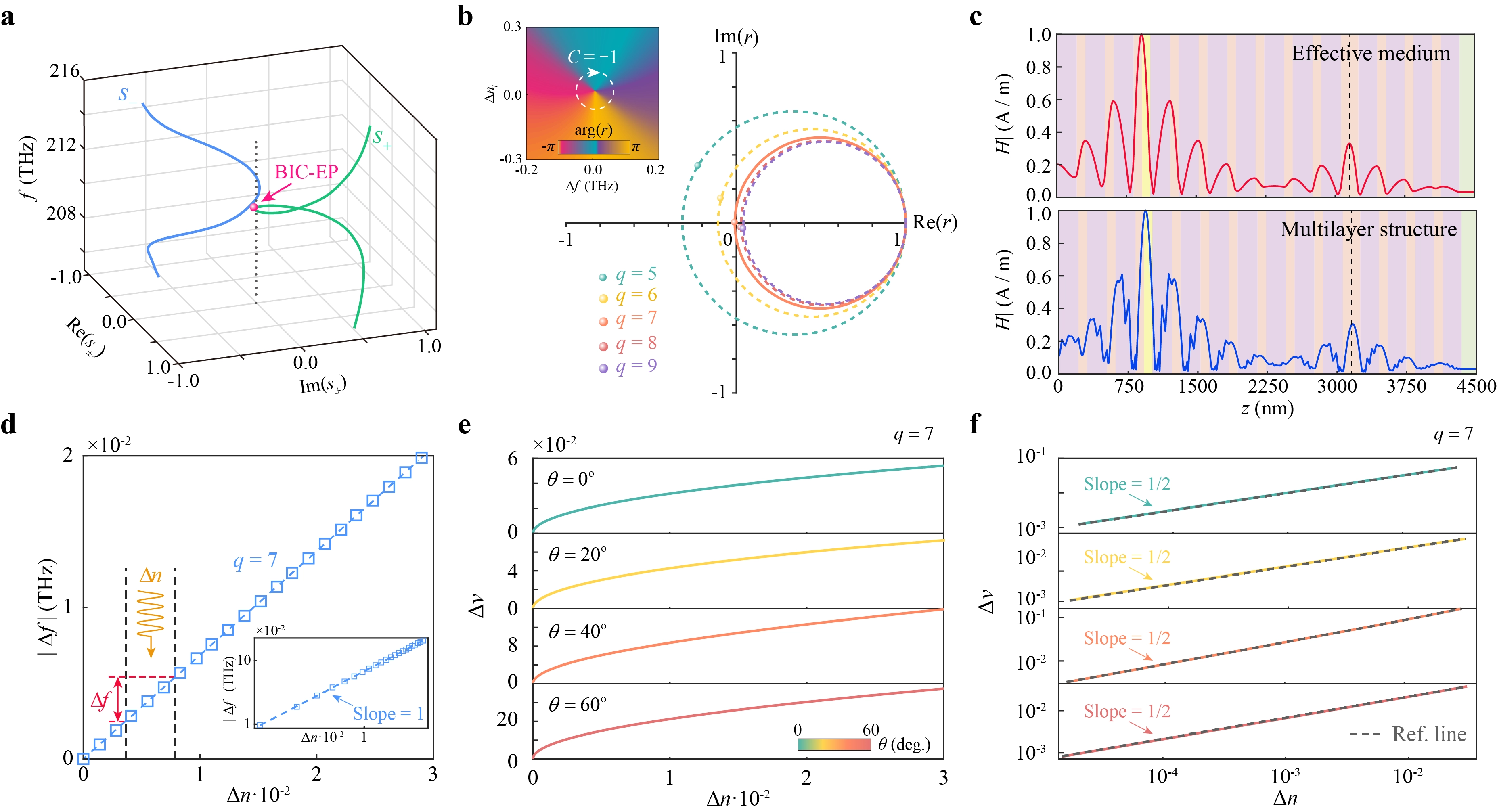
Figure 7. Scattering EP and sensing response of the loss-engineered non-Hermitian system. (a) Evolution of the S-matrix eigenvalues in the complex plane with frequency, showing their coalescence near 210.7 THz; (b) Evolution of the complex reflection coefficient in the Smith chart with increasing separation period number (q) under normal incidence, with the inset showing the reflection phase ϕ = arg(r) near the zero-reflection point; (c) Comparison of magnetic-field distributions between the actual multilayer structure and the EMT-equivalent structure at the BIC frequency under normal incidence, confirming the validity of the homogenized HMM model used for the PC design; (d) Resonance-frequency shift |∆f| versus refractive-index perturbation ∆n, showing an approximately linear dependence with a fitted log-log slope close to 1; (e) S-matrix eigenvalue splitting ∆v as a function of ∆n at incident angles of 0°, 20°, 40°, and 60°; (f) Corresponding log-log plots and fits, showing square-root scattering responses with slopes close to 0.5 over the investigated angular range. EP: exceptional point; S-matrix: scattering-matrix; EMT: effective medium theory; BIC: bound-state-in-the-continuum; HMM: hyperbolic metamaterial; PC: photonic crystal.
The constant-resistance circles in the Smith chart satisfy
At the operating frequency under normal incidence, the reflection coefficient moves toward the origin as q increases. It reaches r = 0 at q = 7 and moves away again for larger q. The corresponding normalized resistance approaches unity at the zero-reflection condition. The trajectory therefore provides a direct view of how the reflection zero is reached by changing the coupling between the two localized modes. The inset of Figure 7b shows the reflection phase ϕ = arg (r) as a function of frequency and the incident refractive index for q = 7. The reflection phase becomes undefined at (r = 0), producing a phase singularity[58]. Its topological charge is determined from the phase winding around a closed contour (L):
The calculation gives C = -1, corresponding to a phase vortex around the reflection zero. This phase singularity characterizes the zero of the scattering response. Together with the nonzero backward reflection and eigenvector coalescence established in Sec. SB, it provides further evidence for the S-matrix EP. It does not, on its own, establish a nonradiating natural eigenmode.
To verify the validity of the effective-medium approximation used in designing the hyperbolic metacrystal, Figure 7c compares the magnetic-field intensity distributions of the realistic multilayer HMM structure and the EMT-equivalent anisotropic HMM structure at the BIC frequency under normal incidence. The two field profiles agree closely, with pronounced field localization around the defect layer and the heterojunction interface. Their agreement indicates that the effective-medium description captures the main spatial features of the localized optical state in the investigated structure. We next consider the response to a refractive-index perturbation ∆n. In the PT-symmetric Hamiltonian-EP configuration, the perturbation produces a pronounced resonance-frequency shift, as discussed in Figure 5. In the present PT-asymmetric system, the operating point is no longer a Hamiltonian EP, although the S-matrix remains defective. Figure 7d shows the resulting resonance-frequency shift |∆f| as a function of ∆n under normal incidence. The frequency shift follows an approximately linear dependence, with a fitted slope close to unity in the logarithmic plot. Its magnitude is substantially smaller than that of the reference Hamiltonian-EP configuration. The corresponding reflection spectra are provided in Sec. SD. The scattering response behaves differently. Figure 7e shows the S-matrix eigenvalue splitting ∆v under incident angles of 0°, 20°, 40°, and 60°. As the refractive-index perturbation increases, the two scattering eigenvalues separate according to an approximately square-root dependence. The log-log plots in Figure 7f give fitted slopes close to 0.5 at all four angles. Thus, moving away from the Hamiltonian EP reduces the frequency drift without removing the characteristic scattering response of the EP.
The scattering eigenvalue splitting follows an approximately square-root dependence on the refractive-index perturbation over the angular range considered. This behavior gives a pronounced scattering response to small perturbations, while the resonance frequency remains comparatively stable. However, a larger eigenvalue response does not necessarily imply improved sensing precision, which also depends on noise in the optical measurement and the reconstruction of the scattering eigenvalues. The present results establish the angular stability and perturbation responsivity of the proposed structure, rather than an absolute noise-limited detection limit. The influence of structural variations on these properties is further examined in Sec. SE. Their combination allows the square-root scattering response to be retained without the large resonance-frequency shifts associated with the reference Hamiltonian EP. To examine the role of the HMM and loss engineering, we compared the proposed structure with Hamiltonian-EP, BIC-related, and scattering-EP sensing in an isotropic PC reference structure, as detailed in Sec. SF. The reference Hamiltonian EP exhibits a square-root frequency response at normal incidence, but this dependence becomes nearly linear at an incident angle of 5°. At the BIC-related operating point, the frequency response is linear and the resonance shifts noticeably with incident angle. S-matrix sensing recovers the square-root response at normal incidence, although the EP condition is lost as the angle increases. In contrast, the HMM-integrated structure retains a nearly square-root scattering response over a much wider angular range, together with reduced resonance-frequency drift.
4. Conclusion
In summary, we investigated a hyperbolic photonic metacrystal that combines dispersion and loss engineering for angle-robust non-Hermitian sensing. The opposite angular dispersions of the HMM and dielectric layers provide first-order phase compensation, keeping the localized defect and interface resonances nearly unchanged with incident angle. In the ideal PT-symmetric configuration, a Hamiltonian EP coincides with an S-matrix EP, where the square-root scattering response is accompanied by pronounced resonance-frequency shifts under refractive-index perturbations. By adjusting the effective gain-loss balance, we obtain a PT-asymmetric operating point satisfying κ2 = gγ. Under this condition, the zero-reflection effective Hamiltonian has a BIC-associated real-frequency solution without eigenvalue coalescence, while the S-matrix retains a second-order EP. The resulting structure preserves an approximately square-root scattering-eigenvalue response over incident angles from 0° to 60°, with substantially reduced resonance-frequency drift. Comparisons with an isotropic PC reference and calculations including structural deviations further clarify the respective roles of phase compensation and loss engineering. Recent studies have also reported complementary approaches to sensing, including loss-enhanced magneto-optical effects, body sensor networks based on flexible topological clothing, and cusp-singularity-enhanced chip-scale gyroscopes[59-61]. These results show that separating the scattering EP from the Hamiltonian EP provides a way to retain the nonlinear scattering response while improving spectral stability, offering an alternative approach to EP-based sensing beyond conventional eigenfrequency-based schemes.
Supplementary materials
The supplementary material for this article is available at: Supplementary materials.
Acknowledgements
During the preparation of this manuscript, the authors used ChatGPT (OpenAI) to assist with language editing and improving the clarity and readability of the text. No AI tools were used to generate or modify research data, numerical results, or scientific figures. All AI-assisted text was reviewed and revised by the authors, who take full responsibility for the final content of the manuscript.
Authors contribution
Li P: Data curation, investigation, validation, formal analysis, writing-original draft.
Du G, Yang Y, Chen H: Conceptualization, methodology.
Wang Y: Methodology, funding acquisition, writing-review & editing.
Guo Z: Conceptualization, supervision, funding acquisition, writing-review & editing.
Conflicts of interest
The authors declare no conflicts of interest.
Ethical approval
Not applicable.
Consent to participate
Not applicable.
Consent for publication
Not applicable.
Availability of data and materials
Data supporting the findings of this study are available from the corresponding author upon reasonable request.
Funding
This work was supported by the National Key R&D Program of China (Grant Nos. 2021YFA1400602, 2023YFA1406703, and 2023YFA1407600), the National Natural Science Foundation of China (Grant No. 12374294), Zhejiang Provincial Natural Science Foundation of China (Grant No. LR26A040001), the Fundamental Research Funds for the central Universities (Grant No. 2024FZZX02-01-02), the Chenguang Program of Shanghai Education Development Foundation and Shanghai Municipal Education Commission (Grant No. 21CGA22) and the Xiaomi Young Talents Program.
Copyright
© The Author(s) 2026.
References
-
1. Yu D, Humar M, Meserve K, Bailey RC, Chormaic SN, Vollmer F. Whispering-gallery-mode sensors for biological and physical sensing. Nat Rev Methods Primers. 2021;1:83.[DOI]
-
2. Aslam N, Zhou H, Urbach EK, Turner MJ, Walsworth RL, Lukin MD, et al. Quantum sensors for biomedical applications. Nat Rev Phys. 2023;5(3):157-169.[DOI]
-
3. Wang Z, Wan T, Ma S, Chai Y. Multidimensional vision sensors for information processing. Nat Nanotechnol. 2024;19(7):919-930.[DOI]
-
6. Li A, Wei H, Cotrufo M, Chen W, Mann S, Ni X, et al. Exceptional points and non-Hermitian photonics at the nanoscale. Nat Nanotechnol. 2023;18(7):706-720.[DOI]
-
7. Fernández-Alcázar LJ, Zhong Q, Kuhl U, Chen PY, El-Ganainy R, Kottos T. Parity-time symmetry and exceptional points in electronic circuits. Nat Electron. 2026;9(5):467-478.[DOI]
-
9. Hodaei H, Hassan AU, Wittek S, Garcia-Gracia H, El-Ganainy R, Christodoulides DN, et al. Enhanced sensitivity at higher-order exceptional points. Nature. 2017;548(7666):187-191.[DOI]
-
10. Qin H, Lv W, Zhang Z, Yang Z, Li J, Li M, et al. Photonic exceptional points in engineered materials and their emerging applications. Nat Rev Mater. 2026;11(6):453-468.[DOI]
-
11. El-Ganainy R, Makris KG, Khajavikhan M, Musslimani ZH, Rotter S, Christodoulides DN. Non-Hermitian physics and PT symmetry. Nat Phys. 2018;14(1):11-19.[DOI]
-
12. Kononchuk R, Cai J, Ellis F, Thevamaran R, Kottos T. Exceptional-point-based accelerometers with enhanced signal-to-noise ratio. Nature. 2022;607(7920):697-702.[DOI]
-
14. Landers S, Tuxbury W, Vitebskiy I, Kottos T. Noise-resilient exceptional point sensing with immunity to undesired perturbations. Sci Adv. 2026;12(9):eaeb7018.[DOI]
-
15. Mohammadi A, Mohammadi SA, Hosseini M. Effect of fabrication error on the sensitivity of a one-dimensional photonic crystal sensor for cancer detection. Sci Rep. 2026;16:7709.[DOI]
-
17. Zhen B, Hsu CW, Igarashi Y, Lu L, Kaminer I, Pick A, et al. Spawning rings of exceptional points out of Dirac cones. Nature. 2015;525(7569):354-358.[DOI]
-
19. Deng WM, Chen ZM, Li MY, Guo CH, Tian ZT, Sun KX, et al. Ideal nodal rings of one-dimensional photonic crystals in the visible region. Light Sci Appl. 2022;11(1):134.[DOI]
-
22. Zhou X, Zhang W, Cao W, Zhang X. Non-Hermitian floquet topological sensors for ultrasensitive detection of dynamic signals. Phys Rev Lett. 2025;135(10):106601.[DOI]
-
24. Lin Z, Li J, Song W, Su S, Sun J, Wu S, et al. Dissipative topological dynamics in optical waveguides: Sensitivity versus robustness. Phys Rev Lett. 2025;134(22):223802.[DOI]
-
26. Poddubny A, Iorsh I, Belov P, Kivshar Y. Hyperbolic metamaterials. Nat Photonics. 2013;7(12):948-957.[DOI]
-
28. Zhou Y, Guo Z, Tarazaga Martín-Luengo A, Lanza C, Álvarez-Pérez G, Yu C, et al. Fundamental optical phenomena of strongly anisotropic polaritons at the nanoscale. Nat Nanotechnol. 2026;21(1):23-38.[DOI]
-
29. Zhang H, Guo Z, Li Y, Yang Y, Chen Y, Chen H. A universal non-Hermitian platform for bound state in the continuum enhanced wireless power transfer. Front Phys. 2024;19(4):43209.[DOI]
-
30. Ge L, Feng L. Optical-reciprocity-induced symmetry in photonic heterostructures and its manifestation in scattering PT-symmetry breaking. Phys Rev A. 2016;94(4):043836.[DOI]
-
31. Park JH, Ndao A, Cai W, Hsu L, Kodigala A, Lepetit T, et al. Symmetry-breaking-induced plasmonic exceptional points and nanoscale sensing. Nat Phys. 2020;16(4):462-468.[DOI]
-
32. Li Z, Chen J, Li L, Zhang J, Yao J. Exceptional-point-enhanced sensing in an all-fiber bending sensor. Opto-Electron Adv. 2023;6(12):230019.[DOI]
-
33. Yan D, Shalin AS, Wang Y, Lai Y, Xu Y, Hang ZH, et al. Ultrasensitive higher-order exceptional points via non-Hermitian zero-index materials. Phys Rev Lett. 2025;134(24):243802.[DOI]
-
38. Wang Q, Xiao M, Liu H, Zhu S, Chan CT. Measurement of the Zak phase of photonic bands through the interface states of a metasurface/photonic crystal. Phys Rev B. 2016;93(4):041415.[DOI]
-
39. Palik ED. Handbook of optical constants of solids I. San Diego: Academic Press; 1985. Available from: https://api.pageplace.de/preview/DT0400.9780080523750_A23526768/preview-9780080523750_A23526768.pdf
-
41. Yeh P, Yariv A, Cho AY. Optical surface waves in periodic layered media. Appl Phys Lett. 1978;32(2):104-105.[DOI]
-
42. Xiao M, Zhang ZQ, Chan CT. Surface impedance and bulk band geometric phases in one-dimensional systems. Phys Rev X. 2014;4(2):021017.[DOI]
-
45. Bender CM, Boettcher S. Real spectra in non-Hermitian Hamiltonians having P T symmetry. Phys Rev Lett. 1998;80(24):5243-5246.[DOI]
-
50. Tang Y, Liang C, Wen X, Li W, Xu AN, Liu YC. PT-symmetric feedback induced linewidth narrowing. Phys Rev Lett. 2023;130(19):193602.[DOI]
-
52. Xu H, Wang L, Yuan L, Jin L. High-order perfect absorption in the absence of exceptional point. Phys Rev Lett. 2026;136(13):136902.[DOI]
-
54. Hsu CW, Zhen B, Stone AD, Joannopoulos JD, Soljačić M. Bound states in the continuum. Nat Rev Mater. 2016;1(9):16048.[DOI]
-
56. Kang M, Liu T, Chan CT, Xiao M. Applications of bound states in the continuum in photonics. Nat Rev Phys. 2023;5(11):659-678.[DOI]
-
57. Pozar DM. Microwave engineering. 4th ed. New York: John Wiley & Sons; 2012. Available from: https://ieeexplore.ieee.org/stamp/stamp.jsp?arnumber=7910095
-
58. Ergoktas MS, Kecebas A, Despotelis K, Soleymani S, Bakan G, Kocabas A, et al. Localized thermal emission from topological interfaces. Science. 2024;384(6700):1122-1126.[DOI]
-
59. Ruan YP, Tang JS, Li Z, Wu H, Zhou W, Xiao L, et al. Observation of loss-enhanced magneto-optical effect. Nat Photonics. 2025;19(1):109-115.[DOI]
-
60. Li Z, Liu Z, Wang Z, Deng Y, Yang S, Chen J, et al. Body sensor networks based on flexible topological clothing. Nat Electron. 2026;9(1):59-68.[DOI]
Copyright
© The Author(s) 2026. This is an Open Access article licensed under a Creative Commons Attribution 4.0 International License (https://creativecommons.org/licenses/by/4.0/), which permits unrestricted use, sharing, adaptation, distribution and reproduction in any medium or format, for any purpose, even commercially, as long as you give appropriate credit to the original author(s) and the source, provide a link to the Creative Commons license, and indicate if changes were made.
Publisher’s Note
Science Exploration remains a neutral stance on jurisdictional claims in published
maps
and institutional affiliations. The views expressed in this article are solely those
of
the author(s) and do not reflect the opinions of the Editors or the publisher.
Share And Cite


Science Exploration Style
Li P, Du G, Yang Y, Chen H, Wang Y, Guo Z. Loss-engineered scattering exceptional points in hyperbolic metacrystals for robust sensing. Light Manip Appl. 2026;1:202620. https://doi.org/10.70401/lma.2026.0020
Tips
Copy completed.
Submit a Manuscript
Author Instructions
Cite this Article
Article Metrics
0
View
0
Download
Cited
Article Updates

 Get citation
Science Exploration Style

Li P, Du G, Yang Y, Chen H, Wang Y, Guo Z. Loss-engineered scattering exceptional points in hyperbolic metacrystals for robust sensing. Light Manip Appl. 2026;1:202620. https://doi.org/10.70401/lma.2026.0020
copy
Share Link
copy