Airyprime beams: From concept to applications

Ziyuan Liu
1

,
Hongfei Gao
1
,
Yujia Zheng
1
,
Fei Wang
2
,
Guoquan Zhou
1,*
*Correspondence to:
Guoquan Zhou, College of Optical, Mechanical and Electrical Engineering (College of Intelligent Equipment Engineering), Zhejiang A&F University, Hangzhou 311300, Zhejiang, China.
E-mail: 19920006@zafu.edu.cn
Light Manip Appl. 2026;1:202624. 10.70401/lma.2026.0021
Received: September 17, 2026Accepted: November 03, 2026Published: November 04, 2026
Abstract
Structured light controls the spatial, spectral, polarization, and temporal degrees of freedom of optical fields to tailor propagation and light-matter interactions. Airy beams established a widely used route to self-acceleration, self-healing, and caustic focusing. Building on this foundation, two finite-energy Airyprime constructions reported in 2022 introduced derivative-field sources in Cartesian and circular geometries. The two branches share Airy-derivative building blocks but are mathematically non-equivalent. Their importance lies in showing how derivative placement, coordinate geometry, and finite-energy apodization reorganize the source field and thereby alter coherent energy redistribution, abrupt autofocusing, and the response to subsequent field engineering. This Review develops a claim-centered synthesis of Airyprime beams from source construction to potential application. It distinguishes intrinsic propagation physics from amplitude, phase, spectral, topological, coordinate, hybrid, and coherent-array control; separates measured optical fields from calculated responses and functional demonstrations; and evaluates performance through matched normalization, power, aperture, focal metrics, efficiency, recovery, and uncertainty. The available evidence supports functional laboratory demonstrations in selected particle-manipulation and vortex-parameter-detection tasks, while most communication, vectorial, spatiotemporal, nonlinear, fractional, and complex-medium concepts remain theoretical, numerical, or optical-field demonstrations. Practical Airyprime systems will require reproducible generation, common benchmarking conditions, compact implementation, and end-to-end validation under realistic operating conditions.
Keywords
Airyprime beams, structured light, abrupt autofocusing, optical field engineering, optical manipulation
1. Introduction
Structured light provides controlled access to spatial amplitude and phase, polarization, and spectrum; pulsed fields add temporal structure as a further physical degree of freedom. These controls can redirect trajectories, redistribute energy, form caustics and singularities, reshape focal volumes, and couple an optical field to a measured task. The roles of these controls must remain distinct. Changing a scalar envelope is different from adding polarization, and modifying a source field is different from changing the propagation operator. Airy-type fields are a useful example because their source definition, caustic evolution, and finite-energy experimental realization can be related directly.
Berry and Balazs identified a nonspreading, accelerating solution of the free-particle Schrödinger equation[1]. Exponential apodization supplied a finite-energy optical form, and cubic-phase modulation followed by Fourier transformation enabled optical Airy beams to be generated and observed[2,3]. Obstruction experiments established self-healing through redistribution of the unblocked spatial components[4], while circular Airy constructions redirected the caustic toward an axial autofocusing region[5]. Related Airy-wave studies include electron Airy beams[6], optical Airy-beam self-localization in nematic liquid crystals[7], and plasmonic Airy waves[8]. Plasma-channel and neutron-beam studies extend this cross-domain context[9,10]. General reviews and physical analyses provide context for these cross-domain extensions[11,12]. Airy-type wave packets have also been transferred to magnetostatic spin waves and generated in the X-ray regime[13-15]. Optical transmission and partially coherent circular Airy beams supply further methodological context[16,17]. These studies establish the broader Airy lineage but do not by themselves constitute evidence for an Airyprime source or application. Matter-wave Airy proposals provide another cross-domain theoretical precedent[18].
Derivative-based Airy fields require separate analysis because differentiation changes the complex source distribution rather than only its name. Replacing an Airy factor with its derivative shifts the zeros and extrema and changes the relative amplitudes and signs of the source lobes. Propagation therefore starts from a different complex field and redistributes energy differently. The result also depends on where the derivative is applied: an exponentially apodized Airy derivative is not the derivative of the complete apodized Airy field. Coordinate geometry adds another distinction because a separable Cartesian product and a derivative evaluated on a radial coordinate have different source measures, parameter definitions, and propagation symmetries. Later phase factors, transformations, hybrid envelopes, and coherent arrays modify these sources, but they are external operations rather than intrinsic source properties. Airyprime research therefore defines a derivative-field design space alongside conventional Airy beams; it does not imply universal performance superiority[19,20].
In this Review, the Airyprime framework refers to the finite-energy derivative-field constructions introduced in 2022[19,20]. The date sets the operational boundary of this Review rather than making an absolute claim about terminology. The Cartesian branch uses an Airy transformation of a prescribed coherent superposition of elegant Hermite-Gaussian modes to generate a separable finite-energy Airyprime field[20]. The circular branch defines an exponentially apodized radial Airy-derivative family in which derivative order zero gives the circular Airy beam and derivative order one gives the circular Airyprime beam[19]. These branches share derivative building blocks, but Cartesian separability is not radial symmetry and Airy-transform generation is not direct radial prescription.
Research developed within this framework is distributed across source construction, free-space propagation, abrupt autofocusing, phase and spectral control, coordinate transformations, vortices, coherent arrays, complex environments, vectorial and spatiotemporal extensions, optical-force models, particle manipulation, detection, communication-related metrics, and learning-assisted design[21-24]. This breadth creates a need for synthesis rather than an exhaustive catalogue. Organization by newly named beams can conceal that many variants arise from a limited set of composable amplitude, phase, topological, coordinate, envelope, or superposition operations. Likewise, isolated reports of peak enhancement, focal width, depth of focus, force, or bit-error rate cannot be compared without accounting for normalization, power, aperture, geometry, propagation model, and the measured quantity. Analytical possibility, numerical validation, optical-field measurement, functional laboratory demonstration, and practical-system operation also represent different evidentiary claims. Accordingly, this Review is organized around source construction, propagation physics, control operations, propagation environments, functionality, and application maturity, with the aim of identifying common mechanisms, experimental advances, and unresolved limitations rather than presenting the field as a paper-by-paper catalogue. Figure 1 links the Cartesian and circular source branches to propagation, field engineering, and selected laboratory functions. Its practical-system endpoint is prospective, not a demonstrated extension of every illustrated field.
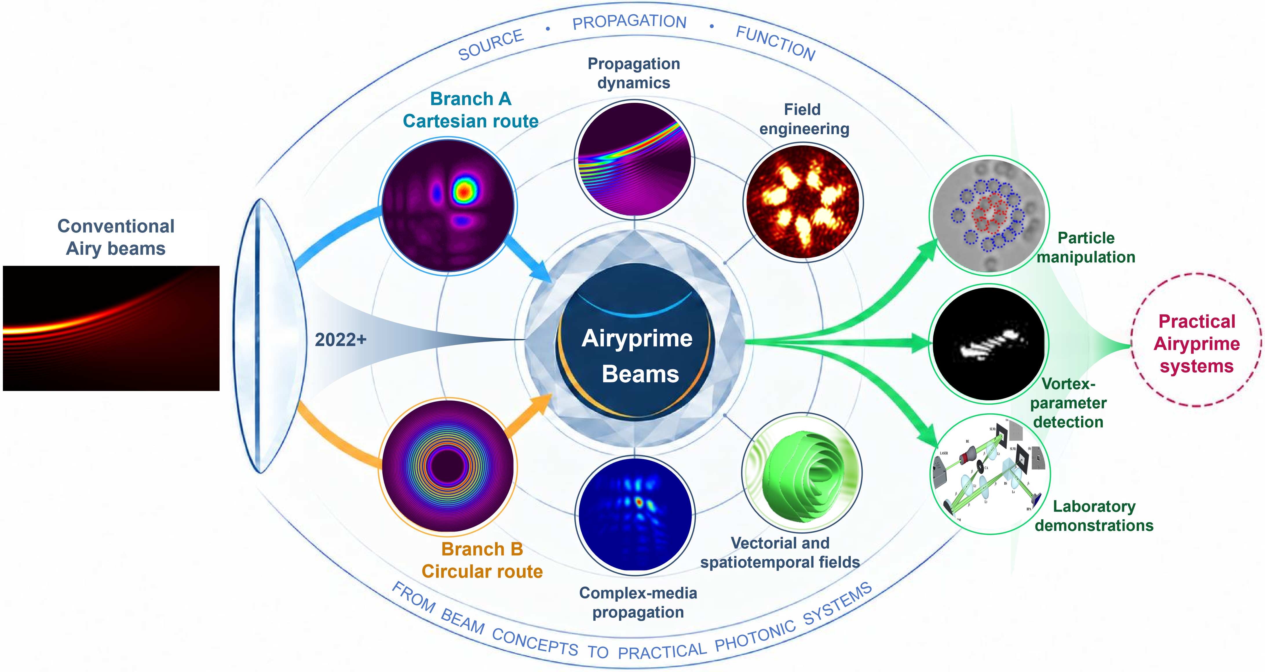
Figure 1. Overview of Airyprime beams from source construction to prospective applications. The Cartesian branch is generated through an Airy transformation, whereas the circular branch is defined by a radial Airy derivative. Reproduced from references[20,19]. CC BY 4.0. The surrounding examples connect propagation dynamics, field engineering, complex-media propagation, and vectorial or spatiotemporal extensions. Reproduced from references[25,26]. CC BY 4.0. Particle manipulation and vortex-parameter detection illustrate laboratory functions. Reproduced from reference[27]. CC BY 4.0. Reproduced with permission from reference[24]. Copyright © 2026 Chinese Laser Press. The propagation-dynamics, complex-media, and laboratory-demonstration illustrations were drawn by the authors. The dashed practical-system boundary denotes a future objective, not an established capability.
The Review follows this scientific progression. Section 2 establishes the adopted definitions, the two foundational source branches, and the conditional relationships among derivative and transformed fields. Section 3 examines branch-specific propagation physics, self-healing criteria, and the multi-objective assessment of focal performance. Section 4 organizes Airyprime-field engineering as a toolbox of amplitude, phase, spectral, topological, coordinate, hybrid, and coherent-superposition operations. Section 5 assesses propagation in turbulence-emulating systems, nonlinear models, fractional dynamics, and engineered external media, while Section 6 distinguishes polarization and temporal degrees of freedom from modal-basis and operator extensions. Section 7 evaluates optical forces, measured structures, particle manipulation, detection, and information-related functions according to the maturity of the demonstrated function. Section 8 identifies the benchmarking, integration, intelligent-design, and system-validation requirements separating current laboratory evidence from future practical platforms. Throughout, theoretical construction, numerical validation, optical-field experiment, functional demonstration, and practical-system evidence are treated as distinct levels so that mathematical richness is not conflated with experimental or application maturity.
1.1 Literature search and evidence classification
A structured literature search was updated on 12 October 2026. Records were identified through Crossref and PubMed metadata searches, publisher platforms, and backward and forward citation tracing. The core query combined “Airyprime”, “Airy prime”, “Airy derivative”, and “circular Airy derivative” with beam, pulse, wave packet, optical, autofocusing, self-healing, turbulence, nonlinear, fractional, vector, spatiotemporal, vortex, array, lattice, bottle, trapping, force, detection, communication, neural network, and inverse design. Title, abstract, keywords, cited references, and publisher metadata were screened, and DOI records were checked against the version of record.
Studies were included in the Airyprime evidence set when they explicitly defined, generated, propagated, measured, or used an Airy-derivative field within the adopted source framework, or when they supplied a directly relevant transformation or matched comparator. Conventional Airy-beam studies were retained only for historical background, methodological precedent, or an explicit within-study baseline and were not counted as Airyprime application evidence. Papers that mentioned Airyprime beams only in passing, duplicate records, records without sufficient bibliographic information, and studies outside the stated optical scope were excluded.
Peer-reviewed journal articles and publisher-posted accepted or online-ahead-of-print articles with a stable bibliographic record were eligible. When a preprint had a peer-reviewed version, only the version of record was used; a preprint without a peer-reviewed counterpart could inform horizon scanning only if it was clearly identified and could not raise an evidence grade above L2. Evidence was graded at the level of the specific claim rather than the paper as a whole. Thus, analytical predictions, numerical results, measured optical fields, observed functions, and end-to-end systems were recorded separately even when they appeared in one publication. The term audited evidence refers to the literature retained under these rules.
2. Conceptual Framework and Source Construction
2.1 Airy foundations and the adopted 2022 scope
The finite-energy Airy beam provides a natural reference for defining derivative-based Airy fields. In one transverse dimension, its source envelope can be written as
where Ai(s) is the Airy function of the first kind, s = x/w0 is the dimensionless transverse coordinate, w0 is the transverse scale, and a > 0 is the dimensionless apodization parameter. The exponential factor suppresses the oscillatory tail for negative arguments, whereas Ai(s) decays rapidly for positive arguments, yielding a finite-energy source[2]. Optical generation based on cubic-phase modulation and Fourier transformation subsequently established finite-energy Airy beams as experimentally accessible structured fields[3]. These results provide the physical background for Airyprime beams, but they do not define an Airy-derivative source.
In this Review, the Airyprime framework refers to the finite-energy Airy-derivative constructions developed from 2022 onward. Two source constructions anchor this framework: a Cartesian Airyprime field generated through an Airy transformation and a generalized circular Airy-derivative family defined directly in radial coordinates[19,20]. Throughout, the prime denotes differentiation with respect to the dimensionless Airy argument,
Importantly,
Thus, an apodized Airy derivative is not obtained simply by differentiating the complete finite-energy Airy field. This distinction, together with the coordinate geometry and generating operation, is essential for identifying what is meant by an Airyprime beam. The corresponding mathematical relationships are summarized in Figure 2 and Table 1.
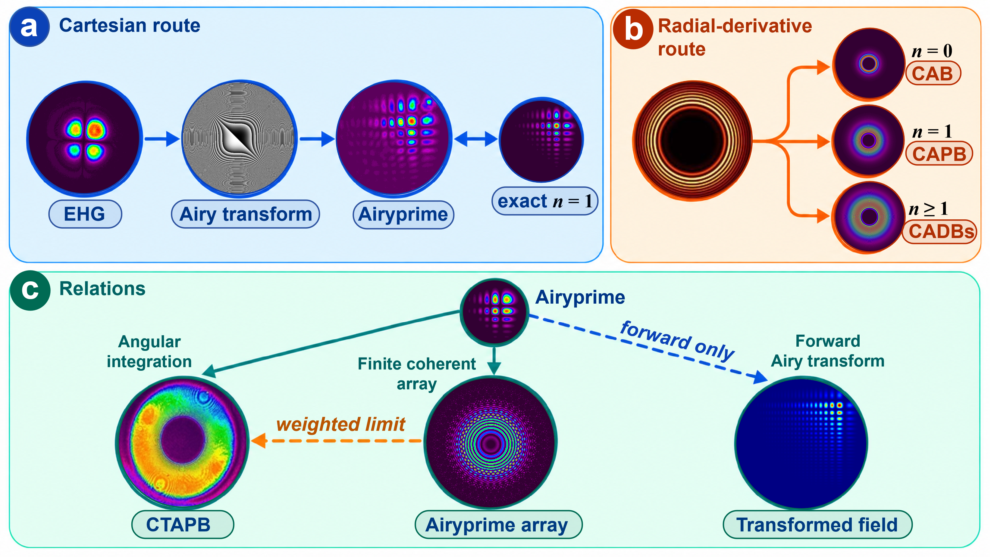
Figure 2. Mathematical genealogy of Airyprime fields. (a) Cartesian Airy transformation of a prescribed coherent elegant Hermite-Gaussian input and its relationship to the first-order Cartesian derivative family[20,28]; (b) Direct radial Airy-derivative prescription: n = 0 gives the CAB, n = 1 gives the CAPB, and higher orders extend the CADB family[19]. Reproduced from reference[19]. CC BY 4.0; (c) Continuous angular integration, finite coherent sampling, and forward Airy transformation[29-31]. The illustrations associated with reference[30,31] were independently generated by the authors using the equations or methods reported in those studies; they are not reproduced images from the cited publications. The weighted sampling limit requires matched geometry, weights, and phases. The solid two-way arrow in (a) identifies the matched n = 1 field form, not a reversible optical transformation; the dashed arrow in (c) denotes a forward transformation only. CAB: circular Airy beam; CAPB: circular Airyprime beam; CTAPB: circularly transformed Airyprime beam; CADB: circular Airy derivative beams.
Table 1. Definitions and mathematical relationships of representative Airyprime-related fields. The source definitions and derivative orders follow the foundational and early Airyprime studies[2,19-21]. Coordinate geometry and later conditional constructions are documented separately[29,30,32]. The conventional finite-energy Airy beam is included as background only; the inward radial argument is retained as (r0-r)/w0, and conditional transformations are not presented as source equivalences or reversible mappings.
| Field | Representative source definition | Coordinate geometry | Derivative order |
| Finite-energy Airy beam[2] | 1D Cartesian; separable 2D | n = 0 | |
| Finite-energy Cartesian Airyprime beam[20] | Separable Cartesian; shifted x and y | First derivative in each coordinate | |
| Generalized circular Airy derivative beam[19] | Axisymmetric radial coordinate | Integer n ≥ 0 | |
| CAPB (first-order CADB)[19] | Same inward radial coordinate | n = 1; apodization is not differentiated | |
| Circularly transformed Airyprime beam[29] | Angular integral of Cartesian fields | Two Cartesian derivatives inside the integral | |
| Discrete Airyprime beams array[30] | Discrete rotated | First derivatives in each beamlet | |
| Generalized Airy derivative beam[32] | Cartesian derivative family | Specified derivative order |
CAPB: circular Airyprime beam; CADB: circular Airy derivative beams.
2.2 Two source constructions: Cartesian Airy transformation and circular derivatives
At the source level, replacing an Airy factor by its derivative changes the amplitude zeros and sign structure, but does not by itself specify an optical beam. Generation procedure, coordinate geometry, apodization, and subsequent propagation model must also be defined. The adopted 2022 framework therefore contains two related but distinct constructions. One produces a separable Cartesian Airyprime field through an integral transformation; the other introduces Airy derivatives directly into an axisymmetric radial source. Their shared use of Ai′(·) does not make the resulting fields mathematically identical.
For the Cartesian branch, the starting field is a prescribed coherent superposition of 00, 01, 10, and 11 elegant Hermite-Gaussian modes rather than an arbitrary Gaussian beam. With positive transformation scales α and β, Gaussian input width w0, τ = w02/4α2, and γ = w02/4β2, the input and the corresponding two-dimensional Airy transformation can be expressed as[20]
The transformed field takes the separable form
The exponential factors provide the finite-energy apodization, while the coordinate shifts and decay parameters follow directly from the selected input and transformation scales. In particular, at fixed w0, changing α or β simultaneously changes the corresponding apodization parameter; these quantities are therefore not independent corrections appended to an otherwise fixed Airyprime field. Experimentally, the prescribed modal superposition was synthesized with a spatial light modulator, and the Airy transformation was implemented through a cubic-phase 4f system, allowing the generated field and its propagation to be measured directly[20]. The construction should therefore be understood as a matched input-transformation pair rather than as a generic conversion of Gaussian illumination into an Airyprime beam.
The circular branch starts from a different source geometry. A generalized circular Airy derivative beam is defined, apart from an overall amplitude factor, as
where r0 is the reference ring radius, w0 > 0 is the radial scale, a > 0 is the apodization parameter, and n is a nonnegative integer[19]. Within this family, n = 0 gives the circular Airy beam (CAB), whereas n = 1 gives the circular Airyprime beam (CAPB). Higher values of n generate higher-order circular Airy derivative beams. The inward argument sr is part of the definition and fixes the orientation of the radial oscillatory structure. As in the Cartesian construction, exponential apodization renders the ideal derivative profile finite in energy; a hard aperture is not part of Equations (7) and (8), although any experimental implementation is necessarily finite. CAB and CAPB fields have both been generated experimentally using holographic encoding and spatial filtering[19].
The two branches therefore share finite-energy Airy-derivative building blocks but differ at the source level. Equations (4)-(6) describe a product of two Cartesian derivative factors, whereas Equations (7) and (8) define a single derivative evaluated on a radial coordinate. Their scale parameters have different physical meanings, and their power integrals involve different coordinate measures. Correspondingly, Cartesian separability and cylindrical symmetry lead to different analytical descriptions of propagation[19,20]. Re-expressing the Cartesian field in polar coordinates does not convert it into the radial CAPB, nor does the experimental realization of both fields imply source equivalence[29]. This distinction is central to the terminology adopted throughout the Review: the two constructions are related through their Airy-derivative structure, but they should not be treated as interchangeable representations of a single universal field.
2.3 Derivative-family relationships and conditional transformations
Derivative order provides one route for extending the framework without introducing a separate physical category for every integer n. In the generalized Cartesian Airy-derivative family, both transverse factors carry the same derivative order together with exponential apodization and a specified source-peak normalization[28]. Under the appropriate symmetric coordinate, scale, apodization, and amplitude identifications, its n = 1 member reproduces the Cartesian Airyprime source represented by Equations (4)-(6). Higher derivatives can in turn be expressed through combinations of Ai(·) and Ai′(·) with coordinate-dependent polynomial coefficients. These relations are mathematical consequences of the Airy differential equation and should not be interpreted as constant-weight superpositions of complete Airy and Airyprime beams. Experimental generation of a selected n = 2 field further demonstrates the physical accessibility of this derivative hierarchy[28], although the propagation consequences of increasing n are considered separately in Section 3.
A different extension is obtained through coordinate transformation. The circularly transformed Airyprime beam is constructed by coherently integrating shifted and rotated Cartesian Airyprime fields over the azimuthal angle[29]. Because two Cartesian derivative factors remain inside this angular superposition, its source definition differs fundamentally from the single radial derivative factor of the CAPB. The target field has nevertheless been synthesized holographically and measured experimentally[29]. In Figure 2 and Table 1, it is therefore represented as a transformation-derived circular field rather than as an alternative notation for the CAPB.
Discrete Airyprime-beam arrays provide a related connection through coherent superposition. A finite array is formed from rotated and displaced Cartesian Airyprime beamlets[30]. With matched offsets, angular conventions, and quadrature weights, progressively denser angular sampling can approach the corresponding continuous angular construction[29]. This limiting relationship does not make a finite array identical to the circularly transformed field, nor does fixing the amplitude of individual beamlets imply equal total input power. The distinction becomes particularly important when array geometries are compared in terms of focusing or energy concentration, which is discussed in Section 4.
Airy transformation of an Airyprime input introduces yet another mathematical connection. For an input factor of the form
A particularly useful special case occurs when the transformation scale satisfies b = -w0 in one coordinate. Under this condition, cancellation of the cubic spectral phase produces a displaced combination of the zeroth- and first-order Hermite-Gaussian modes; obtaining the corresponding form in both transverse coordinates requires the analogous condition c = -w0[31]. This result establishes a specific forward transformation under matched parameters, but not a general inverse transformation or a closed Airy-Airyprime conversion cycle. Taken together, these derivative and transformation relationships define the mathematical boundaries of the Airyprime framework used here. With the source fields specified, the next question is how the Cartesian and circular constructions redistribute energy during propagation and why they develop distinct intensity-enhancement and abrupt-autofocusing behavior.
3. Propagation Physics and Multi-Objective Autofocusing
3.1 Cartesian propagation and coherent intensity redistribution
Once the source fields have been specified, their differences become more apparent during propagation. For the separable Cartesian Airyprime field, the exact paraxial solution can be decomposed in each transverse coordinate into an Airyprime-related term and an Airy-correlated term. The variables s, w0, and a retain the definitions used in Section 2.2; k = 2π/λ is the wavenumber, z0 = k w02 is the Rayleigh-type longitudinal scale, and ζ = z/z0 is the normalized propagation distance. With u = s- ζ2/4 + i a ζ and the propagation factor P defined below, the one-dimensional field may be written as
In Equation (10), C is the overall source-normalization constant inherited from the Cartesian field definition, and P is the common propagation factor appearing in Equation (10). The corresponding symmetric two-dimensional field is the Cartesian product Ex Ey[33]. The notation therefore matches Section 2.2: x and y label the two separable coordinates, while Ax and Bx denote components of one analytical propagation solution rather than independently launched beams. The Airy-correlated contribution vanishes at the source plane and emerges during propagation.
This decomposition clarifies an important point about the observed peak-intensity enhancement. For the unchirped cases analyzed in[33], the interference term 2Re[AxBx*] is nonpositive. The increased maximum intensity therefore cannot be interpreted as constructive interference between separately propagating Airyprime and Airy beams. Instead, diffraction continuously redistributes the spatial weights of the Airyprime-related term, the Airy-correlated term, and their signed cross contribution. In an ideal lossless paraxial system, the integrated optical power is conserved when the computational or physical aperture captures the full field. A larger local maximum must therefore be accompanied by redistribution elsewhere in the transverse profile rather than by optical gain. Figure 3c contrasts a Cartesian intensity profile with circular annular focusing geometry; it is a mechanism illustration, not a measurement of separate interference terms.
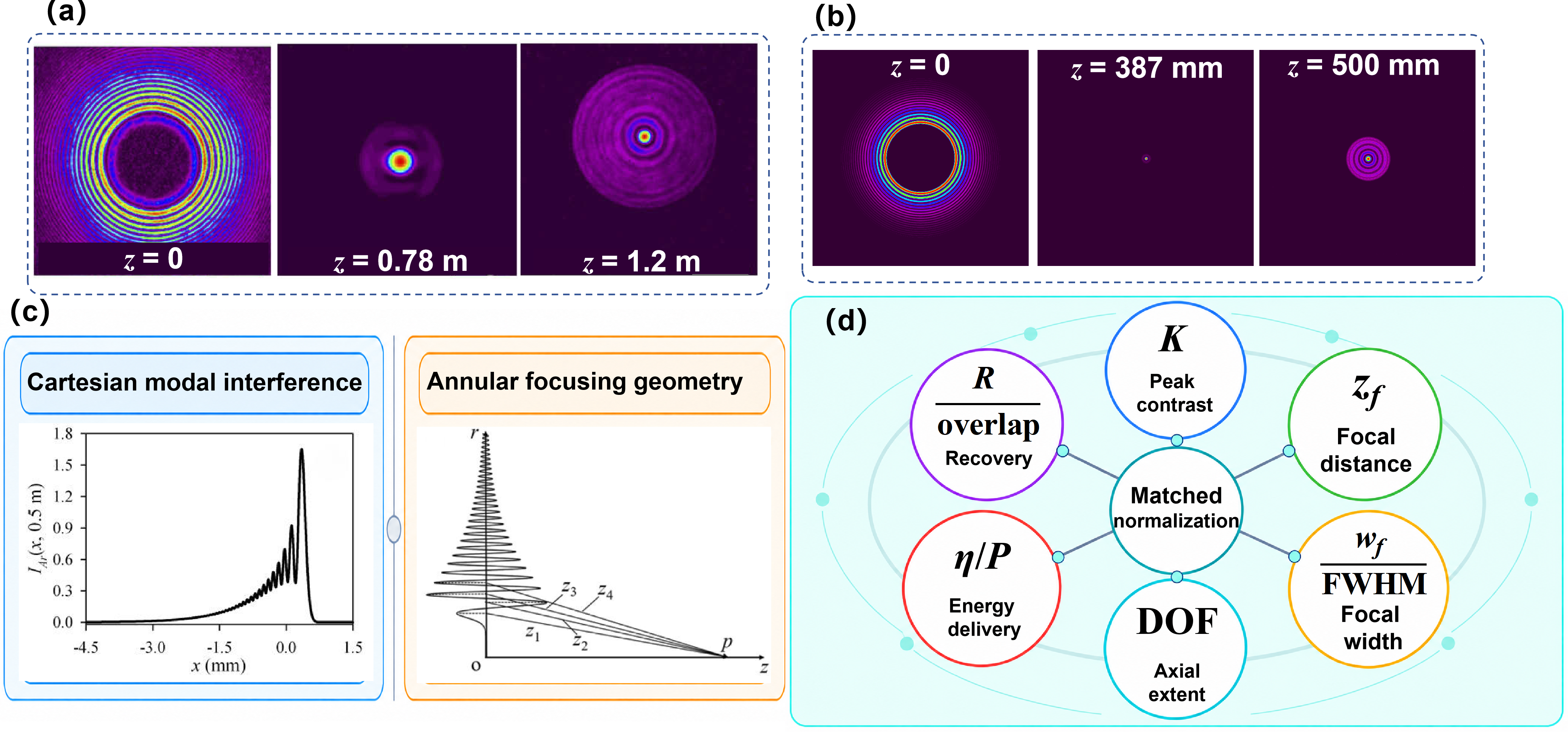
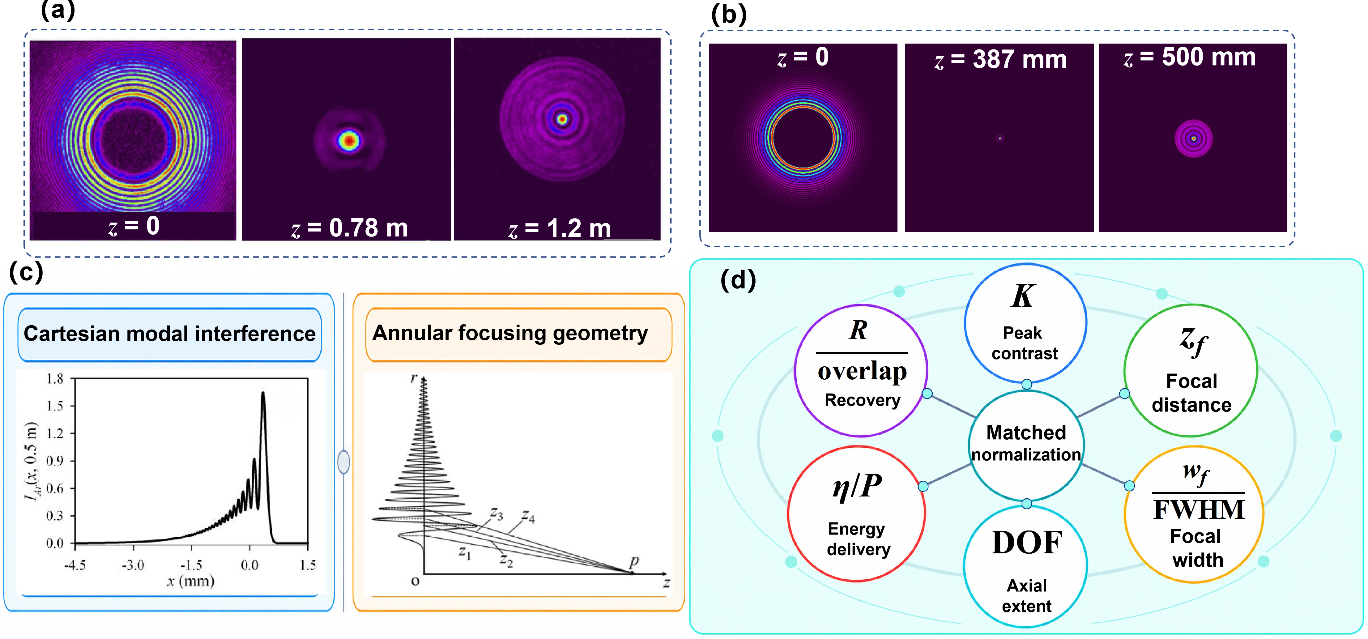
Figure 3. Propagation and matched characterization. (a) Measured CAPB evolution at z = 0, 0.78, and 1.2 m. Reproduced from reference[19]. CC BY 4.0; (b) Authors’ simulated recovery after an inner-ring obstruction, shown at z = 0, 387, and 500 mm using the model and parameters[34]; these are not measured recovery images; (c) Illustration of Cartesian coherent redistribution and circular annular focusing. Reproduced from reference[19,33]. CC BY 4.0; (d) Non-quantitative map of complementary metrics requiring declared normalization and matched resources. CAPB: circular Airyprime beam.
The magnitude and propagation distance of this redistribution depend strongly on the finite-energy parameters. Reducing the exponential apodization extends the oscillatory tail and can increase the source-peak-normalized maximum, whereas w0 primarily rescales the transverse and longitudinal dimensions in the ideal symmetric model[33]. For a = 0.1, w0 = 0.1 mm, and λ = 532 nm, the reported maximum is approximately 1.19 for one Cartesian coordinate and approximately 1.42 for the complete symmetric two-dimensional field, both near z = 0.579 m. The latter follows from the separable two-dimensional construction and should not be interpreted as an independent competing measurement. Likewise, the reported disappearance of the enhancement above a about 0.125 is a model- and normalization-dependent boundary rather than a universal Airyprime threshold.
Optical experiments reproduced the evolution of the complete Cartesian field for selected apodizations and transverse scales, supporting the predicted peak evolution without separately measuring the analytical components in Equations (9)-(11)[33]. Additional phase modulation and higher derivative orders modify this evolution[28,35], but these are controlled extensions rather than part of the intrinsic unmodulated mechanism. The circular Airyprime branch requires a different description because its energy is organized radially rather than through Cartesian separability.
3.2 Circular caustics, derivative order, and energy redistribution
For circular Airy derivative beams, the relevant propagation picture is radial. Their scalar paraxial evolution is described by a Fresnel-Hankel integral in which each source annulus contributes a complex amplitude weighted by the radial measure ρdρ[19]. The propagated intensity is therefore determined by the coherent sum of annular contributions rather than by the addition of independently propagated ring intensities. As the field evolves, the ring structure contracts toward the axis and forms a pronounced caustic-like concentration. This behavior has been observed experimentally for first-order circular Airy derivative fields in free space and under controlled perturbations[19,34,36].
The strong axial concentration can be understood qualitatively through the phase organization of the radial oscillations. Adjacent Airy-derived rings alternate in sign, while their optical paths to a prospective axial focus differ. For the tested beam parameters, the propagation-phase differences can approximately compensate the alternating source phases so that several rings reinforce the field near the focus[19,37]. This picture has often been described as Fresnel-zone-plate-like. The analogy is useful, but should not be taken literally: the source is not a binary zone plate, the rings do not carry equal optical power, and geometrical path differences alone do not constitute a complete decomposition of the transported energy. The circular mechanism is therefore distinct from the Cartesian decomposition of Equations (9)-(11), even though both ultimately involve coherent redistribution of a finite optical field.
Derivative order changes the radial amplitude distribution, sign sequence, and amount of appreciable peripheral support. Under the nominal conditions a = 0.1, r0 = 1 mm, w0 = 0.1 mm, and λ = 532 nm the measured autofocusing factors were K = 323.5 for the CAPB and K = 46.8 for the corresponding CAB, giving a within-study ratio of approximately 6.91[19]. This provides direct experimental evidence that the n = 1 derivative structure can strongly enhance the peak contrast relative to the matched n = 0 source. The ratio, however, is a comparison of K, not of equal-power focusing efficiency. Moreover, the numerical derivative-order sweep in the same study gives still larger K values for n = 2 and n = 3 under its adopted normalization. The first-order field should therefore be regarded as an experimentally established Airyprime member, not as a universal optimum of the derivative hierarchy.
Geometry introduces a second level of optimization. Changing r0/w0 modifies the number and location of contributing rings, their relative propagation phases, the focal distance, and the transverse spectrum. For example, an n = 1 parameter sweep showed that increasing the normalized radius beyond the value that maximized K could continue to reduce the focal full width at half maximum (FWHM) even while K declined[37]. Thus the radius associated with the strongest peak contrast need not coincide with that producing the narrowest focal spot. This already indicates that abrupt autofocusing cannot be described by a single optimum parameter or a single merit function.
3.3 Peripheral rings, obstruction, and self-healing
Obstruction experiments make the role of the radial structure particularly clear, but they also show why self-healing should not be treated as a binary property. Different measurements probe different aspects of recovery. Morphological recovery concerns similarity of the transverse intensity distribution; normalized intensity overlap quantifies that similarity within a specified window; K recovery measures restoration of source-normalized peak contrast; and absolute focal-intensity recovery requires a common incident-power reference. Recovery of focal position and recovery of an actual optical function constitute still further criteria. A normalized overlap can therefore approach unity even when substantial optical power has been removed and the focal intensity has not recovered[34,36].
The authors’ simulated recovery sequence in Figure 3b illustrates propagation after an inner-ring obstruction; it is distinct from the published experimental evidence discussed below. The distinction between retained regions is evident when different radial regions are blocked. In one experiment, an inner obstruction that retained the field outside r = 1.32 mm transmitted approximately 81.6% of the initial power and preserved a pronounced focus with high morphological overlap, although K decreased. The complementary truncation retained only about 18.4% of the initial power; the subsequent field recovered part of the ring morphology but developed a much weaker and displaced focus[34]. Because the two masks remove very different amounts of power, this experiment alone cannot separate spatial location from resource loss. Matched fractional-power truncations nevertheless produced different responses for inner and outer removal, providing stronger evidence that the location of the retained radial support matters in addition to the remaining power[38]. This result also illustrates why visually weak peripheral rings can remain important: the power carried by an annulus depends on its integrated area, not only on its local peak intensity.
Phase perturbations probe a different notion of robustness. Circular first-order fields have retained recognizable autofocusing behavior in experiments using spatial-light modulator (SLM)-emulated complex or turbulent media, although K, focal position, axial extent, and pattern similarity deteriorate to different degrees[36,38]. Some propagated-field quantities were measured experimentally, whereas large statistical ensembles for overlap or scintillation were obtained numerically. The results therefore support perturbation-dependent robustness rather than unconditional invariance. They also reinforce a broader lesson: morphological recovery, peak recovery, statistical stability, and functional recovery are different questions. The available measurements establish optical-field reconstruction and autofocusing resilience, but not recovery of an end-use trapping or communication function.
3.4 Benchmarking autofocusing: K, focal distance, width, DOF, and efficiency
The autofocusing factor remains a useful descriptor because it quantifies the increase in peak intensity relative to the source plane. A general tracked-peak definition is
Axisymmetric studies may instead use the on-axis focal intensity, so the adopted convention should always be stated when the symmetry of the field can change[19,34,39]. Because multiplying the entire field by a constant scales both numerator and denominator equally, K is insensitive to overall amplitude normalization for an unchanged field shape. This is advantageous for characterizing peak contrast, but it also means that K does not measure total incident power, transmitted power, focal power fraction, generation efficiency, or system throughput.
The remaining focal observables describe complementary aspects of performance. The focal distance states where the selected axial maximum occurs. Transverse FWHM and full 1/e2 width use different intensity thresholds and should not be interchanged for non-Gaussian focal profiles. Axial half-maximum width, on-axis-intensity depth of focus, and spot-size-based depth of focus likewise describe different longitudinal properties. Focusing efficiency depends on the selected power denominator and focal integration region, while a recovery metric depends on the obstruction, analysis window, and recovered observable[36,39]. Table 2 summarizes the definitions and minimum comparison conditions required for these quantities.
Table 2. Definitions and comparison conditions for principal Airyprime performance metrics. Each quantity must be reported together with its normalization, threshold, integration region, and resource constraint.
| Metric | Definition | Meaning | Comparison requirements |
| Autofocusing Kf | K(z) = Ipeak(z)/Ipeak(0); Kf = maxz K(z) | Source-relative peak contrast | Peak convention; normalization; aperture; λ; input power |
| Focal distance zf | Position of the selected intensity maximum | Focus location | Peak rule; origin; λ; source scale; optical system |
| Focal width wf | FWHM or full 1/e2 width of a stated cut | Transverse confinement | Threshold; cut; magnification; NA; sampling |
| Axial extent/DOF | Interval meeting a stated intensity or width criterion | Longitudinal persistence | Threshold; reference; focus rule; axial sampling |
| Focusing efficiency η | Focal-region power/incident or transmitted power | Useful power fraction | Denominator; region; aperture; losses; calibration |
| Recovery R | Declared overlap or recovery ratio after obstruction | Recovery of a specified observable | Removed power; mask; distance; window; observable |
Controlled asymmetry provides a useful example of this multi-objective character. Two distinct operating regimes were reported experimentally: one extended the DOF by as much as 400% while increasing the autofocusing response by approximately 32% and producing a focal spot of about 32 μm; another increased the autofocusing factor by as much as 193%, with a focal spot of approximately 56 μm and little change in DOF[39]. These improvements correspond to different source settings and cannot be combined into a single operating point. Numerical analysis in the same study further indicates that peak efficiency does not necessarily track either the largest K or the longest axial extent. Similarly, radius optimization can produce a narrower focal FWHM while reducing K[37]. These examples demonstrate competing or partially independent objectives, rather than a universal theorem that improving one quantity must always degrade another.
A more informative comparison of Airyprime autofocusing reports a vector of observables at a defined operating point rather than ranking fields by K alone. At minimum, the source geometry and normalization, wavelength, physical aperture, incident and transmitted power, focal-distance criterion, transverse-width definition, axial-extent definition, focal integration region, sidelobe measure, robustness metric, and uncertainty should be specified. Equal source peak, equal incident power, and equal transmitted power are different resource constraints. Conventional Airy studies provide precedents for propagation in water and abrupt autofocusing[40-42]. Multiphoton polymerization and symmetric-beam propagation provide additional application and propagation baselines[43,44]. Additional studies of recovery and alternative autofocusing geometries show why the selected metric and resource constraint must be declared[45-47]. Table 3 records representative Airyprime studies in this format and marks unavailable values as NR.
Table 3. Representative Airyprime benchmarking records. Each row identifies the source and reports launch conditions, focal or recovery metrics, power or efficiency, evidence type, and uncertainty. NR denotes not reported in a cross-study-comparable form. This is an evidence-gap audit, not a ranking.
| Study and source | Normalization and launch conditions | Reported focal/recovery metrics | Power, evidence and uncertainty |
| Dan et al.[33] Cartesian Airyprime | Source peak = 1; λ = 532 nm; aperture/NA: NR. a = 0.1; w0 = 0.1 mm. | 2D peak 1.42 at z = 0.579 m; width/DOF: NR. | Input/transmitted power and efficiency: NR. A + N + E. Uncertainty: NR. |
| Zang et al.[19] CAPB vs CAB | K = Ifm/I0m; same r0, w0, a, not equal power. λ = 532 nm; SLM 14.4 × 8 mm; effective aperture/NA: NR. | r0 = 1 mm, w0 = 0.1 mm, a = 0.1: zf ≈ 0.78 m; FWHM 67 vs 73 μm; measured K 323.5 vs 46.8. | Power/efficiency: NR. N + E. K experiment-theory difference ≈ 9.4%; individual error bars: NR. |
| Kumari et al.[34] Blocked first-order CADB | K and normalized overlap; ideal field reference. λ = 1,064 nm; binary masks; clear aperture/NA: NR. | Recovery for inner, outer and sectorial masks; maximum overlap near zaf. | Representative complementary transmissions: 81.6%/18.4%; efficiency: NR. N + E; qualitative agreement; confidence intervals: NR. |
| He et al.[37] CAPB radius control | Source-peak-normalized K; λ = 532 nm; SLM generation; effective aperture/NA: NR. | K up to 1,822.49 at a = 0.05, R0 = 26; K and FWHM optima differ. | Power/efficiency: NR. N + E. Uncertainty: NR. |
| Kumari and Pal[39] Asymmetric CADB | Within-study symmetric baseline; λ and aperture/NA: NR. | Setting 1: DOF + 400%, K + 32%, spot ≈ 32 μm. Setting 2: K +193%, spot ≈ 56 μm; DOF nearly unchanged. | Transmitted power/absolute efficiency: NR. N + E. Quantitative error bars: NR. |
E: optical-field experiment; N: numerical simulation; A: analytical model; CAPB: circular Airyprime beam; CAB: circular Airy beam; SLM: spatial light modulator; CADB: circular Airy derivative beams.
Cross-family comparisons must use the same discipline. Conventional circular and multifocus Airy fields, as well as pre-engineered caustic beams, demonstrate that focal multiplicity and abrupt focusing are not unique to Airyprime sources[48-50]. Vortex, polycyclic, swallowtail, and circular Pearcey-Airy architectures provide additional autofocusing and trapping comparators[51-54]. Vector autofocusing Airy fields with polarization singularities provide an independent comparator for propagation stability and self-recovery[55]. These studies provide comparison methods and baselines; they are not counted as Airyprime evidence unless an Airyprime field was explicitly analyzed. Geometrical-optics descriptions and nonparaxial abruptly autofocusing constructions further show why propagation approximation and aperture must be stated[56,57].
4. Engineering and Manipulation of Airyprime Fields
4.1 Source amplitude and phase-gradient engineering
Once the intrinsic propagation behavior has been established, Airyprime-field engineering can be viewed as the deliberate modification of a limited set of physical degrees of freedom rather than the creation of a new beam family for every variation. At the source plane, the first distinction is between amplitude geometry and phase control. Apodization, source radius, transverse scale, envelope, and aperture determine how much of the field is launched and how its power is distributed spatially. Changing these quantities can therefore modify the focal distance, peak contrast, focal width, and the peripheral support available for subsequent propagation. As discussed in Section 3, the radius that maximizes K need not minimize the focal width[37]. Such changes may also alter the total incident power, so comparisons based only on equal source-peak normalization should be interpreted as comparisons of field structure rather than equal-resource performance. Figure 4a illustrates source-radius control through the authors’ simulations, whereas Figure 4b,d retain measured propagation examples. Figure 4c illustrates the separate role of Fourier-spectrum filtering. Representative operation-to-observable relationships are compared in Table 4.
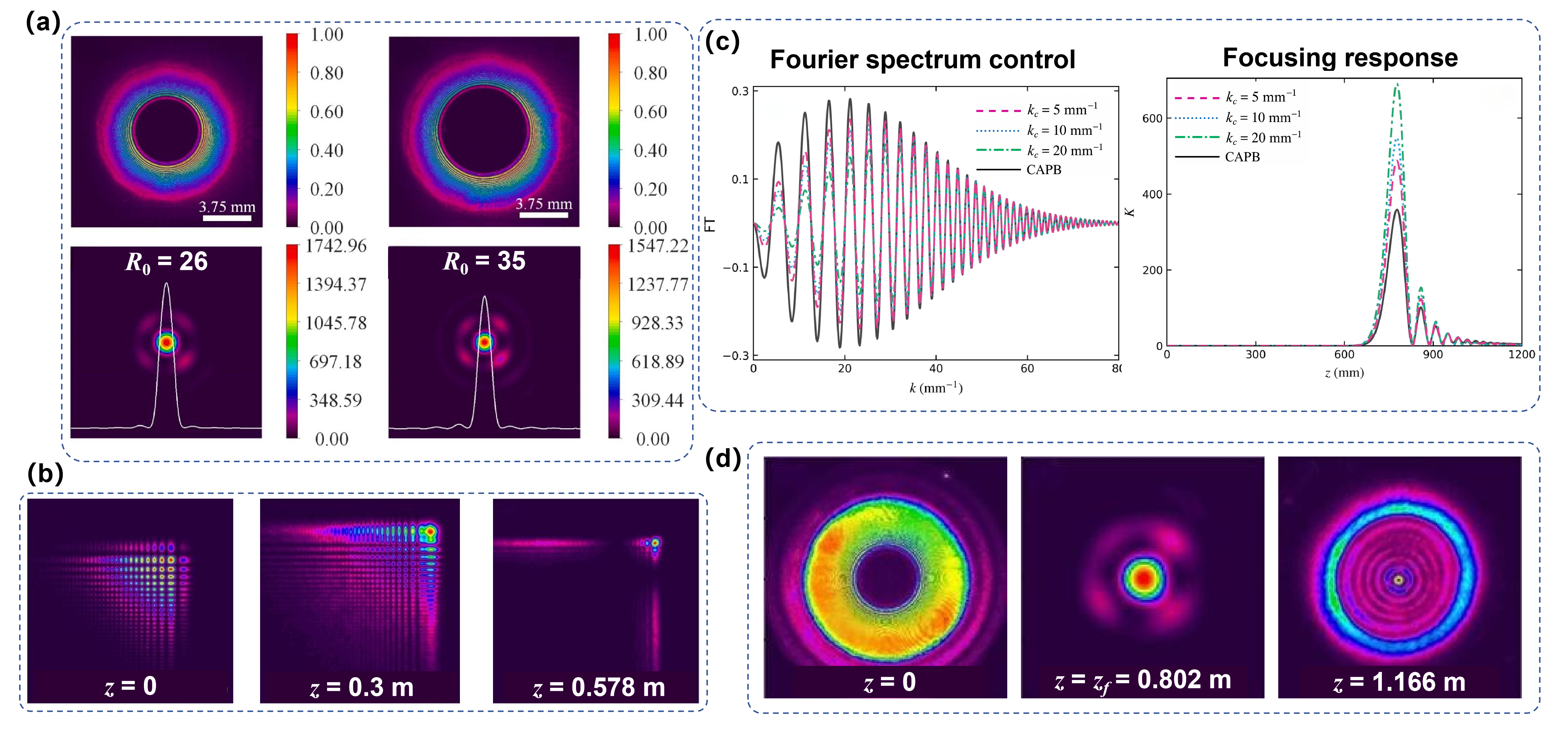
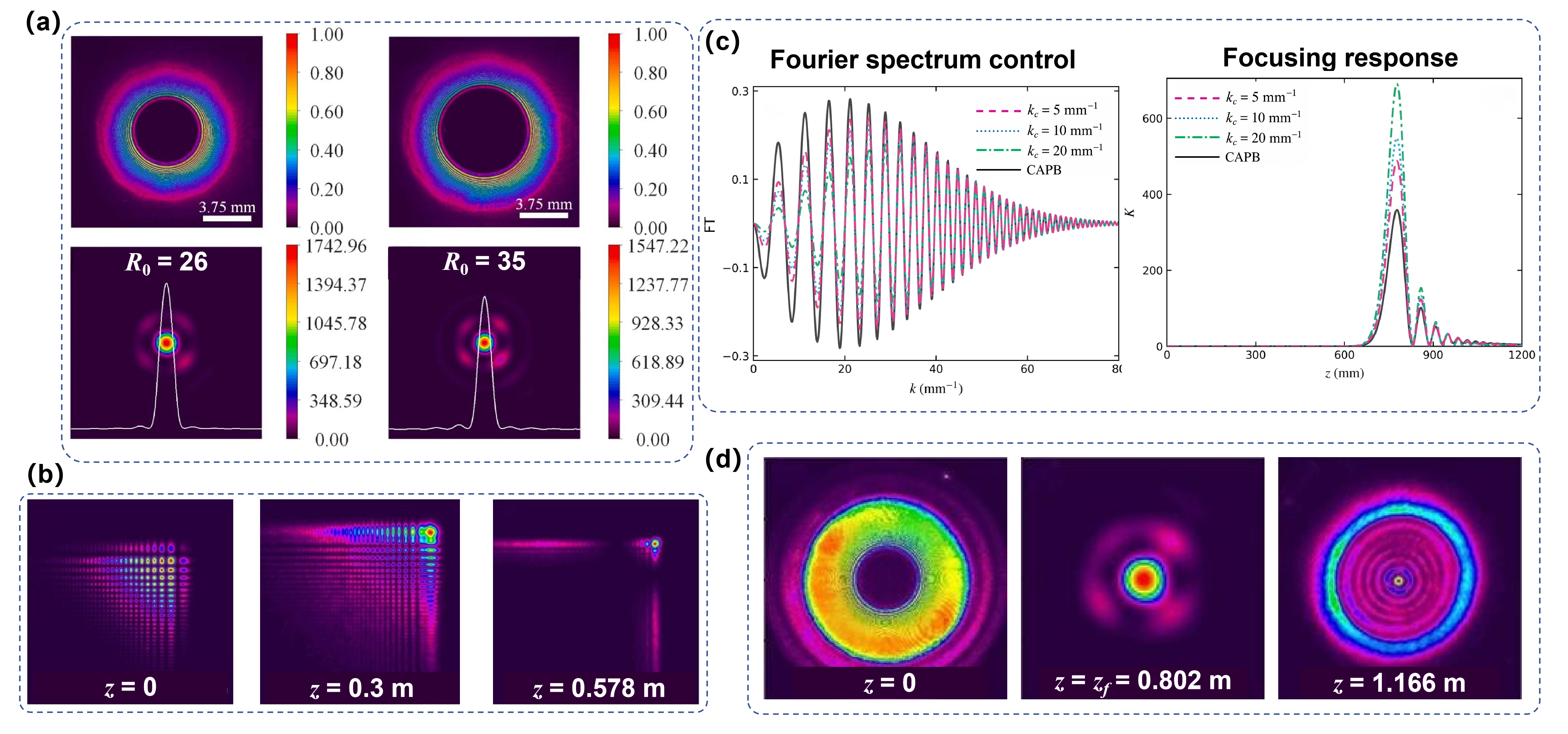
Figure 4. Operation-based field engineering. (a) Authors’ simulations of source-geometry control for dimensionless radii R0 = 26 and 35 using the model and parameters[37]; (b) Measured linearly chirped Cartesian propagation. Reproduced from reference[35]. CC BY 4.0; (c) Fourier-spectrum filtering and the resulting focal response, independently calculated and plotted by the authors using Eqs. (1), (2), (7), and (8) and the parameters[58]. No image or traced curve from that publication is reproduced. The plotted Fourier amplitude is scaled by a common factor of 10 for display, while K is normalized to each field’s own initial peak intensity; (d) Measured circularly transformed Airyprime evolution, adapted from reference[29]. Reproduced from reference[29]. CC BY 4.0. Newly calculated panels illustrate the reported models rather than supplying additional experimental evidence. Axes and normalizations are specific to each example.
Table 4. Control operations and measurable consequences. Source-amplitude and phase controls are distinguished from Fourier-plane filtering, downstream lens mapping, coordinate transformations, and coherent superposition. The rows summarize controlled observables rather than a performance ranking. Optical-field control alone does not establish an application.
| Operation | Controlled variable | Implementation | Observables |
| Apodization/radius/aperture | Amplitude and support | Finite-energy truncation; source-radius selection | zf, K, wf, peripheral support |
| Phase gradients | Source phase | Cartesian linear phase; radial chirp | Trajectory, zf, K, axial extent |
| Filtering/lens mapping | Spectrum or optical system | High-pass filter; downstream lens | Focal response, dual-focus positions |
| Asymmetry/ellipticity | Amplitude, phase, symmetry | Complex shifts; unequal scaling | DOF, K, focal morphology |
| Topology | Azimuthal phase; singularities | Vortex phase; nonlinear phase; polynomial factors | Rotation, lobes, singularities, calculated OAM |
| Coordinate transformation | Coordinate geometry | Angular integration; conditional Airy transform | Circular morphology; mapped field |
| Coherent arrays | Position, number, relative phase | Single/dual rings; square/elliptical arrays | Focus positions; uniformity; line/ring patterns |
| Hybrid envelope | Radial support and caustics | Gaussian, Bessel or Pearcey weighting | Axial extent; bottle shape; K/wf balance |
| Generated lattices | Coherent superposition | Airyprime-generated lattice fields | Intensity pattern and geometry |
OAM: orbital angular momentum.
Phase gradients provide a more direct means of steering or reshaping propagation without necessarily changing the ideal source intensity. For separable Cartesian Airyprime fields, a linear phase primarily shifts the transverse spatial frequency and redirects the trajectory, whereas a quadratic phase modifies the wavefront curvature and hence the axial evolution of the peak[35]. Optical experiments reproduce both forms of control. The distinction matters because the two operations influence different aspects of the propagated field: the linear term mainly changes trajectory, while curvature can alter the distance and axial interval over which peak enhancement develops. Their behavior should not be reduced to a single generic “chirp” rule.
Radial phase modulation acts differently because the circular source is organized through annular contributions. A linear radial chirp such as exp [ic1(r0-r)/w0] changes the relative phase of the rings while preserving the ideal source intensity, whereas a radial quadratic term introduces an additional curvature analogous to a source-encoded lens[59,60]. The resulting variations of autofocusing factor and focal distance depend jointly on chirp sign, apodization, and normalized source radius. Reported parameter maps contain regimes in which the two observables increase together, change in opposite directions, or vary non-monotonically. Consequently, no geometry-independent statement such as “positive chirp shortens the focal distance” is generally justified. Selected radial-phase cases have been verified experimentally[59], whereas broader sign and geometry maps remain primarily theoretical or numerical[60]. The same phase operation can also be spatially partitioned or composed with other architectures. Assigning different radial chirps to complementary angular sectors produces separate axial responses whose relative strengths can be adjusted through the sector allocation[61]. Likewise, imposing phase gradients on individual Cartesian Airyprime beamlets before coherent ring summation changes the collective focal position, peak contrast, and width. These examples illustrate the modular nature of Airyprime engineering: a phase operation may act on a single field, on selected regions of that field, or on the elements of a coherent array without constituting a new foundational source construction.
4.2 Lens, Fourier-space, and asymmetric control
Control can also be imposed after the source has been formed. Fourier-plane filtering provides a particularly clear example because it acts directly on spectral amplitude rather than on source phase. A high-pass spatial-frequency filter can change the frequency content contributing to CAPB propagation and thereby shift the focus and modify K, as demonstrated experimentally in a 4f system[58]. The associated increase or decrease in source-normalized peak contrast must, however, be distinguished from system efficiency: spectral components rejected by the filter, finite apertures, and spatial resolution all contribute to the physical throughput. A larger K after filtering therefore does not by itself imply that more incident optical power has been delivered to the focus.
A downstream lens represents another system-level operation. Rather than defining a new “lens-transformed Airyprime beam,” the lens maps an already evolved CAPB through an additional optical transfer system. Changing its longitudinal position modifies the locations and relative strengths of the two physical focal responses associated with the real and virtual Janus structure, and these changes have been observed experimentally[62]. This differs from encoding quadratic phase directly in the source because the field reaching the lens has already accumulated propagation-dependent phase and amplitude. Although optical forces have been calculated for the resulting focal regions, the reported field measurements do not themselves constitute an experimental trapping demonstration.
Breaking source symmetry provides a complementary route to multi-objective control. Coherent combinations of circular derivative fields with complex transverse shifts modify both amplitude and phase and generate distinct operating regimes emphasizing axial extent, peak contrast, or focal morphology[39]. The regimes favoring large DOF and large K occur at different control settings, as discussed in Section 3. Elliptical coordinate scaling likewise breaks rotational symmetry and can reshape a circular focal distribution into extended or line-like structures[63]. These transformations are more naturally interpreted as asymmetric field engineering than as additional Airyprime families.
4.3 Topological structuring, coordinate transformations, and hybridization
Section 2.3 defined coordinate transformations and coherent superpositions as conditional relationships among source constructions. The present section considers their engineering consequences and does not reclassify them as source equivalences. Topological structuring itself spans several operations. A unit-modulus azimuthal phase changes the phase gradient while preserving the ideal source intensity; a displaced polynomial singularity changes both magnitude and phase. Nonlinear and composite azimuthal phases generate rotating or multi-lobed focal patterns[25,64], whereas polynomial factors also modify source support and singularity position[65]. Figure 5c shows the authors’ simulations of vortex-loaded CAPB focal patterns for l = 1 and 3 using the model and parameters of Ref.[65]. These panels illustrate the model rather than reproducing its experimental images. Vortex-pair modulation provides a separate circular Airyprime autofocusing example[66], but it does not supply the model for Figure 5c.
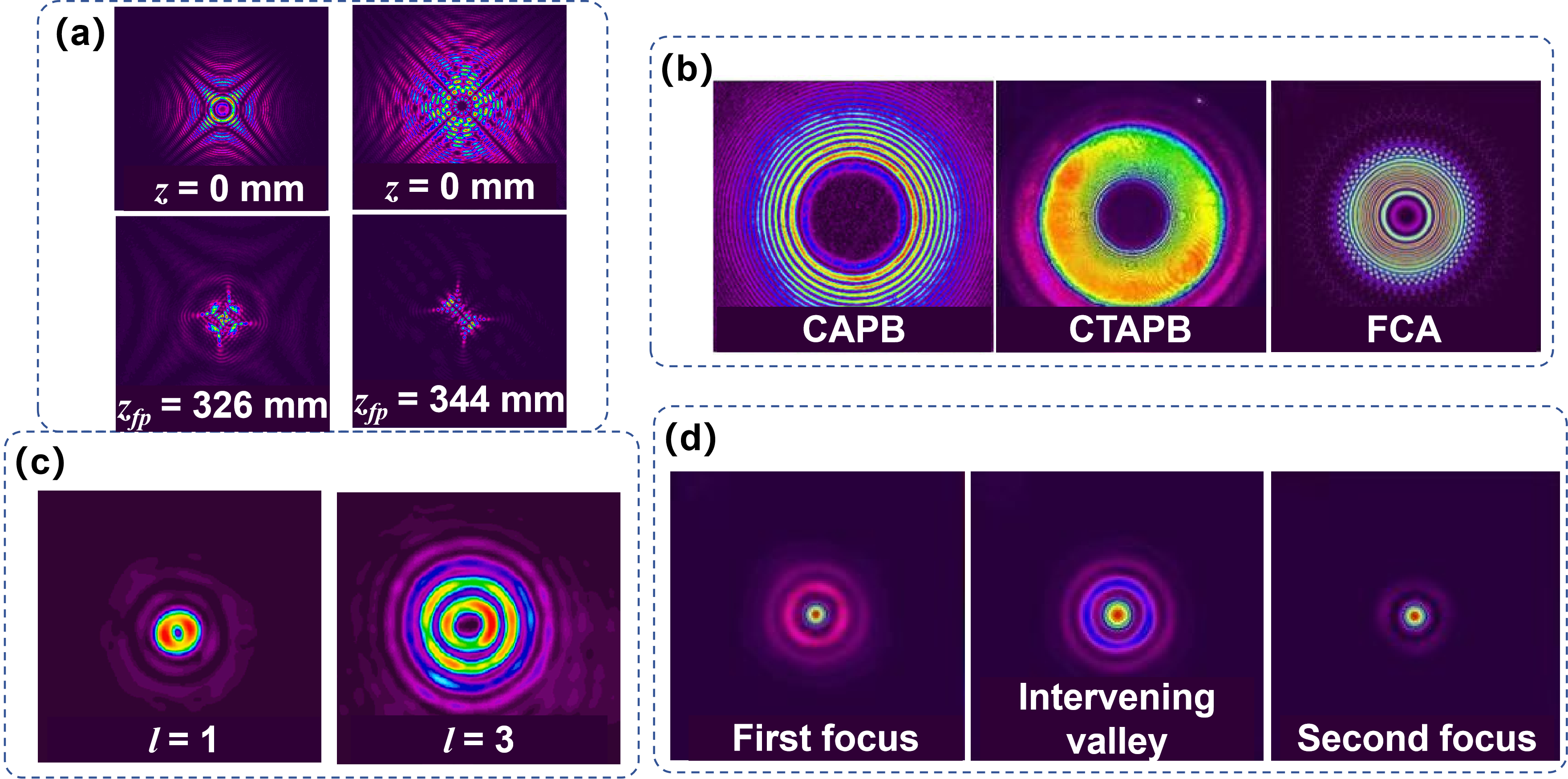
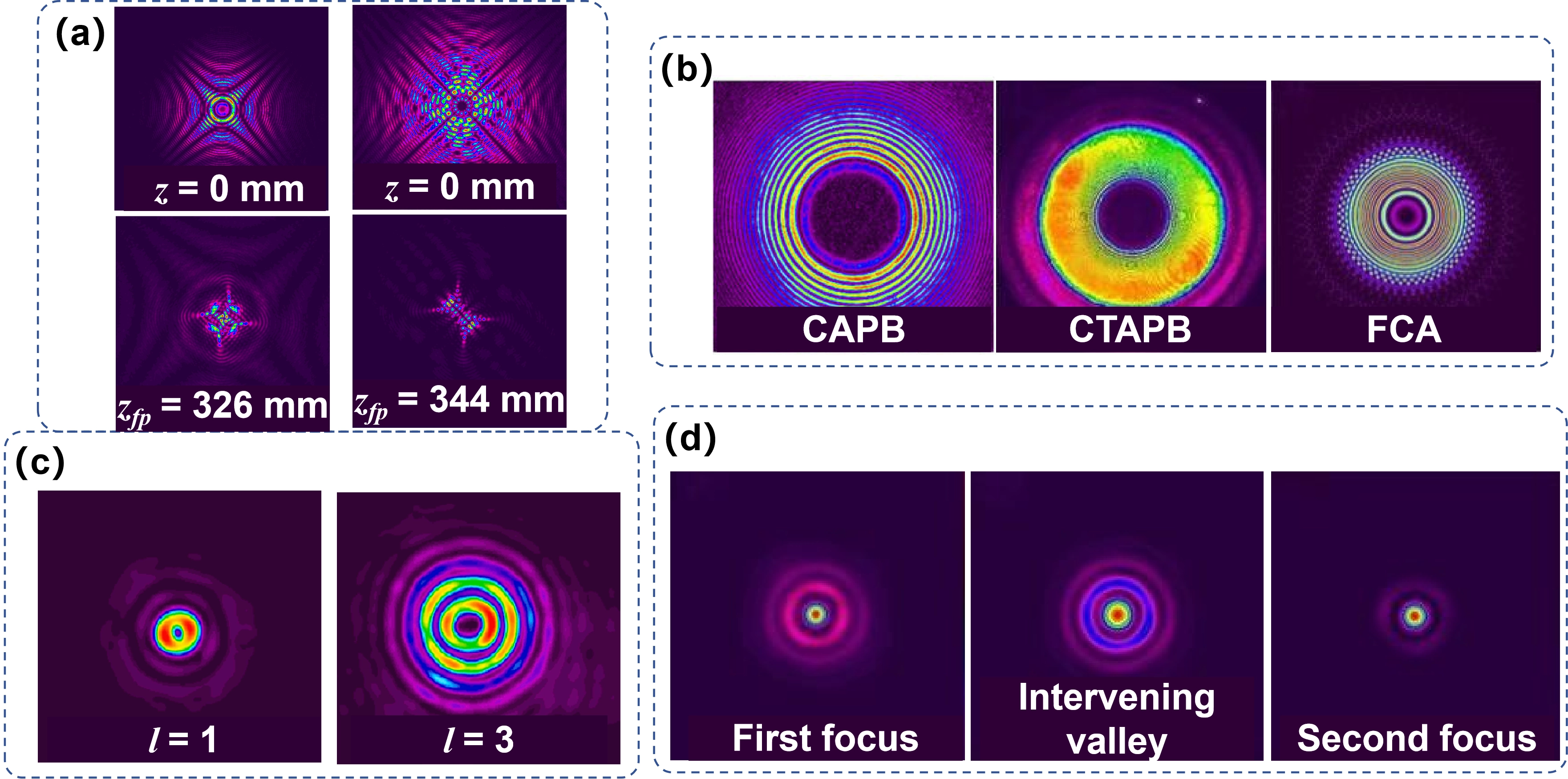
Figure 5. Structured Airyprime architectures. (a) Authors’ simulated source and focal lattice patterns using the model and parameters[67]; (b) Source patterns of the directly prescribed radial CAPB, continuously transformed CTAPB, and FCA[30], from left to right. Reproduced from references[19,29]. CC BY 4.0; (c) Authors’ simulated focal patterns for vortex charges l = 1 and 3 using the model and parameters[65]; these are not measured focal patterns; (d) First focus, intervening valley, and second focus of a juxtaposed double-ring array. Reproduced from reference[68]. CC BY 4.0. Each example has its own normalization; the constructions in (b) are not mathematically identical. CAPB: circular Airyprime beam; CTAPB: circularly transformed Airyprime beam; FCA: finite coherent ring array.
The orbital angular momentum (OAM) terminology also requires care. A topological charge may denote local phase winding, a coefficient in a nonlinear phase function, or a discrete phase increment between array elements; none alone establishes that the field is a single OAM eigenmode. Airyprime studies calculate OAM density, spiral spectra, singularities, or energy flow, whereas experiments more often record intensity evolution, pattern rotation, singularity-dependent morphology, and particle motion[25,64,67,69]. Calculated distributions must remain distinct from direct experimental modal measurements. Topology nevertheless provides a genuine engineering degree of freedom, and selected structured fields have supported particle manipulation[27,64]; Section 7 assesses their application-level performance.
Coordinate transformations constitute a separate class of operation. Continuous angular integration of displaced and rotated Cartesian Airyprime fields produces the circularly transformed Airyprime beam, whose source remains mathematically distinct from the directly prescribed radial CAPB[29]. A discrete ring array can approximate aspects of this angular construction when its sampling, weights, phases, and geometry are appropriately matched, but a finite coherent sum is not identical to the continuous integral. Likewise, the later Airy transformation of an Airyprime input establishes conditional forward mappings to coordinate-wise combinations of Airy and Airyprime contributions, including special Hermite-Gaussian-type outputs for selected transformation parameters[31]. These relations expand the available transformation toolbox without establishing a reversible Airy-Airyprime cycle.
Hybridization introduces additional source support or spectral structure rather than a new Airyprime derivative principle. Gaussian weighting can reshape finite support and facilitate coherent architectures; Bessel modulation introduces another radial spectral degree of freedom and can balance focal peak against longitudinal extent; and Pearcey factors add a different caustic geometry[68,70,71]. The experimentally generated circular Pearcey-Airyprime field provides independent evidence that such hybridization can preserve controllable autofocusing[71]. Other Airyprime-Gaussian configurations containing paired singularities have mainly been studied numerically in high-NA, vectorial, or spatiotemporal settings[26,72,73]. Their importance lies in the additional controllable degrees of freedom they provide, while the corresponding multidimensional and vectorial regimes are treated separately in Section 6.
4.4 Coherent arrays, generated lattices, and collective interference
The source relationships of continuous angular integration and finite coherent sampling were established in Section 2.3. Here, coherent arrays are treated as engineering architectures whose element number, position, orientation, and relative phase control measurable focal observables. Ring arrays and four-beamlet square arrays reorganize energy into collective focal structures and modify focal position and width[30,74]. Experiments demonstrate the four-beamlet field, whereas convergence with increasing beamlet number has mainly been examined numerically. Any increase in focal intensity must be interpreted together with total incident power, because adding beamlets also changes the launched resource.
Increasing the number of beamlets illustrates the distinction between discrete architecture and continuous transformation. For a fixed ring geometry, sufficiently dense angular sampling can make the calculated focal response increasingly insensitive to further beamlets[30]. Such convergence is useful for implementation and for understanding how a discrete superposition approaches an angularly continuous construction, but its numerical threshold depends on the source parameters, geometry, normalization, and chosen metric. It should therefore not be interpreted as a universal saturation law, nor as evidence that a finite array becomes mathematically identical to the continuous circular transformation[29].
More elaborate architecture combines coherent geometry with other control operations. Dual rings can place energy at separated axial positions and form multiple foci or dark intervals; elliptical placement and Gaussian weighting can generate extended or line-like distributions; and vortex or charge-dependent phase factors can redistribute energy among rotating lobes and multiple focal sites[27,68,75,76]. Experiments support many of these field morphologies, and selected charge-tailored arrays have also produced trapping-compatible focal arrangements[27]. Their principal advantage is programmability rather than universally greater efficiency: distributing energy among additional sites generally changes the power available to each, while definitions of uniformity and selected-region efficiency remain specific to individual studies.
At the collective limit, coherent superposition can generate dynamic and multilayer optical-lattice patterns[67,69]. The published studies report measured optical fields; Figure 5a instead presents the authors’ corresponding numerical illustrations. Neither a simulated nor a measured intensity lattice alone demonstrates atomic trapping, quantum processing, or fabrication. Generated optical lattices must also be distinguished from external periodic or parity-time-symmetric media through which a field propagates. Conventional Airy and related beams provide precedents for chirped, vortex, and bottle-field control[77-79]. Quantum-state and trajectory analyses supply complementary vortex-beam context[80,81]. Ring, astigmatic, and elliptical architectures supply further comparison methods[82-84]. Elliptical-vortex studies extend these geometry and topology baselines[85,86]. Fourier-space generation, Pearcey bottles, and Airy-vortex experiments provide operation-level precedents[87-89]. Pearcey recovery and Airy-vortex dynamics add distinct propagation comparisons[90,91]. None of these conventional studies establishes an Airyprime result. Section 5 therefore turns from source engineering to the response of a specified Airyprime field under a specified propagation environment. Conventional dual Airy beams provide a separate coherent-superposition precedent, rather than an Airyprime source definition[92].
5. Propagation in Complex Optical Environments
5.1 Turbulence and complex-media robustness: Branch-specific evidence
Changing the propagation environment shifts the discussion from the intrinsic dynamics of Section 3 and the source engineering of Section 4 to the response of a specified field under a specified perturbation. In this setting, environmental resilience is meaningful only when the Airyprime branch, perturbation model, observable, and evidence maturity are stated together. In particular, a random phase pattern displayed on a SLM represents a laboratory thin-screen perturbation; it is not equivalent to continuous refractive-index fluctuations along a distributed atmospheric path. Figure 6 separates the laboratory single-screen method from multiple-screen, fractional, nonlinear, and externally prescribed-medium models. Its newly drawn or simulated illustrations do not add experimental evidence to those model-only categories. Representative propagation models and their evidence limits are compared in Table 5.
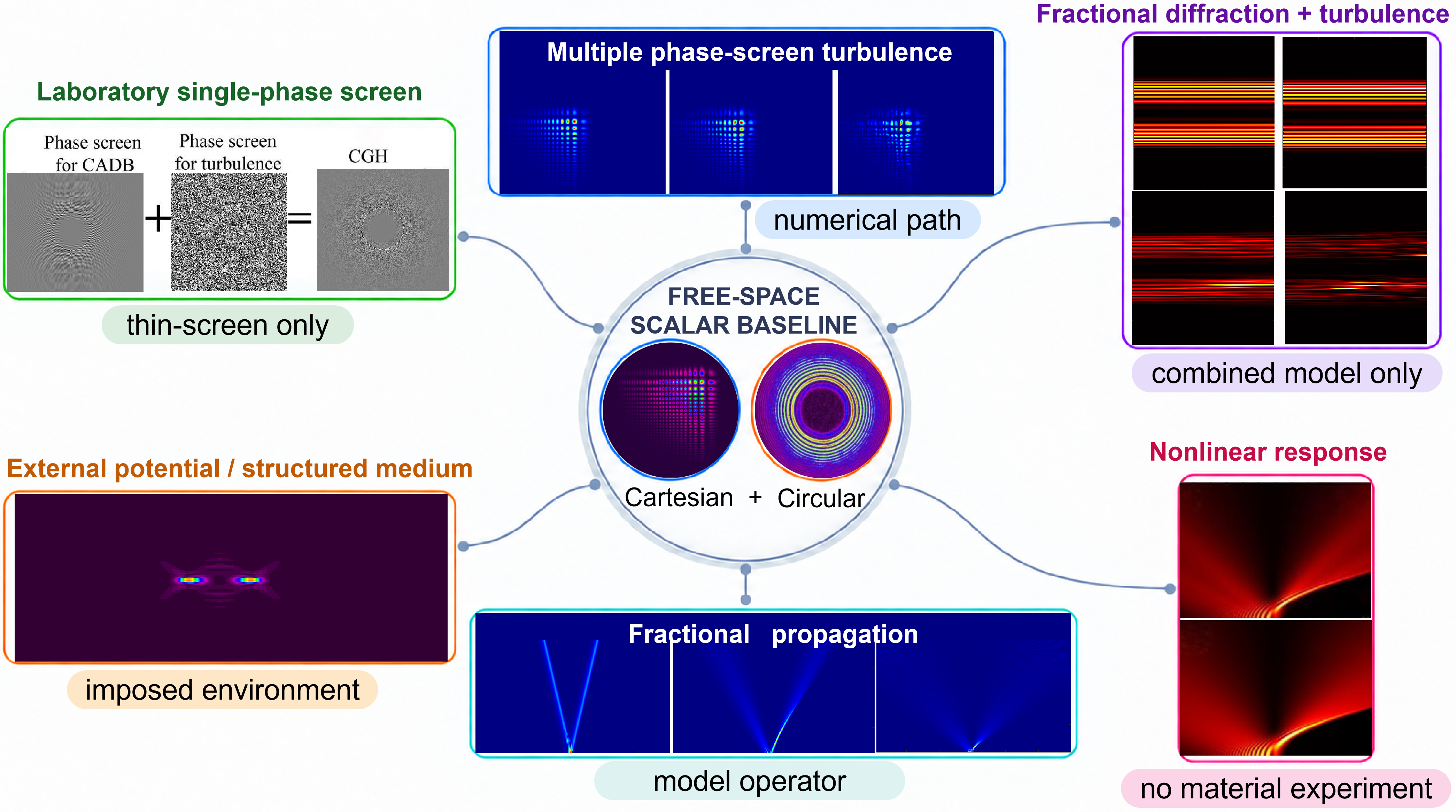
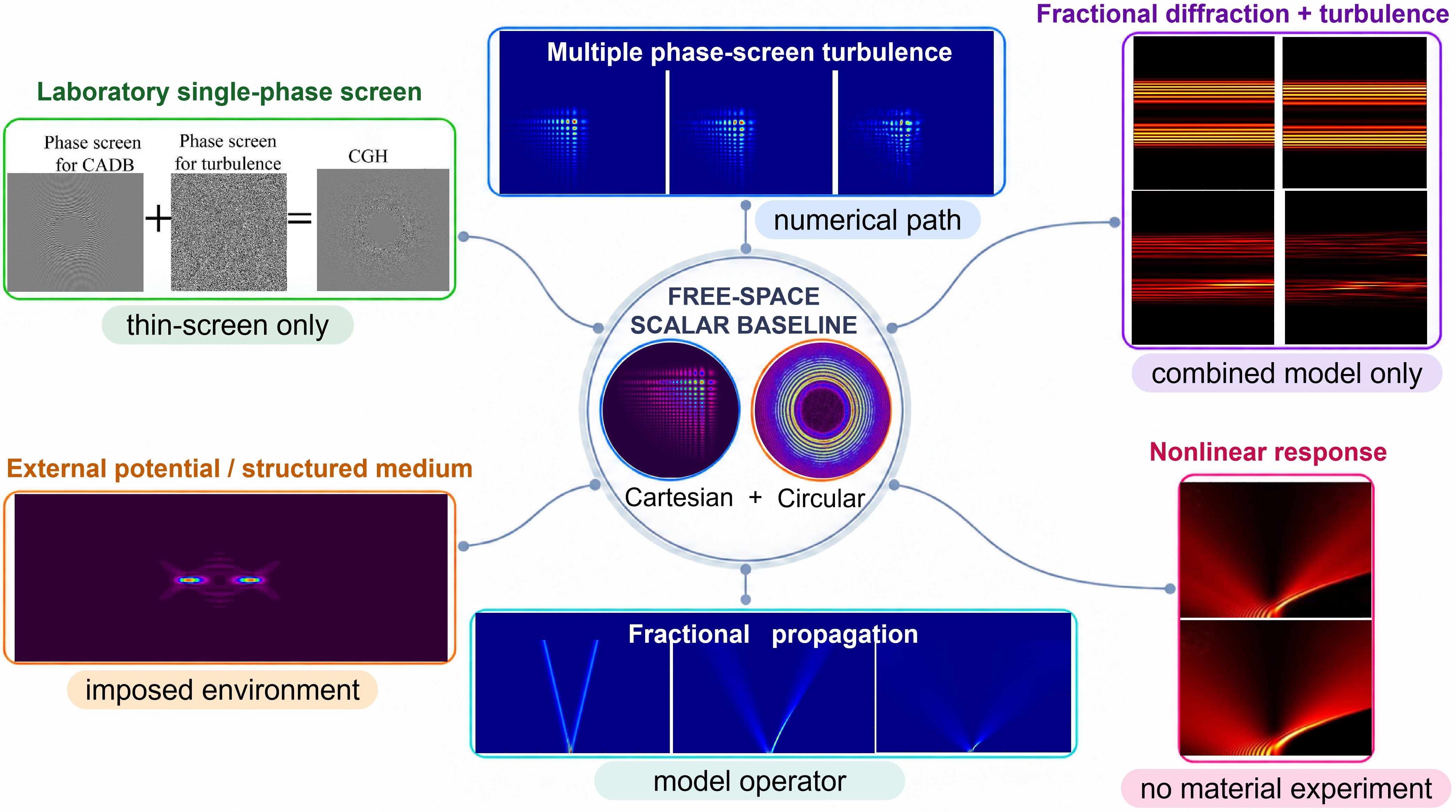
Figure 6. Propagation environments and their evidence limits relative to the free-space scalar baseline. The central Cartesian and circular source fields, respectively. Reproduced from references[19,33]. CC BY 4.0. Clockwise from the upper left, the surrounding examples show a single-phase-screen encoding schematic drawn by the authors; multiple-phase-screen turbulence simulations[21]; combined fractional-diffraction and turbulence simulations[93]; local and weakly nonlocal nonlinear propagation[94]; fractional propagation illustrated by the authors; and propagation in an externally prescribed gradient-index medium[95]. The single-screen schematic depicts a laboratory perturbation method, not a measured transmitted field or a distributed atmospheric path. Newly simulated panels illustrate the specified models; neither fractional operators nor prescribed media constitute experimental implementation. The environmental examples use separate scales and are not a common-condition robustness comparison. CADB: circular Airy derivative beams.
Table 5. Propagation models and evidence maturity. Sources are given separately in each row. Laboratory thin-screen measurements are distinguished from distributed-path simulations; nonlinear and fractional calculations do not establish corresponding material experiments. Numerical communication metrics are not end-to-end link demonstrations.
| Model and sources | Branch | Established evidence | Boundary |
| Free space[19,20,28,33] | Cartesian/circular | Branch-specific propagation baselines | Sources are not equivalent; match normalization. |
| Laboratory thin screen[36,38] | CAPB | Measured focus under tested perturbations | Not a distributed atmosphere; calibration incomplete. |
| Multiple screens[21] | Cartesian Airyprime | Numerical turbulence response | No field turbulence experiment or link test. |
| Vortex turbulence[93,96] | Circular vortex fields | Calculated channel and topology effects | BER/capacity calculations are not a link demonstration. |
| Kerr/relaxing response[94,97,98] | Airyprime packets | Predicted nonlinear regimes | Not linear autofocusing; no material experiment. |
| Strong nonlocality[99-102] | Spatial/space-time fields | Analytical/numerical propagation | A peak alone is not a soliton or bullet; no material validation. |
| Fractional operator[103-106] | Circular/Cartesian | Calculated order-dependent propagation | No experimentally implemented Airyprime fractional control. |
| External potentials[95,103,107] Harmonic/parabolic potentials[108,109] | Prescribed input/medium | Modeled operator-dependent reshaping | Not a generated lattice; no corresponding implementation. |
| Chiral/vectorial models[72,73,110,111] | Structured/focused fields | Calculated components and medium response | No vector-field experiment or matched universal gain. |
The strongest experimental evidence presently concerns the circular derivative branch. Laboratory studies of CAPBs under the definition adopted here, used SLM-encoded Kolmogorov- or von Kármán-type phase screens and measured the propagated optical field[36,38]. Under the tested perturbations, a measurable focus survived, but its position, peak-based autofocusing factor K, axial or transverse extent, morphology, and normalized intensity overlap did not remain invariant. These results therefore demonstrate persistence of selected focusing observables in laboratory phase-screen systems, rather than turbulence resistance as a universal property of Airyprime beams.
The circular experiments also show why environmental response cannot be summarized by a single metric. In matched fractional-truncation comparisons, configurations retaining a larger absolute K did not necessarily exhibit smaller relative fluctuations or lower numerically evaluated scintillation[38]. Retained focusing, focal-position stability, width stability, morphological similarity, overlap, and scintillation can consequently rank the same perturbed field differently. Some turbulence-calibration and receiver-dependent quantities cannot be reconstructed uniquely from the reported parameter set. This does not alter the qualitative interpretation of the measured optical trends, but it limits the precision with which those quantities can be compared across studies.
The Cartesian branch has a different evidence profile. Propagation of finite-energy Cartesian Airyprime beams through multiple modified-von-Kármán phase screens has been numerically investigated using beam wander, scintillation, and average bit-error-rate metrics[21]. Related simulations of ring Airyprime vortex fields extend the modeled observables to orbital-angular-momentum purity, channel capacity, and bit error rate (BER)[96], while combined fractional-diffraction and turbulence models explore further conditional behavior[93]. These are numerical channel models: the audited evidence does not establish either a Cartesian Airyprime optical-field turbulence experiment or an Airyprime communication-link demonstration. Circular laboratory evidence and Cartesian numerical evidence must therefore remain distinct.
5.2 Local, nonlocal, and relaxing nonlinear response
Linear Airyprime abrupt autofocusing and nonlinear self-focusing are different physical mechanisms. The former follows from coherent propagation of the structured source, whereas the latter arises from intensity-dependent material response. Numerical nonlinear-Schrödinger models show that generalized Cartesian Airy-derivative fields can fragment into multiple localized structures under a local response, while a tested nonlocal response suppresses fragmentation and supports breathing propagation[94]. Such behavior is attributable to the coupling between derivative-field structure and the chosen nonlinear kernel, not to a universal extension of linear autofocusing.
Circular Airyprime and Airyprime-Gaussian sources have likewise been modeled in Kerr media, where nonlinear self-action combines with imposed source phases to alter trajectories, focal evolution, and morphology[97,98]. Because phase engineering and nonlinear response act simultaneously in these calculations, their contributions should be distinguished when interpreting a displaced focus or localized peak. Terms such as “breathing” or “soliton-like” are appropriate only insofar as the reported propagation and stability behavior supports them; a single localized intensity maximum is insufficient to establish a soliton.
Relaxing and noninstantaneous models further extend Airyprime factors into temporal and spatiotemporal wave packets[99,112,113]. Related strongly nonlocal constructions mainly vary the accompanying transverse envelope within a common idealized propagation platform. Collectively, these studies broaden the modeled propagation landscape, but they remain analytical or numerical: the audited evidence contains no Airyprime-specific nonlinear-material experiment. Proposed materials, generation arrangements, and calculated radiation forces accordingly represent implementation or application prospects, not material validation or trapping experiments.
5.3 Fractional propagation and engineered potentials
Fractional propagation provides a second form of operator engineering. Fractional-Schrödinger models with spatial and, in multidimensional constructions, temporal Lévy indices predict parameter-dependent changes in Airyprime focal position, peak evolution, trajectory, and morphology[93,104,105]. These fractional orders are theoretical control parameters within the stated equations. Although related optical platforms may be physically plausible, the audited studies do not demonstrate the corresponding Airyprime implementation, and their model-specific performance gains cannot be combined into a cross-paper ranking.
More elaborate models combine fractional or variable diffraction with parabolic and harmonic potentials, predicting periodic breathing, multidimensional focusing, serpentine trajectories, and reorganized packet morphologies[103,106,108]. A circular Airyprime field in a prescribed parabolic potential provides a related lower-dimensional example[109]. These results show how a modified operator can reorganize propagation within its normalization and parameter range; they do not establish a universal improvement in focus quality, perturbation tolerance, or efficiency. Large calculated peak or focal-distance changes, proposed generation schemes, and calculated forces remain model outputs rather than experimental functionality.
Physically familiar external media have also been represented through gradient-index profiles, chiral eigenmodes, Gaussian parity-time-symmetric lattices, and periodic potentials[95,107,110,114]. The models predict focus-defocus evolution, polarization-component splitting, gain-loss-mediated restructuring, or bound and breathing states, but no corresponding Airyprime material-medium experiment is established. These prescribed media are distinct from the optical lattices generated by coherent superposition in Section 4. Conventional nonlinear Airy generation and fractional-system studies provide related precedents[115-117]. Circular Airy solitons and Airy-Gaussian vortices supply further nonlinear fractional models[118,119]. Additional autofocusing and self-healing analyses clarify the broader mathematical context[120,121]. Their conclusions are not automatically transferable to an Airyprime source.
6. Beyond Scalar Airyprime Fields: Additional Physical Variables and Composite Models
6.1 Polarization and vectorial Airyprime fields
Section 5 treated changes to the propagation environment and governing operator. Section 6 instead asks whether the field definition contains additional physical variables, such as polarization or time, and separates those variables from a change of modal basis. A scalar Airyprime envelope specifies spatial amplitude and phase but does not define polarization. Vectorial extensions introduce polarization-basis amplitudes and relative phases. Interface and chiral-medium calculations predict component-dependent shifts or focal behavior[110,122], but controlled vector-field generation and complete polarimetry remain unestablished for Airyprime beams.
Polarization components interact differently with a specified environment. In interface models, independently weighted P- and S-polarized components have distinct spatial and angular Goos-Hänchen shifts[122]. In chiral-medium models, left- and right-circular eigencomponents have different propagation constants and therefore different focal responses[110]. Polarization-singularity calculations provide a further source-level example[123]. These analytical or numerical results do not establish controlled vector-field generation or polarimetry.
Scalar paraxial theory becomes insufficient when the propagation angle or numerical aperture is large enough for component coupling and longitudinal fields to matter. Vector angular-spectrum calculations of circular Airy derivative fields resolve transverse and longitudinal electric-field components that are absent from a scalar treatment[111]. Richards-Wolf-type calculations similarly map linearly or radially polarized Airyprime-related pupil fields into three-dimensional focal distributions, including longitudinal intensity, spatially varying polarization ellipses, spin-density structure, and power flow[72,73]. The appearance of a longitudinal component is a vectorial consequence of the focusing geometry, rather than evidence of universally improved performance. The reported focal structures therefore belong to the analytical-numerical description space: these studies do not report matched vector-field generation, polarimetry, or propagation measurement.
Polarization structure must also be distinguished from angular-momentum content. A prescribed polarization basis does not alone determine spin angular momentum (SAM), while an imposed vortex parameter or topological winding does not by itself constitute measurement of OAM. Existing vectorial calculations provide spin-density or SAM-related distributions, polarization ellipses, and component-resolved power flow[72,73]. Separately, diffraction-pattern experiments using an Airyprime phase mask can infer the sign and magnitude of a vortex-phase parameter, but they do not retrieve the complete SAM or OAM modal content of a vectorial Airyprime field[24]. Thus, no full vectorial SAM or OAM measurement is established in the audited evidence. Figure 7 illustrates polarization-resolved focusing, temporal intensity and spectrum, composite packet structure, and fractional space-time evolution[22,73,105,112]. Its newly computed and retained published panels are all calculations, not direct field measurements. Binary circular Airy fields provide a conventional source-level comparator for spin-angular-momentum manipulation[124].
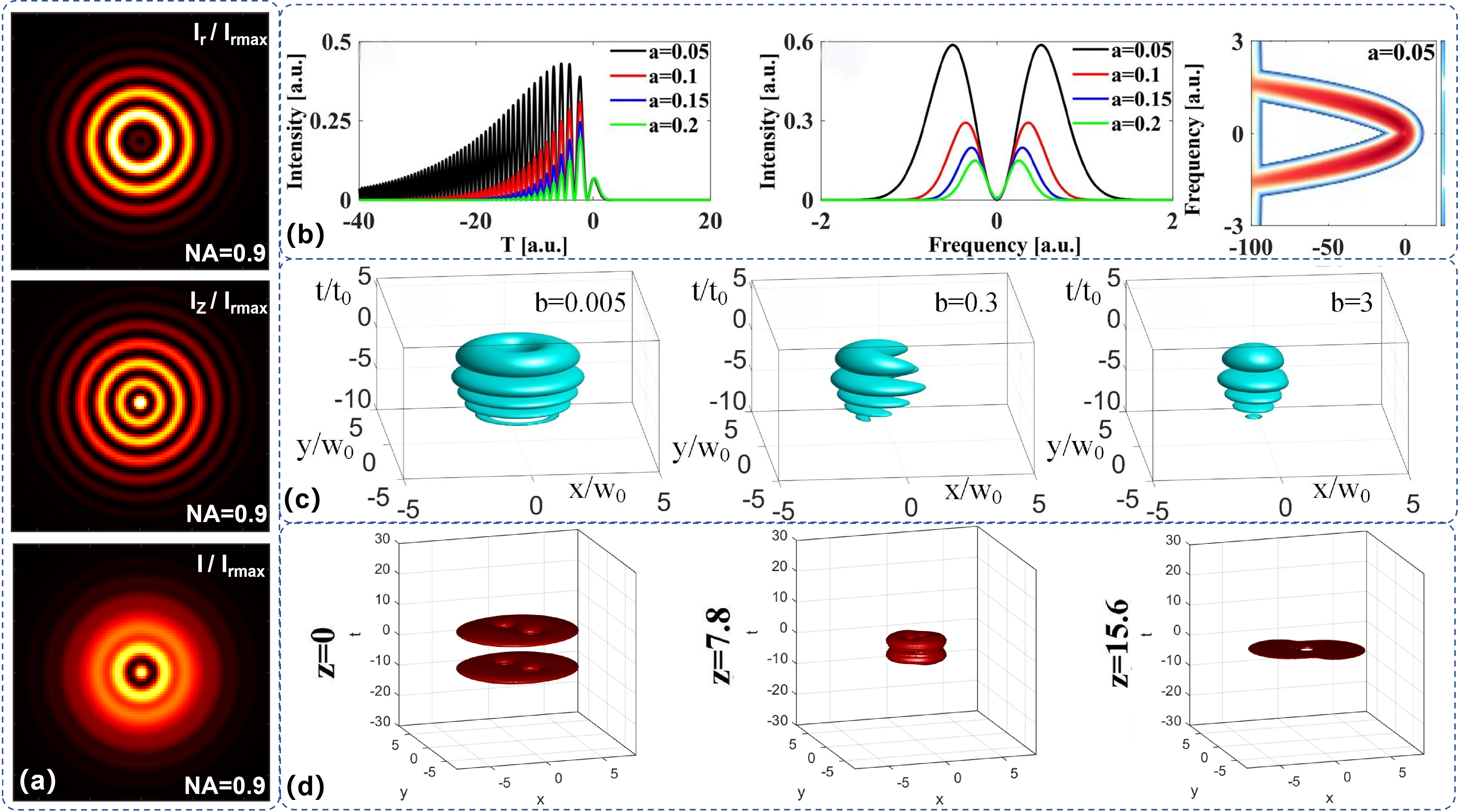
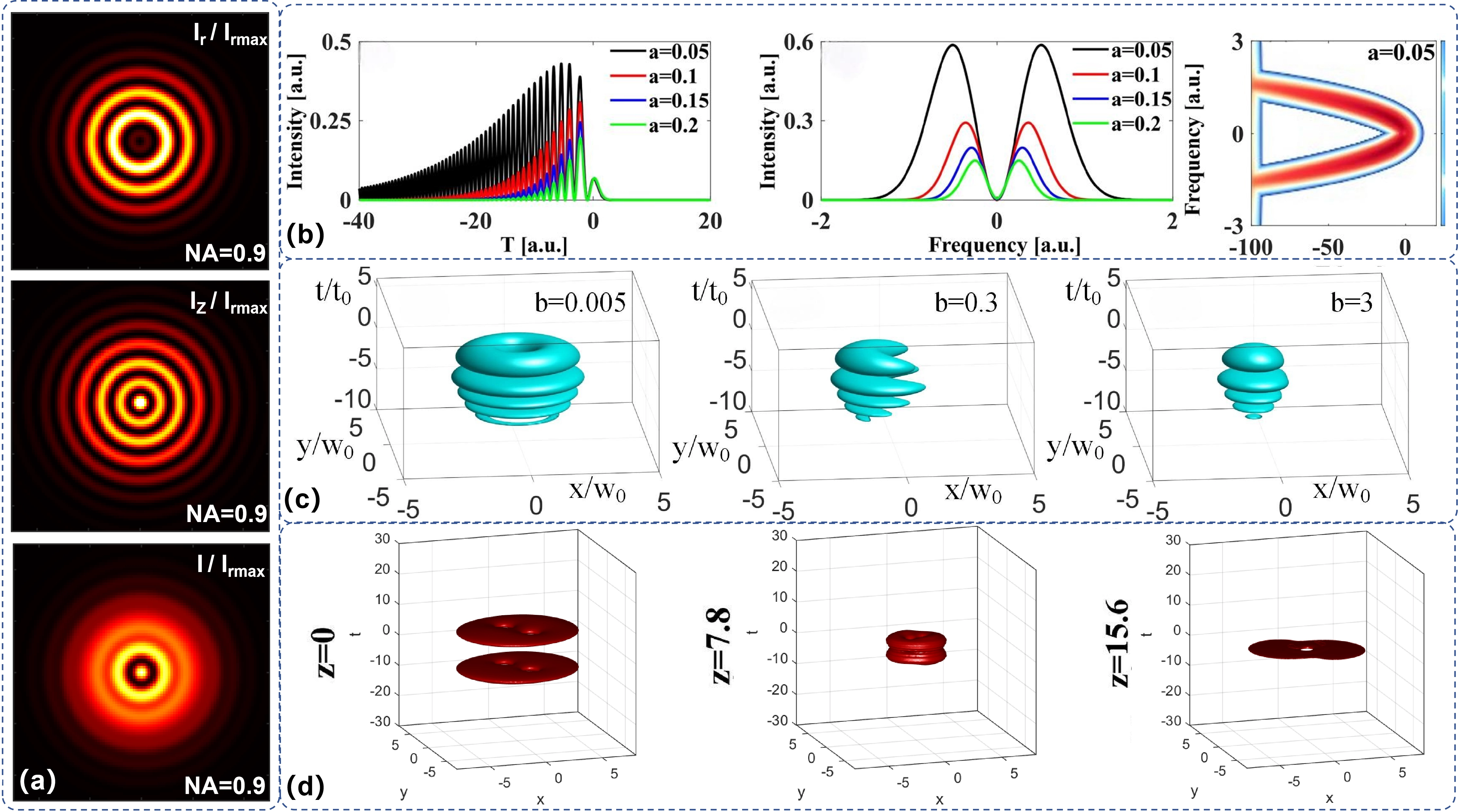
Figure 7. Additional variables and composite models. (a) Authors’ calculated radial, longitudinal, and total focal intensities at NA = 0.9 using the model and parameters[73]; (b) Temporal intensity, spectrum, and an XFROG distribution. Adapted from reference[112], CC BY 4.0; (c) Airyprime-Laguerre-Gaussian packet structures for b = 0.005, 0.3, and 3. Adapted from reference[22], CC BY 4.0; (d) Authors’ calculated fractional space-time packet evolution at z = 0, 7.8, and 15.6 with β = 1 and pt = 1.98 using the model and parameters[105]. All panels depict calculated fields, not vectorial or spatiotemporal measurements; source normalization and coordinate scales remain panel-specific.
6.2 Spatiotemporal Airyprime wave packets
Introducing time as an independent coordinate is conceptually different from changing a transverse modal basis. A temporal Airyprime pulse in a (1+1)-dimensional model contains one time coordinate and one propagation coordinate, with dispersion governing its evolution[112]. A (3+1)-dimensional wave packet additionally contains two transverse coordinates, but the Airyprime factor need not occupy those spatial coordinates: in representative constructions, a finite-energy Ai-prime temporal factor is multiplied by a separate complex-variable Gaussian or vortex-type transverse mode[99]. Consequently, the label “(3+1)D” records coordinate count, not necessarily nonseparable space-time dynamics. When the solution remains a product of independently evolving spatial and temporal factors, it supplies coordinated variables in the mathematical description without demonstrating strong intrinsic space-time coupling.
The propagation operator then determines how those coordinates evolve. Linear dispersive models predict temporal broadening, splitting, and relative control of spatial and temporal focal positions for Airyprime-containing packets[26]. Fractional diffraction or fractional Schrödinger formulations introduce spatial and temporal fractional indices that can alter focusing synchronization, trajectory, width, and energy distribution[105]. Harmonic-potential models add another operator-level control over packet evolution and have been accompanied by proposed generation and measurement arrangements[108]. These parameters enlarge the theoretical design space, but fractional order remains a model parameter in the audited evidence, and a proposed optical arrangement is not an experimental implementation. None of these studies reports direct spatiotemporal field measurement.
Nonlinear spatiotemporal models add self-action to an Airyprime or hybrid source. Strongly nonlocal and noninstantaneous formulations predict localized, rotating, breathing, or fragmented packets[22,99,100,113]. Related Ince-Gaussian and other composite models extend these calculated regimes[101,102]. The Airyprime factor sets part of the initial structure, whereas the nonlinear kernel, dispersion, and diffraction determine whether localization persists. Soliton terminology is appropriate only when a stated regime balances these effects and maintains morphology or stability. A localized numerical peak is not sufficient evidence of an optical bullet, and no nonlinear-material Airyprime spatiotemporal experiment was identified.
6.3 Higher-dimensional and composite degrees of freedom
Many nominally multidimensional Airyprime fields are modal or hybrid constructions. Laguerre-Gaussian, Hermite complex-variable Gaussian, Ince-Gaussian, sinh- or cosh-Gaussian, and polygonal or vortex factors modify the transverse basis, envelope, or symmetry[22,99,103,108]. Further composite models introduce additional indices that control morphology and calculated energy flow[100-102]. These indices are useful design variables, but they do not independently add polarization or time, and a new modal representation does not create a new physical dimension.
The same distinction applies to the governing equation. Fractional indices and variable diffraction modify the propagation operator[26,105,113]. Parabolic or harmonic potentials and delayed nonlinear kernels add other operator-level controls[103,106,108]. These parameters can change trajectories, periodicity, focal synchronization, morphology, and localization, but they are not additional coordinates. Genuine multidimensional dynamics require an explicit account of which variables are present and how they are coupled.
Airyprime extensions therefore form a layered description space. Polarization, temporal evolution, and nonparaxial longitudinal fields introduce physical variables absent from scalar stationary models, whereas modal hybridization and operator engineering provide mathematical controls. Current Airyprime evidence in these directions remains analytical or numerical. Scalar field measurements and vortex-parameter detection do not substitute for vectorial polarimetry or direct spatiotemporal measurement[23,24,125,126]. Longitudinally polarized Airy focusing supplies a vectorial modeling precedent[127]. Spatiotemporal Airy studies provide independent pulse and wave-packet precedents[128-130]. Radially polarized circular Airy focusing supplies another vectorial comparison[131]. Polarized and polarization-singularity Airy studies provide further field-design comparators[132,133]. Airy-Laguerre-Gaussian bullets, space-time packets, and nonparaxial Bessel-like waves extend the modal and propagation context[134-136]. Further tightly focused and vectorial studies define useful measurement targets[137-140]. These precedents do not raise the maturity of an Airyprime claim.
7. From Optical Forces to Demonstrated Applications
7.1 Reproducible maturity criteria
The maturity grade is assigned to a specific claim or function, not automatically to every result in a paper. A study receives the highest level supported by direct evidence for that claim, while lower-level components remain separately identified. Table 6 defines the minimum evidence required at each level and the observations that are insufficient for promotion.
Table 6. Operational criteria for L1-L5 evidence maturity. A level applies to a specific claim and requires the source definition and direct evidence specified in that row. Optical-field generation does not establish particle manipulation, and a functional laboratory demonstration does not establish a practical system.
| Level | Required evidence | Representative claim | Insufficient evidence |
| L1 Theory | Traceable field/model and explicit assumptions | Analytical source, propagation or functional hypothesis | Name, schematic or untestable application claim alone |
| L2 Numerical | Quantitative computation; parameters and observable stated | Calculated forces, BER, vector/space-time fields or learned descriptors[21,23,96] | Computed equilibrium or BER is not capture or a working link |
| L3 Optical field | Physical generation and measurement of the claimed field response | Measured intensity/propagation/recovery[19,33,34]; bottle/dual-focus structure[61,62] | Field image is not task response; simulation is not polarimetry |
| L4 Laboratory function | Direct task response linked to the Airyprime field | Capture/motion/mechanics[23,27,64,141]; vortex inference[24] | Calculated force or field geometry alone |
| L5 Practical system | Reproducible end-to-end operation; calibration, uncertainty, baseline, stability and realistic variability | No qualifying study found by the cutoff | Laboratory function, simulated metrics or transmitter alone |
BER: bit error rate.
Applying these rules resolves mixed-evidence papers without averaging their components. For example, the simulation-trained bottle descriptor in Ref.[23] is L2, the measured bottle field is L3, and the observed particle confinement is L4. Numerical communication metrics in Refs.[21,96] remain L2; direct optical-field measurements are L3; observed capture or parameter inference is L4; and calibrated stiffness or torque provides stronger quantitative support within L4. No result is promoted to L5 without end-to-end operation under the criteria in Table 6.
7.2 Optical forces and manipulation: From force models to trapping capability
For an Airyprime-derived field, the application boundary lies between predicting a particle response and observing that response. Calculations have evaluated forces, potentials, equilibrium points, and trajectories for several circular, vortex-loaded, and nonparaxial fields[70,73,101,111]. Hybrid and multidimensional packets extend the calculated design space[22,99,103]. Prescribed harmonic and parabolic potentials add separate operator-level controls[108,109]. Other studies examine specialized force geometries and particle assumptions[142,143]. These calculations test whether a specified field-particle system could support confinement or motion, but a force zero or favorable force balance does not demonstrate capture. Maturity is therefore assigned to the tested function rather than to the complexity of the field model.
The predicted response depends on the full engineered field, particle regime, refractive-index contrast, surrounding medium, incident power, and force model. Most calculations use Rayleigh or dipole approximations and idealized particles[70,73,109,111]. Selected reports also adopt particle dimensions or material assumptions that require careful physical interpretation[101,142,143]. Force magnitudes from different source geometries therefore cannot be compared without matched optical and particle conditions, and model-dependent trends should not be presented as experimentally realistic trapping performance.
An intermediate level of evidence is provided by measured optical structures combined with calculated particle responses. Hybrid focal fields, vortex-carrying derivative beams, chirped bottle fields, and lens-mapped dual foci have been generated or characterized experimentally[25,61,62,71]. Under the reported laboratory conditions, these results establish that selected candidate confinement geometries can be produced, while accompanying force, potential, or equilibrium calculations define testable functions. Nevertheless, a measured dark volume, multifocus distribution, or intensity maximum should be treated as an enabling optical structure rather than evidence of particle confinement. Figure 8 separates these field-level and functional claims. The authors’ dual-focus illustration represents a geometry measured in the cited study; it must not itself be interpreted as experimental data. Representative functions and their application maturity are compared in Table 7.
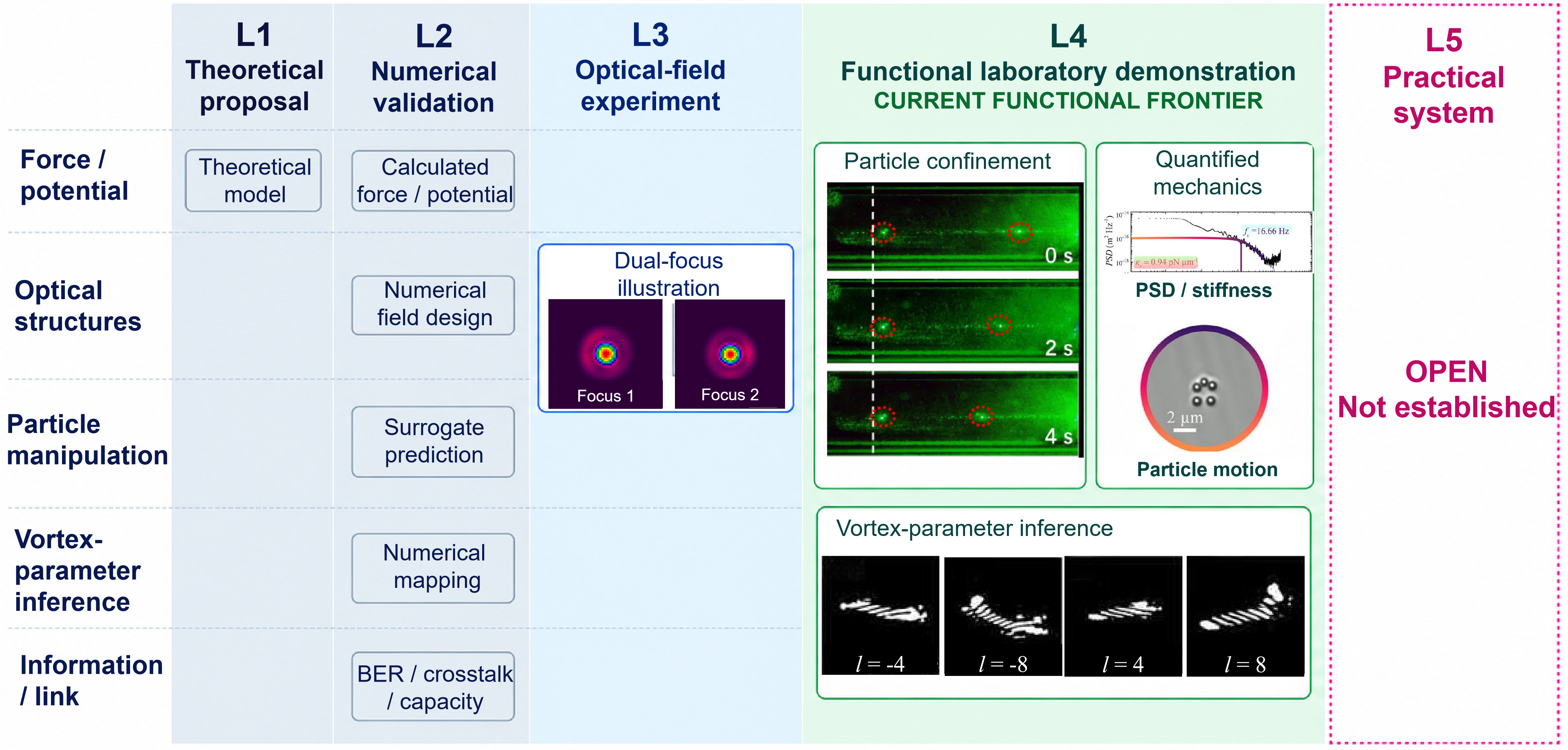
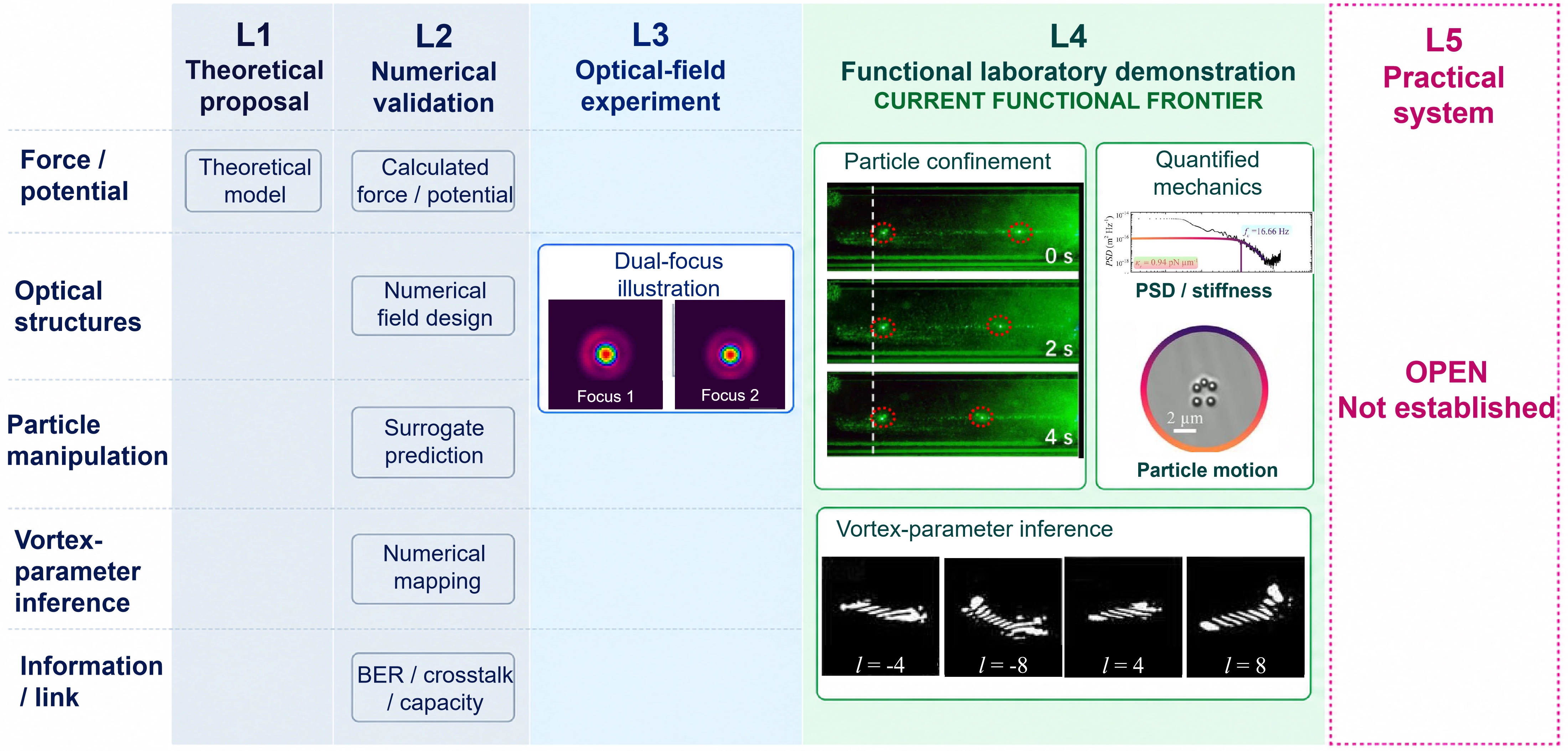
Figure 8. Claim-level L1-L5 maturity map with a comparative example of optical-bottle manipulation. L1-L2 entries are schematic summaries. The authors’ dual-focus illustration in the L3 column represents the geometry of the optical-field measurements reported[62]; the illustration itself is not measured data and does not independently qualify as L3 evidence. The experimental particle-manipulation photographs at 0, 2, and 4 s. Reproduced from reference[144]. CC BY 4.0. These photographs are a comparative example of dynamic holographic optical-bottle manipulation, not the authors’ original experimental data or evidence for an Airyprime-specific confinement claim. The PSD/stiffness and particle-motion images. Adapted from reference[141]. CC BY-NC-ND 4.0. Vortex-parameter-inference patterns. Adapted from reference[24]. CC BY-NC-ND 4.0. Observed confinement, measured mechanical response, and parameter inference support L4 claims when demonstrated for the specified field; calculated forces and communication metrics remain L2. No Airyprime study in the reviewed evidence set meets the L5 criteria in Table 6. BER: bit error rate; PSD: power spectral density.
Table 7. From predicted forces to measured applications. The table separates calculated response, measured optical structure, directly observed function, and system validation. Photophoretic and gradient-force mechanisms are not pooled, and numerical communication metrics are not link demonstrations.
| Function | Architecture | Demonstrated evidence | Limitation |
| Force/potential | Focused, vectorial or structured field | Calculated force, potential and equilibria | Not observed capture |
| Bottle/multifocus field | Bottle-forming or lens-mapped field | Generated/measured structure | Field geometry is not manipulation |
| Neural descriptor | Chain-bottle field | Simulation-trained predictor of field descriptors | Not inverse design or autonomous control |
| Particle confinement | Chain-bottle field | Observed laboratory confinement | Separate from neural prediction; not universal trapping |
| Photophoretic capture | Chirped elliptical vortex field in air | Capture of absorbing particles | Thermal mechanism; not aqueous gradient trapping |
| Programmable manipulation | Geometry-programmed trapping sites | Particle arrangement and motion | Selected conditions; not a general platform |
| Annular mechanics | Annular vortex bottle | Motion and selected mechanical observables | Not all-axis calibration or universal superiority |
| Calibrated array trapping | Coherent array/bottle | Multi-site trapping and selected calibrated response | Baseline, geometry and efficiency dependent |
| Vortex inference | Elliptical Airyprime phase mask | Parameter retrieval from diffraction patterns | Not full OAM spectrum or practical receiver |
| Channel prediction | Cartesian or vortex channel model | Calculated BER, crosstalk or capacity | No demonstrated Airyprime link/L5 system |
BER: bit error rate; OAM: orbital angular momentum.
7.3 Experimental particle manipulation and functional optical structures
Current evidence most clearly supports the transition from field design to observed function in particle manipulation. A useful example is the neural-network-assisted design of Airyprime chain optical bottle beams[23]. The network predicts bottle number and maximum size from a simulation-derived data set, which constitutes numerical validation of a structural model. In a separate functional experiment under the tested conditions, particle confinement was directly observed, raising that claim to a laboratory demonstration[23]. The particle-manipulation photographs in Figure 8 instead come from a separate dynamic holographic optical-bottle experiment[144]. They illustrate a functional comparison and are not images from the Airyprime chain-bottle study or evidence validating its predictor. The two components therefore occupy different maturity levels even though they appear in the same study: model accuracy validates the bottle description, whereas the recorded particle response validates confinement. The result does not by itself establish general prediction outside the training distribution or universal trapping performance, because particle identity, laser power, trap stiffness, and associated uncertainties were not reported.
Programmable particle response has also been demonstrated under tested conditions with selected geometry-engineered circular Airyprime-vortex fields. In the reported experiment, 3 μm polystyrene beads in water were captured and rearranged into hexagonal, triangular, and caterpillar-like configurations[64]. The observed configurations indicate that source geometry and singularity placement can be translated into multiple trapping sites and controlled particle organization within this system. The application-relevant output is thus the particle configuration, not merely the structured focal intensity. This provides more direct functional evidence than a force map or measured focal pattern because particle motion is observed. Its scope nevertheless remains that of a specific proof-of-principle system: calibrated stiffness and a matched efficiency benchmark were not provided, and calculated orbital-angular-momentum characteristics should not be treated as measured modal content.
Among the more mature functional evidence, mechanical observables supplement particle images. Under their respective tested conditions, dual circular Airyprime-vortex bottle fields have produced annular orbital motion for 1 μm polystyrene particles, with the orbit radius, angular speed, radial stiffness, and optical torque evaluated experimentally[141]. Dual-ring Airyprime-Gaussian arrays have likewise enabled three-, four-, and five-point trapping and bottle confinement of 1 μm polystyrene particles, with PSD analysis used to determine trap stiffness[27]. These measurements move beyond establishing capture toward quantifying mechanical response and allow the trapping function to be assessed independently of visual field morphology. They remain laboratory demonstrations rather than validated practical systems. Their reported numerical advantages are configuration- and baseline-specific, however, and should not be generalized to unmodulated Airyprime fields, other particle classes, or different optical resources without matched comparisons.
One distinct manipulation mechanism is represented by photophoretic capture of absorbing mesocarbon microbeads in air using a chirped elliptical Airyprime-vortex bottle field[125]. Under the reported conditions, camera observations support experimental particle capture, but photophoretic motion arises from light-induced thermal effects rather than the gradient-force mechanism commonly used for dielectric particles in water. It should therefore not be pooled quantitatively with conventional optical-tweezer demonstrations. The different particle material, surrounding medium, and response mechanism also prevent a direct performance ranking against the aqueous studies. The study was initially available as a preprint and subsequently published in Optics Communications, while retaining the same experimental-evidence classification. Taken together, the current manipulation literature demonstrates selected Airyprime-derived functions at laboratory scale, but does not yet establish a universal trapping platform or a practical-system-level technology.
7.4 Optical detection, information processing, and emerging functionalities
Outside particle manipulation, the most clearly demonstrated function in the audited evidence is fixed-plane detection of vortex parameters. An elliptical Airyprime phase mask was used with an SLM and CCD to map the magnitude and sign of a power-exponent-phase vortex topological charge onto fringe number and orientation, while the first-lobe length provided an estimate of the power exponent[24]. Under the tested parameter ranges, this experiment establishes diffraction-derived vortex-parameter inference. It does not constitute a complete OAM-spectrum measurement, nor does it show a general-purpose sensor or communication receiver; the demonstrated function is the retrieval of specified vortex parameters from a calibrated diffraction pattern.
Information and communication claims currently remain at lower maturity. Numerical propagation studies have evaluated turbulence-dependent scintillation and BER-related metrics for Cartesian Airyprime beams[21], and have calculated OAM crosstalk, BER, and average capacity for ring Airyprime-vortex channels[96]. These results evaluate candidate system behavior, but no data transmission was performed in the audited studies. Conditional Airy transformation of an Airyprime input has been verified as an optical-field operation[31]; its suggested information use remains conceptual because neither encoded data nor a link experiment was demonstrated. Related work on conventional circular Airy beams has demonstrated data-driven inversion of source parameters from compact focal measurements using simulation-trained regressors, experimental forward-model validation, and uncertainty-aware prediction. This provides a relevant methodological precedent, but does not constitute Airyprime-specific inverse-design evidence.
Application maturity remains uneven. Selected Airyprime-derived fields have enabled particle confinement, rearrangement, orbital motion, and mechanically quantified trapping[23,27,64,141]. Photophoretic capture supplies a mechanism-specific example[125]. Diffraction-based vortex-parameter detection provides a non-manipulation demonstration[24]. Most force landscapes, bottle geometries, sensing concepts, and communication metrics remain theoretical, numerical, or optical-field results. Conventional Airy beams provide functional benchmarks in microscopy, imaging, nonlinear generation, and particle clearing[145-148]. Other work addresses optical pulling and focusing[149-151]. Spectral switching in imaging and long-range needle-like focusing supply separate functional comparators[152,153]. Particle sorting, integrated tweezers, and topological manipulation provide additional functional and platform context[154-156]. Metasurface atom traps and an underwater Airy-beam transmitter illustrate distinct system-level developments[157,158]. Spatiotemporal optical links provide a separate information-related precedent[159]. Classical Airy trapping, force calculations, and particle guiding define further laboratory and modeling baselines[160-163]. Loss-resistant transport and focused trapping complete this comparison set[164-166]. These studies are not counted as Airyprime maturity evidence. Airy-beam tomographic microscopy provides an independent imaging benchmark[167]. Switchable second-harmonic Airy and Airy-vortex generation supplies a frequency-conversion precedent[168].
8. Outlook and Future Perspectives
8.1 Bridging the gap between optical structures and functional systems
Current Airyprime research encompasses finite-energy source construction, propagation and autofocusing, field engineering, complex-environment models, expanded degrees of freedom, and selected functional experiments. The maturity of this evidence, however, remains uneven. Optical generation and propagation have been measured for many scalar fields. Particle confinement, rearrangement, orbital motion, and calibrated trapping provide selected L4 demonstrations[23,27,64,141]. Vortex-parameter inference supplies a separate laboratory detection function[24]. No Airyprime-specific L5 practical system has yet been established. The central translational challenge is therefore not simply to create a more elaborate intensity distribution, but to connect a traceable source definition to calibrated generation, stable operation, and reproducible task-level performance under realistic conditions.
Many current optical experiments rely on SLM encoding, spatial filtering, Fourier or relay systems, and camera-based field verification. These arrangements provide valuable reconfigurability, but their performance depends on alignment, phase fidelity, aperture, pixelation, filtering loss, detector calibration, and temporal stability. A generated field is not by itself a practical device. Progress toward reproducible systems requires full generation-transfer characterization, including the fidelity of both amplitude and phase, incident and transmitted power, diffraction efficiency, field reconstruction, uncertainty, and repeatability across alignments or platforms. Compact or integrated generation may become an important objective, but it remains a future direction rather than an established Airyprime capability. Any such implementation should be assessed by how faithfully and efficiently it reproduces the required field, not merely by a reduction in component count.
Translation also requires consistent performance benchmarking. Source-normalized peak contrast, including the autofocusing factor K, is informative but does not measure energy efficiency or application quality on its own. Comparisons intended to guide system design should declare input-power normalization, transmitted power, physical aperture, numerical aperture, wavelength, focal distance, transverse and axial width definitions, focusing efficiency, sidelobes, stability, and uncertainty. The task-level observable must also be explicit: a narrower focus, longer depth of focus, higher K, lower fluctuation, greater trap stiffness, or improved detection accuracy addresses a different objective. A better value of one optical metric does not automatically imply a better application. Future optimization should therefore use matched resources and multi-objective criteria, preserving trade-offs rather than combining maxima obtained under different settings.
8.2 Intelligent design and inverse engineering of Airyprime fields
Current Airyprime-specific evidence supports a limited role for machine learning. A simulation-trained neural network has predicted the number and maximum size of Airyprime chain optical bottles, while particle confinement was validated separately[23]. The model is a task-specific L2 forward predictor; the L4 confinement experiment does not upgrade it to an inverse-design or autonomous-control system. This evidence also does not establish transfer across beam families, hardware, wavelengths, particles, or applications. AI-assisted Airyprime field design should be evaluated against direct searches and physics-based solvers, with transparent data coverage, error reporting, and tests on measured fields.
Physics-guided inverse design is a well-defined future direction because the field has a forward structure that maps source parameters and composable operations to focal distance, K, width, depth of focus, morphology, topology, and application observables. A credible inverse formulation would begin with a target function and resource budget, then determine a realizable source and operation under propagation and hardware constraints. It should include aperture, modulation bandwidth, phase quantization, throughput, and SLM or manufacturing limits, with multi-objective losses connected to measured outcomes. Airyprime-specific physics-informed inverse design with functional validation is not established and should be treated as a research program rather than a present platform.
For practical control, surrogate speed alone is insufficient. Experimental models must quantify uncertainty and recognize domain shifts caused by aberration, drift, calibration error, environmental perturbation, and sample variability. Experiment-in-the-loop control could update a constrained design using in situ field or task measurements, but autonomous Airyprime optimization has not been demonstrated. Progress requires uncertainty estimates validated against independent simulations and experiments, explicit failure cases, and stable feedback based on an application metric rather than visual agreement with a simulated intensity pattern. These requirements distinguish AI-assisted optimization from an autonomous optical system.
8.3 Toward experimentally validated multifunctional Airyprime platforms
The modularity of Airyprime-field engineering supports multifunctionality as a future objective. Amplitude, phase, spectral, topological, coordinate, hybrid, and coherent-array operations can be composed, while current experiments provide separate evidence for particle manipulation and vortex-parameter detection. Yet a multifunctional field design is not equivalent to a multifunctional device. A future platform combining manipulation, sensing, information processing, or adaptive control would need each function to be measured independently, with no transfer of maturity from one task to another. It would also require explicit analysis of shared resources and conflicts, including optical power, efficiency, bandwidth, switching speed, calibration, stability, and the effect of reconfiguration on every task-level observable.
Vectorial, spatiotemporal, nonlinear, fractional, and engineered-medium Airyprime fields broaden the candidate design space, but at present they remain primarily analytical and numerical extensions. Vector-field polarimetry, direct spatiotemporal Airyprime pulse measurement, nonlinear-material validation, and physical implementation of fractional or engineered operators remain unestablished in the audited evidence. Future efforts may prioritize experimentally plausible regimes in which the added degree of freedom can be generated and completely characterized. Any claimed functional advantage should then be tested against a scalar or conventional alternative under matched power, aperture, numerical aperture, and environmental conditions. Mathematical dimensionality or operator complexity alone is not evidence of system value.
8.4 Near-term priorities and long-term goals
The near-term priority is reproducible optical generation and matched reporting. Section 3 and Section 5 show that aperture, input power, transmitted power, width definition, recovery metric, calibration, and uncertainty are often incomplete or inconsistent. The main challenge is therefore measurement discipline: experiments should report the resources and definitions needed to reproduce the field and compare it with a conventional Airy, Gaussian, Bessel, Pearcey, or other relevant baseline.
A medium-term priority is to convert the analytical and numerical evidence in Section 5 and Section 6 into complete field measurements. Vector Airy studies provide precedents for polarization-resolved field construction and modeling[169-171]. Symmetric vector beams and vector-beam optical chains supply further implementation targets[172,173]. Spatiotemporal Airy measurements provide complementary precedents for resolving coupled space-time structure[174-176]. Turbulence studies illustrate how propagation statistics and channel effects can be measured under controlled perturbations[177-180]. For Airyprime fields, the central challenge is simultaneous control and measurement of the added degree of freedom without transferring maturity from a scalar intensity image or numerical model. High-altitude adaptive Airy generation and laboratory circular-Airy drift measurements offer additional implementation and calibration precedents[181,182].
The long-term goal is an Airyprime-specific end-to-end system whose task performance requires the Airyprime source. Communication experiments with conventional OAM and self-healing beams show the level of transmitter, channel, receiver, crosstalk, and error-rate validation expected of a practical link[183-186]. Comparable validation in manipulation or sensing would require compact generation, calibrated efficiency, stability, uncertainty, matched baselines, and reproducible operation over relevant samples or environments. These requirements connect the open evidence gaps in Section 5, Section 6 and Section 7 to the translation gates summarized in Figure 9.
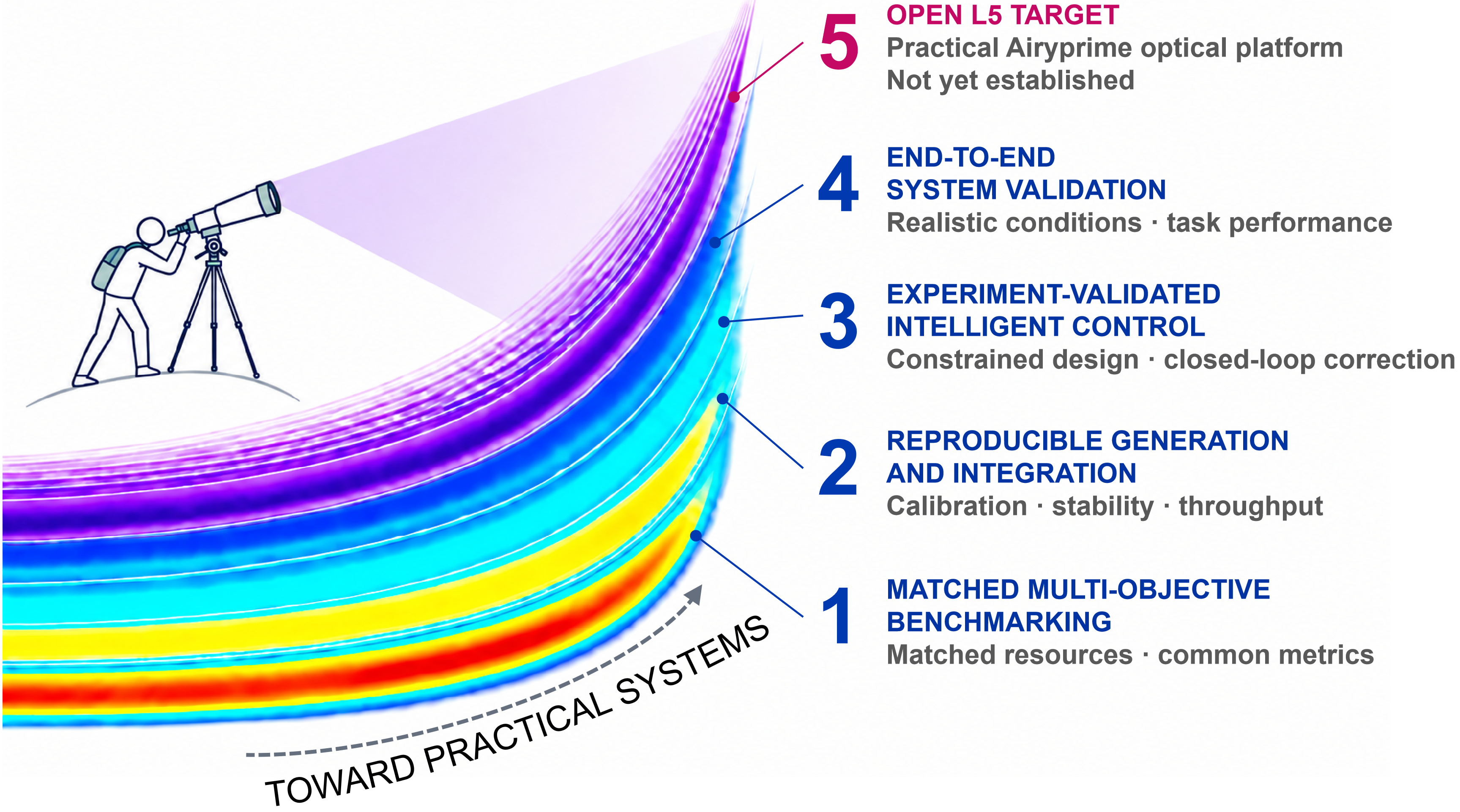
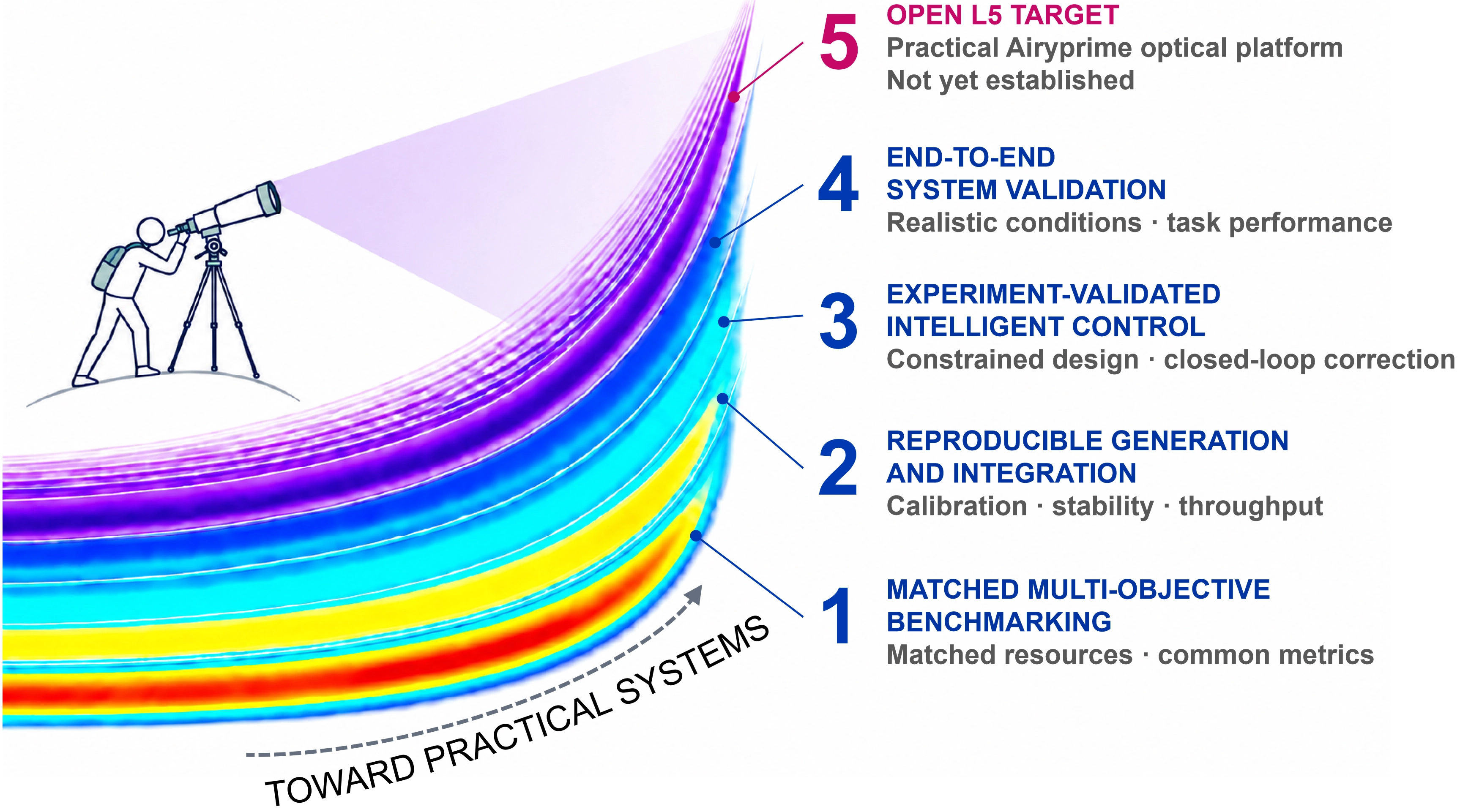
Figure 9. Conceptual Airyprime-shaped roadmap toward a practical optical platform. Four translation gates connect the current evidence frontier to the open L5 target: matched benchmarking, reproducible generation and integration, experimentally validated intelligent control, and end-to-end system validation. The numbered gates denote priorities, not L1-L5 grades; the fading higher-order lobes symbolize future possibilities rather than measured performance.
A true L5 Airyprime demonstration would require an end-to-end function in a realistic environment, a compact and stable implementation, calibrated task performance, uncertainty analysis, a matched baseline, and reproducible operation. Electron Airyprime calculations and acoustic or fluidic Airy demonstrations suggest possible cross-domain directions[187-189]. Atomic acceleration and tomographic microscopy provide separate application precedents[190,191]. Airy-beam dynamics, pulse control, and laser generation provide additional implementation precedents[192-195]. Bessel-like trajectories, full-wave accelerating solutions, and partial coherence extend the available design concepts[196-199]. None of these studies fills the open Airyprime L5 category.
9. Conclusion
This Review establishes Airyprime beams as a finite-energy derivative-field framework rather than a collection of isolated beam variants. Its development is most coherently understood by following the connection from source construction to propagation mechanism, deliberate control operation, propagation environment, and measured functionality. This perspective separates properties intrinsic to an Airyprime source from those introduced by chirp, topology, coordinate transformation, hybridization, or coherent superposition, while also distinguishing mathematical possibility from experimental evidence. It thereby provides a common basis for interpreting a literature that otherwise appears fragmented across a growing number of field names and parameter-dependent performance claims. The resulting picture is not one of a completed or uniformly mature field, but of a structured research framework whose physical principles, engineering operations, and evidentiary boundaries can now be stated more precisely.
At the conceptual level, the adopted framework contains two related but mathematically non-equivalent source constructions: a Cartesian finite-energy Airyprime field generated through an Airy transformation and a generalized circular Airy derivative family whose first-order member is the circular Airyprime beam. Their shared Airy-derivative structure does not remove the differences in coordinate geometry, source measure, parameter definition, and propagation description. Correspondingly, Cartesian coherent intensity redistribution and circular abrupt autofocusing should not be reduced to a single universal interference mechanism. The circular literature further shows that self-healing depends on the chosen observable and that peak-based autofocusing contrast cannot replace focal width, depth of focus, efficiency, sidelobes, transmitted power, or stability in a fair assessment. Across both branches, amplitude and phase shaping, spectral filtering, asymmetric control, vortex loading, coordinate transformations, hybrid envelopes, and coherent arrays form a modular engineering toolbox. These operations can redistribute energy and reconfigure morphology or focal structure, but greater field complexity does not automatically produce greater efficiency, robustness, or functional value.
The evidence also shows that Airyprime research has progressed beyond analytical construction and optical-field generation toward selected function-level laboratory demonstrations. Airyprime-derived fields have supported particle confinement, programmable rearrangement, orbital manipulation, and mechanically quantified trapping under specific experimental conditions, while diffraction-pattern measurements have enabled inference of selected vortex parameters. These results provide the clearest present basis for discussing Airyprime-based applications. Their scope nevertheless remains bounded by the tested fields, particles, optical arrangements, and observables. Many other directions, including force and potential calculations, bottle and lattice structures without a measured end use, communication-related simulations, and most nonlinear, fractional, vectorial, and spatiotemporal extensions, remain theoretical, numerical, or optical-structure demonstrations. Neither simulated system metrics nor a generated field establishes a communication link, an autonomous design system, or a practical optical platform.
The evidence therefore identifies a clear boundary between a mature field-design framework and an immature system technology. Airyprime beams connect structured-source design with selected laboratory functions, but practical system realization remains unestablished. Claims of progress should be tied to matched-resource benchmarking and task-level validation rather than inferred from a single optical metric or a visually distinctive field pattern.
Acknowledgements
DeepSeek-V4.1-Flash-1017 was used for language polishing during manuscript preparation. The authors reviewed and revised the AI-assisted edits, approved the final manuscript, and take full responsibility for its content.
Authors contribution
Liu Z: Writing-original draft, methodology, investigation, formal analysis, data curation, conceptualization.
Gao H: Investigation, formal analysis, data curation, conceptualization.
Zheng Y: Investigation, formal analysis.
Wang F: Supervision, resources, methodology, funding acquisition.
Zhou G: Writing-review & editing, supervision, resources, funding acquisition, data curation.
Conflicts of interest
The authors declare no conflicts of interest.
Ethical approval
Not applicable.
Consent to participate
Not applicable.
Consent for publication
Not applicable.
Availability of data and materials
No new experimental data were collected for this Review. The authors’ numerical illustrations use the models and parameters of the cited studies. The other evidence discussed in this Review is available in the cited publications.
Funding
This research was supported by National Natural Science Foundation of China (Grant Nos. 12374281 and 12274311).
Copyright
© The Author(s) 2026.
References
-
1. Berry MV, Balazs NL. Nonspreading wave packets. Am J Phys. 1979;47(3):264-267.[DOI]
-
5. Panagiotopoulos P, Papazoglou DG, Couairon A, Tzortzakis S. Sharply autofocused ring-Airy beams transforming into non-linear intense light bullets. Nat Commun. 2013;4:2622.[DOI]
-
6. Voloch-Bloch N, Lereah Y, Lilach Y, Gover A, Arie A. Generation of electron Airy beams. Nature. 2013;494(7437):331-335.[DOI]
-
11. Efremidis NK, Chen Z, Segev M, Christodoulides DN. Airy beams and accelerating waves: An overview of recent advances. Optica. 2019;6(5):686-701.[DOI]
-
12. Rogel-Salazar J, Jiménez-Romero HA, Chávez-Cerda S. Full characterization of Airy beams under physical principles. Phys Rev A. 2014;89(2):023807.[DOI]
-
13. Dai H, Mohamed ZAY, Xiao A, Xue Y, Guo Z, Zhang Y, et al. Magnetically tunable Airy-like beam of magnetostatic surface spin waves. Chin Opt Lett. 2021;19(1):013501.[DOI]
-
15. Shi X, Shentcis M, Kurman Y, Wong LJ, de Abajo FJG, Kaminer I. Free-electron-driven X-ray caustics from strained van der Waals materials. Optica. 2023;10:292-301.[DOI]
-
17. Li T, Zhang X, Huang K, Lu X. Experimental generation of partially coherent circular Airy beams. Opt Laser Technol. 2021;137:106814.[DOI]
-
18. Efremidis NK, Paltoglou V, von Klitzing W. Accelerating and abruptly autofocusing matter waves. Phys Rev A. 2013;87(4):043637.[DOI]
-
24. Yu X, Chen K, Ma J, Nie S, Yuan C. In-situ detection of power-exponent-phase vortex beams using an elliptical Airyprime phase mask. Laser Part Beams. 2026;44(1):10005.[DOI]
-
26. Chen C, Huang Z, Wang X, Shao Y, Luan K, Zhang X, et al. Tunable propagation characteristics of hybird Airyprime-Gaussian-vortex spatiotemporal wave packets in dispersive media. Opt Express. 2025;33(21):44062-44070.[DOI]
-
27. Chen J, Gao H, Zheng Y, Hu D, Zhu X, Wang F, et al. Enhancing optical trapping with topological-charge-tailored Airyprime-Gaussian beam arrays. Photon Res. 2026;14(4):1182-1196.[DOI]
-
28. Chen J, He J, Wang F, Zhou Y, Xu Y, Chen R, et al. Propagation of generalized Airy derivative beams in free space. Opt Laser Technol. 2025;180:111600.[DOI]
-
31. Chen J, Gao H, He J, Wang F, Zhou Y, Xu Y, et al. Airy transformation of Airyprime beam. Acta Phys Sin. 2025;74(12):124204.[DOI]
-
34. Kumari A, Dev V, Pal V. Autofocusing and self-healing of partially blocked circular Airy derivative beams. Opt Laser Technol. 2024;168:109837.[DOI]
-
36. Kumari A, Dev V, Pal V. Abrupt autofocusing of circular Airy derivative beams in complex media. Opt Laser Technol. 2025;183:112319.[DOI]
-
37. He J, Dan W, Zang X, Zhou Y, Wang F, Cai Y, et al. How to select the dimensionless radius to realize the strongest abruptly autofocusing ability of circular Airyprime beams. Opt Laser Technol. 2024;168:109932.[DOI]
-
38. Kumari A, Pal V. Abrupt autofocusing and scintillation dynamics of truncated circular Airy derivative beams in strong turbulence. Opt Commun. 2026;607:132923.[DOI]
-
41. Efremidis NK, Christodoulides DN. Abruptly autofocusing waves. Opt Lett. 2010;35(23):4045-4047.[DOI]
-
43. Manousidaki M, Papazoglou DG, Farsari M, Tzortzakis S. Abruptly autofocusing beams enable advanced multiscale photo-polymerization. Optica. 2016;3(5):525-530.[DOI]
-
45. Jiang Y, Yu W, Zeng K. Arbitrary shaped abruptly autofocusing beams. Opt Laser Technol. 2023;159:108963.[DOI]
-
48. Li T, Zi F, Huang K, Lu X. Multifocus autofocusing Airy beam. J Opt Soc Am A. 2017;34(9):1530-1534.[DOI]
-
49. Xu C. Circular symmetric Airy beam. Opt Commun. 2020;475:126190.[DOI]
-
51. Wu Y, Xu C, Lin Z, Qiu H, Fu X, Chen K, et al. Abruptly autofocusing polycyclic tornado ring Airy beam. New J Phys. 2020;22(9):093045.[DOI]
-
52. Davis JA, Cottrell DM, Sand D. Abruptly autofocusing vortex beams. Opt Express. 2012;20(12):13302-13310.[DOI]
-
54. Liang Y, Tan L, Liu N, Chen K, Liang H, Wu H, et al. Tunable autofocusing and enhanced trapping forces with circular Pearcey Airy beams. Phys Rev Appl. 2023;19:014016.[DOI]
-
56. Vo S, Fuerschbach K, Thompson KP, Alonso MA, Rolland JP. Airy beams: A geometric optics perspective. J Opt Soc Am A. 2010;27(12):2574-2582.[DOI]
-
62. He J, Chen J, Wang F, Zhou Y, Liu Z, Cai Y, et al. Tunability of double foci of a circular Airyprime beam achieved by a movable thin convex lens. Opt Laser Technol. 2025;183:112352.[DOI]
-
65. Zang X, Wang F, Dan W, Zhou Y, Zhou G. Propagation dynamics of abruptly autofocusing circular Airyprime beam with an optical vortex. Opt Laser Technol. 2022;155:108398.[DOI]
-
66. Dan WS, He J, Zang X, Wang F, Zhou YM, Chu XX, et al. Abrupt autofocusing performance of a circular Airyprime beam with vortex pairs. Results Phys. 2023;47:106377.[DOI]
-
67. Gao H, Chen J, Liu Z, Wang F, Cai Y, Zhou G. Dynamically tunable optical lattices based on interference of two linearly chirped elliptical Airyprime vortex beams. Chaos Solitons Fractals. 2025;199:116872.[DOI]
-
69. Gao H, Chen J, Zheng Y, Liu Z, Wang F, Cai Y, et al. Evolution of multilayer optical lattices based on linearly chirped circular Airyprime vortex beams. Chaos Solitons Fractals. 2026;202:117451.[DOI]
-
71. Yang S, Yu P, Wu B, Ge X, Chen C, Man Z, et al. Controllable autofocusing circular Pearcey Airyprime beam. J Phys D: Appl Phys. 2025;58(8):085107.[DOI]
-
73. Luan K, Li S, Zhang X, Zhang X, Chu Y, Man Z, et al. Tight-focusing properties of the radially polarized Airyprime Gaussian vortex beam. Opt Commun. 2025;592:132233.[DOI]
-
74. Zhou Y, Zang X, Dan W, Wang F, Chen R, Zhou G. Design and realization of an autofocusing Airyprime beams array. Opt Laser Technol. 2023;162:109303.[DOI]
-
76. Chen J, He J, Gao H, Zhou Y, Wang F, Cai Y, et al. Maximizing uniformity of light intensity in an Airyprime-Gaussian beam elliptical array via optimization of core parameters. Opt Laser Technol. 2025;186:112619.[DOI]
-
77. Liu Y, Xu G, Zhuang C, Wu B, Liu Z, He Y, et al. Controllable optical bottles from chirped elliptical Airy Gaussian vortex beams. Chaos Solitons Fractals. 2025;193:116108.[DOI]
-
78. Li X, Zhang Y, Liu M, Li J, Sun J, Wu W, et al. Generation of variable light fields by radially polarized chirped circular Airy vortex beams. Opt Laser Technol. 2025;181:111724.[DOI]
-
79. Zhan K, Zhang Q, Wang K, Ma Y, Chen Q, Yao G. Propagation dynamics of vortex Airy beams with quadratic phase modulation. Opt Laser Technol. 2025;180:111598.[DOI]
-
80. Chen RP, Ooi CHR. Nonclassicality of vortex Airy beams in the Wigner representation. Phys Rev A. 2011;84(4):043846.[DOI]
-
83. Wu Y, Lin Z, Xu C, Fu X, Chen K, Qiu H, et al. Off-axis and multi optical bottles from the ring Airy Gaussian vortex beam with the astigmatic phase. Ann Der Phys. 2020;532(7):2000188.[DOI]
-
84. Zha Y, Huang K, Liu B, Sun M, Hu H, Li N, et al. Elliptical Airy beam. Appl Opt. 2018;57(23):6717-6720.[DOI]
-
85. Xie W, Zhang P, Wang H, Chu X. Propagation of a vortex elliptical Airy beam. Opt Commun. 2018;427:288-293.[DOI]
-
92. Hwang CY, Choi D, Kim KY, Lee B. Dual Airy beam. Opt Express. 2010;18(22):23504-23516.[DOI]
-
93. Liang Y, Tan C, Chen C. Marked improvement of auto-focusing vortex beam performance in atmospheric turbulence based on the fractional system. Chaos Solitons Fractals. 2026;207:118018.[DOI]
-
94. Ren W, Liu X, Xu C, Wang Z, Gao Y, Fan D, et al. Dynamics of generalized Airy-derivative beams in nonlocal nonlinear media. J Opt Soc Am B. 2026;43(6):1267-1273.[DOI]
-
97. Zhang X, Li C, Ge X, Chen C, Wang B, Man Z, et al. Guiding the circular Airyprime Gaussian beam propagation along predesigned trajectories in the Kerr medium. Opt Commun. 2025;594:132296.[DOI]
-
100. Wang R, Liu Z. Evolution of spatiotemporal Airyprime Hermite complex-variable-function Gaussian wave packets in a strongly nonlocal nonlinear medium. Opt Commun. 2025;591:132138.[DOI]
-
101. Xu G, Liu Y, Xu L, Pang Y, Wu S, Qi J, et al. Propagation properties and radiation forces of airyprime-sinh-Gaussian wave packets in strongly nonlocal nonlinear media. Phys Lett A. 2026;581:131547.[DOI]
-
102. Liu Z, Wang R. Spatiotemporal airyprime Ince-Gaussian wave packets in strongly nonlocal nonlinear media. Phys Scr. 2026;101(16):165506.[DOI]
-
103. Liang Y, Deng Y, Liu X, Tan C, Liu X, Xie W. Self-focusing multidimensional regulation Airyprime polygonal perfect vortex fractional wave packets in three-dimensional parabolic potential. Chaos Solitons Fractals. 2026;209:118526.[DOI]
-
104. Zhao S, Li J, Li T, Huang X, Bai Y, Fu X. Dynamics of Airyprime beams with higher-order spectral phase modulation in the fractional Schrödinger equation. Laser Phys. 2024;34(9):095001.[DOI]
-
105. Tan C, Liang Y, Zou M, Liu M, Zhang L. Independent and controllable space-time autofocused dual Airyprime Hermite complex-variable-function Gaussian fractional wave packets. Chaos Solitons Fractals. 2025;201:117327.[DOI]
-
106. Liang Y, Zou M, Liu M, Tan C. Space-time controllable Airyprime Hermite complex-variable-function Gaussian wave packets in the variable diffraction fractional system. J Nonlinear Optic Phys Mat. 2025.[DOI]
-
107. Chen D, Jiang D, Xiao Z. Study on the evolutionary characteristics of airyprime beams in Gaussian-type PT symmetric optical lattices. Photonics. 2025;12(6):566.[DOI]
-
108. Wang H, Li J, Yu S, Jia S, Li Y, Peng J. Spatiotemporal chirped airyprime complex-variable Gaussian wave packets in a harmonic potential. Opt Express. 2026;34(17):32751-32765.[DOI]
-
109. Zhang L, Yang S, Li S, Man Z, Ge X, Lei C, et al. Controllable circular Airyprime beam with the astigmatic phase in a parabolic potential. Chaos Solitons Fractals. 2024;181:114506.[DOI]
-
110. Wang W, Mi Z, Zhang L, Wang B, Han K, Lei C, et al. The abruptly autofocusing characteristics of the circular Airyprime beam in a chiral medium. Opt Commun. 2023;549:129879.[DOI]
-
111. Yu J, Wang Y, Bai Z, Wu L, Fu C, Liu S, et al. Nonparaxial propagation and the radiation forces of the chirped circular Airy derivative beams. Opt Express. 2023;31(7):11053-11066.[DOI]
-
112. Chen D, Jiang D, Xiao Z. Propagation properties of Airyprime pulses in relaxing nonlinear media. Open Phys. 2025;23:20250210.[DOI]
-
113. Han X, Li S, Ge X, Man Z, Fu S, Wang B, et al. Nonlinear propagation characteristics of space-time circular Airyprime wave packets in a Kerr-type noninstantaneous media. Opt Laser Technol. 2026;197:114742.[DOI]
-
114. Li L, Zeng G, Cai Z. Transmission dynamics of Airyprime beams in periodic optical lattices. Opt Rev. 2025;32(5):717-727.[DOI]
-
115. Yang Q, Ye X, Liu H, Chen X. Highly efficient and integrated nonlinear Airy beams generation. Adv Opt Mater. 2024;12(36):2401810.[DOI]
-
116. Bai X, Bai J, Malomed BA, Yang R. Spectrum conversion and pattern preservation of Airy beams in fractional systems with a dynamical harmonic-oscillator potential. Chaos Solitons Fractals. 2024;182:114747.[DOI]
-
119. He S, Zhou K, Malomed BA, Mihalache D, Zhang L, Tu J, et al. Airy-Gaussian vortex beams in the fractional nonlinear-Schrödinger medium. J Opt Soc Am B. 2021;38(11):3230-3236.[DOI]
-
120. He S, Malomed BA, Mihalache D, Peng X, Yu X, He Y, et al. Propagation dynamics of abruptly autofocusing circular Airy Gaussian vortex beams in the fractional Schrödinger equation. Chaos Solitons Fractals. 2021;142:110470.[DOI]
-
123. Ye D. Generation and propagation of polarization singularities based on circular Airy derivative beams. Acta Opt Sin. 2025;2(13):1306001.[DOI]
-
124. Zhang GB, Gao XZ, Li QL, Kong YN, Zhao TF, Xu ST, et al. The manipulation of spin angular momentum for binary circular Airy beam during propagation. APL Photonics. 2024;9(9):096114.[DOI]
-
125. Chen D, Mo Z, Liang Z, Jiang J, Tang H, Sun Y, et al. Elliptical airyprime vortex beam. Opt Commun. 2024;554:130109.[DOI]
-
126. Dan W, Su Z, Huang X, Zeng Y, Bai Y, Fu X. Propagation dynamics and radiation forces of circular Airyprime beams with a fractional-order vortex phase. Chaos Solitons Fractals. 2026;202:117542.[DOI]
-
129. Cao Q, Zhang N, Chong A, Zhan Q. Full space-time ultrafast self-focusing of spherical Airy wavepackets. Nat Phys. 2026;22(5):799-804.[DOI]
-
130. Wang J, Zuo Y, Wang X, Christodoulides DN, Siviloglou GA, Chen JF. Spatiotemporal single-photon Airy bullets. Phys Rev Lett. 2024;132(14):143601.[DOI]
-
131. Wu L, Hu T, Lai X, Yang X, Liu H, Deng D. Tight-focusing properties of radially polarized chirped circular Airy Gaussian beam. Opt Commun. 2020;476:126312.[DOI]
-
132. Zhuang J, Zhang L, Deng D. Tight-focusing properties of linearly polarized circular Airy Gaussian vortex beam. Opt Lett. 2020;45(2):296-299.[DOI]
-
136. Chremmos ID, Efremidis NK. Nonparaxial accelerating Bessel-like beams. Phys Rev A. 2013;88(6):063816.[DOI]
-
138. Wang F, Zhao C, Dong Y, Dong Y, Cai Y. Generation and tight-focusing properties of cylindrical vector circular Airy beams. Appl Phys B. 2014;117(3):905-913.[DOI]
-
140. Wu H, Zhang X, Zhang P, Jia P, Wang Z, Hu Y, et al. Optical pulling force arising from nonparaxial accelerating beams. Phys Rev A. 2021;103(5):053511.[DOI]
-
141. Gao H, Chen J, Zheng Y, Wang R, Muhammad S, Liu Z, et al. Conical-angle-modulated continuous optical bottles beam for annular micromanipulation. Commun Phys. 2026;9:259.[DOI]
-
142. Zhao S, Huang X, Bai Y, Fu X. Abruptly autofocusing properties and radiation forces of an Airy derivative beam array with an optical vortex. Chaos Solitons Fractals. 2024;187:115480.[DOI]
-
143. Sun T, Ni W, Bai Y, Zhao H, Huang X, Fu X. Controllable autofocusing properties and radiation forces of a spectrally chirped symmetric Airyprime beam. Chaos Solitons Fractals. 2025;200:116965.[DOI]
-
144. Xu Z, Yang Y, Liang A, Wu H, Zheng Y, Huang A, et al. Dynamic holographic optical bottles for selective manipulation and merging of multiple absorbing particles. Photonics Res. 2025;13(10):2821-2830.[DOI]
-
145. Vettenburg T, Dalgarno HIC, Nylk J, Coll-Lladó C, Ferrier DEK, Čižmár T, et al. Light-sheet microscopy using an Airy beam. Nat Methods. 2014;11(5):541-544.[DOI]
-
146. Jia S, Vaughan JC, Zhuang X. Isotropic three-dimensional super-resolution imaging with a self-bending point spread function. Nat Photonics. 2014;8(4):302-306.[DOI]
-
147. Ellenbogen T, Voloch-Bloch N, Ganany-Padowicz A, Arie A. Nonlinear generation and manipulation of Airy beams. Nat Photonics. 2009;3(7):395-398.[DOI]
-
148. Baumgartl J, Mazilu M, Dholakia K. Optically mediated particle clearing using Airy wavepackets. Nat Photonics. 2008;2(11):675-678.[DOI]
-
153. Chen L, Gao B, Li X, Chan CT, Wang J, Ye L, et al. Optimizing Airy needle-like beams for long-range axial manipulation and super-resolution imaging. ACS Photonics. 2024;11(9):3610-3620.[DOI]
-
154. Qu Z, Zhang Y, Wang K, Feng C, Wu T, Zhang Y, et al. High-precision refractive index-based microparticle sorting using Airy beams. Anal Chem. 2025;97(38):20761-20770.[DOI]
-
155. He Z, Xiong J, Shi Y, Pan T, Chen S, Zhang X, et al. Flexible, stretchable, on-chip optical tweezers for high-throughput bioparticle manipulation. Light Sci Appl. 2026;15:102.[DOI]
-
156. Xie X, Shen Y. Topological light waves manipulating particles: A perspective. Light Manip Appl. 2026;1(1):202501.[DOI]
-
157. Holman A, Xu Y, Sun X, Wu J, Wang M, Zhu Z, et al. Trapping of single atoms in metasurface optical tweezer arrays. Nature. 2026;649(8098):859-865.[DOI]
-
159. Zhou Y, Zhang N, Zhou A, Zhang Z, Liu J, Liang C, et al. Spatiotemporally localized optical links and knots. Nat Commun. 2026;17:6027.[DOI]
-
163. Liu X, Sun C, Deng D. Propagation properties and radiation force of circular Airy Gaussian vortex beams in strongly nonlocal nonlinear medium. Chin Phys B. 2021;30(2):024202.[DOI]
-
164. Schley R, Kaminer I, Greenfield E, Bekenstein R, Lumer Y, Segev M. Loss-proof self-accelerating beams and their use in non-paraxial manipulation of particles’ trajectories. Nat Commun. 2014;5:5189.[DOI]
-
166. Zheng Z, Zhang BF, Chen H, Ding J, Wang HT. Optical trapping with focused Airy beams. Appl Opt. 2011;50(1):43-49.[DOI]
-
168. Liu Y, Chen W, Tang J, Xu X, Chen P, Ma CQ, et al. Switchable second-harmonic generation of airy beam and airy vortex beam. Adv Opt Mater. 2021;9(4):2001776.[DOI]
-
169. Zhang S, Zhou J, Zhong MC, Gong L. Nonparaxial structured vectorial abruptly autofocusing beam. Opt Lett. 2019;44(11):2843-2846.[DOI]
-
170. Lu W, Sun X, Chen H, Liu S, Lin Z. Optical manipulation of chiral nanoparticles in vector Airy beam. J Opt. 2018;20(12):125402.[DOI]
-
171. Zhu W, She W. Tightly focusing vector circular airy beam through a hard aperture. Opt Commun. 2015;334:303-307.[DOI]
-
172. Fu W, Zhou Y, Yuan Y, Lin T, Zhou Y, Zeng T, et al. Symmetric Airy vortex and symmetric Airy vector beams. Liq Cryst. 2021;48(4):484-490.[DOI]
-
174. Zhou Z, Zhang S, Zhang Y, Ni J, He Y, Min C, et al. Spatiotemporal circular Airy optical vortices. APL Photonics. 2025;10(10):106111.[DOI]
-
175. Huang Z, Su X, Cao Q, Chong A, Zhan Q. Observation of spatiotemporal coupled Airy-Airy wavepacket and its propagation dynamics. Opt Express. 2025;33(15):31949-31957.[DOI]
-
181. Qiao C, Zhang P, Feng X, Chu X. Generation of a large-scale Airy beam at high altitudes by adaptive optics. OSA Contin. 2018;1(4):1298-1303.[DOI]
-
182. Wang X, Tang F, Yuan M, Li R, Duan D, Zhang H, et al. Experimental simulation of circular-Airy beam drift in atmospheric turbulence. Chin J Laser. 2015;42(8):0813001.[DOI]
-
186. Ren Y, Xie G, Huang H, Ahmed N, Yan Y, Li L, et al. Adaptive-optics-based simultaneous pre- and post-turbulence compensation of multiple orbital-angular-momentum beams in a bidirectional free-space optical link. Optica. 2014;1(6):376-382.[DOI]
-
187. Ma M, Ruan Z, Chen J, Lin J, Deng D. Controllable dual auto-focusing electron Pearcey Airyprime beam. J Appl Phys. 2026;139(18):183901.[DOI]
-
188. Zhou Q, Ren X, Huang J, Xu Z, Liu X. Curved transport of microbubbles with compensated acoustic airy beams. Cell Rep Phys Sci. 2024;5(6):101973.[DOI]
-
189. Yan W, Yuan Z, Gao Y, Chen Z, Ren ZC, Wang XL, et al. Structuring light with flows. Nat Commun. 2026;17:1817.[DOI]
-
191. Qi X, Muñoz-Castañeda R, Yue Y, Xiao S, Ding L, Narasimhan A, et al. Confocal Airy beam oblique light-sheet tomography for brain-wide cell type distribution and morphology. Nat Methods. 2025;22(12):2622-2630.[DOI]
-
194. Deng D, Guo Q. Airy complex variable function Gaussian beams. New J Phys. 2009;11(10):103029.[DOI]
-
195. Porat G, Dolev I, Barlev O, Arie A. Airy beam laser. Opt Lett. 2011;36(20):4119-4121.[DOI]
-
199. Martínez-Herrero R, Sanz AS. Partially coherent Airy beams: A cross-spectral-density approach. Phys Rev A. 2022;106(5):053512.[DOI]
Copyright
© The Author(s) 2026. This is an Open Access article licensed under a Creative Commons Attribution 4.0 International License (https://creativecommons.org/licenses/by/4.0/), which permits unrestricted use, sharing, adaptation, distribution and reproduction in any medium or format, for any purpose, even commercially, as long as you give appropriate credit to the original author(s) and the source, provide a link to the Creative Commons license, and indicate if changes were made.
Publisher’s Note
Science Exploration remains a neutral stance on jurisdictional claims in published
maps
and institutional affiliations. The views expressed in this article are solely those
of
the author(s) and do not reflect the opinions of the Editors or the publisher.
Share And Cite


Science Exploration Style
Liu Z, Gao H, Zheng Y, Wang F, Zhou G. Airyprime beams: From concept to applications. Light Manip Appl. 2026;1:202624. https://doi.org/10.70401/lma.2026.0021
Tips
Copy completed.
Submit a Manuscript
Author Instructions
Cite this Article
Article Metrics
0
View
0
Download
Cited
Article Updates

- Abstract
- Keywords
- 1. Introduction
- 2. Conceptual Framework and Source Construction
- 3. Propagation Physics and Multi-Objective Autofocusing
- 4. Engineering and Manipulation of Airyprime Fields
- 5. Propagation in Complex Optical Environments
- 6. Beyond Scalar Airyprime Fields: Additional Physical Variables and Composite Models
- 7. From Optical Forces to Demonstrated Applications
- 8. Outlook and Future Perspectives
- 9. Conclusion
- Acknowledgements
- Authors contribution
- Conflicts of interest
- Ethical approval
- Consent to participate
- Consent for publication
- Availability of data and materials
- Funding
- References
- Copyright
 Get citation
Science Exploration Style

Liu Z, Gao H, Zheng Y, Wang F, Zhou G. Airyprime beams: From concept to applications. Light Manip Appl. 2026;1:202624. https://doi.org/10.70401/lma.2026.0021
copy
Share Link
copy