Poly(ionic liquid) thermal gels enabling compliant and adhesive interfaces for chip-scale thermal management
*Correspondence to:
Zhengwu Peng, Guangdong Key Laboratory for Processing and Forming of Advanced Metallic Materials, School of Mechanical & Automotive Engineering, South China University of Technology, Guangzhou 510640, Guangdong, China.
E-mail: pengzw@scut.edu.cn
Rong Sun, State Key Laboratory of Materials for Integrated Circuits, Shenzhen Institute of Advanced Electronic Materials, Shenzhen Institute of Advanced Technology, Chinese Academy of Sciences, Shenzhen 518055, Guangdong, China. E-mail: rong.sun@siat.ac.cn
Yimin Yao, State Key Laboratory of Materials for Integrated Circuits, Shenzhen Institute of Advanced Electronic Materials, Shenzhen Institute of Advanced Technology, Chinese Academy of Sciences, Shenzhen 518055, Guangdong, China. E-mail: ym.yao@siat.ac.cn
Thermo-X. 2026;2:202520. 10.70401/tx.2026.0011
Received: December 31, 2025Accepted: February 16, 2026Published: February 23, 2026
This manuscript is made available in its unedited form to allow early access to the
reported findings. Further editing will be completed before final publication. As such,
the content may include errors, and standard legal disclaimers are applicable.
Abstract
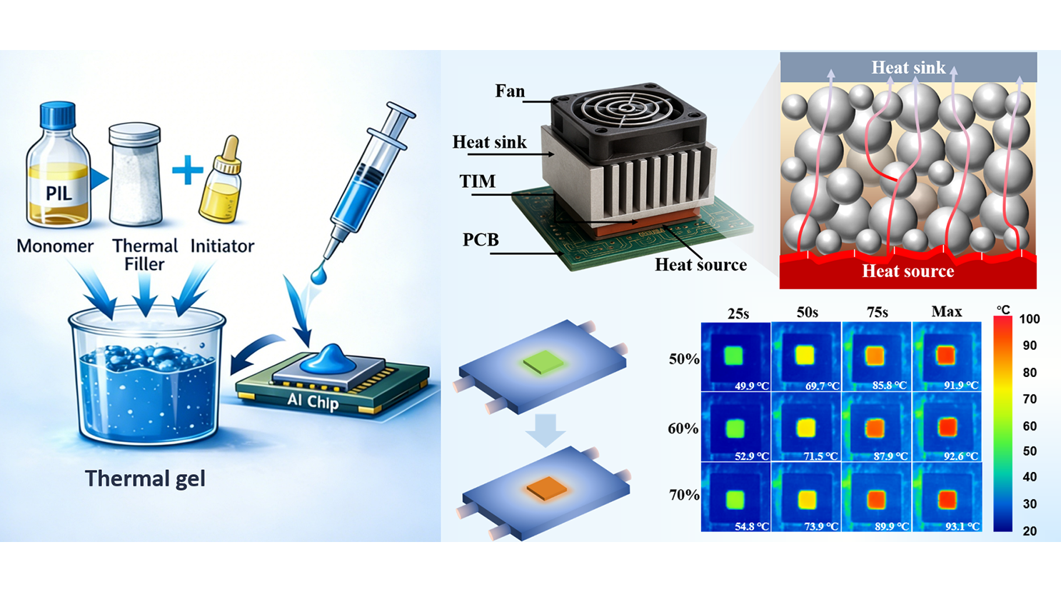
The increasing die size, package dimensions and operating heat flux of AI chips impose stringent requirements on the mechanical compliance and reliability of chip-level thermal interface materials (TIMs). Polymer-based TIMs, particularly silicone gels, offer advantages such as mechanical flexibility, automated dispensability, and warpage accommodation in large packages; however, their application is limited by weak interfacial adhesion and siloxane volatilization. Therefore, it is essential to develop advanced non-silicone thermal gels. This study reports a poly(ionic liquid) (PIL)-based thermally gel TIM. The TIM was fabricated by dispensing a mixture of ionic liquid monomer, Al2O3 thermal filler, and initiator, followed by thermal curing, making it compatible with FCBGA dispensing processes (the viscosity before curing was 225 Pa·s). With 70 vol% Al2O3 filler, the PIL-based TIM exhibited a low storage modulus of 255 kPa and high interfacial adhesion strengths of 0.95 MPa to Cu and 0.91 MPa to Si. The intrinsic thermal resistance reached 2.4 × 10⁻⁵ m2·K/W, comparable to that of conventional silicone systems. Notably, the interfacial contact thermal resistance with Si (Rc = 1.95 ± 0.87 × 10⁻⁷ m2·K/W) was an order of magnitude lower than that of silicone-based TIMs. Reliability tests showed > 98% coverage after three accelerated aging tests, with no leakage or volatilization. The proof-of-concept study validates the feasibility of PIL-based TIMs and highlights their significant potential for further optimization in next-generation AI thermal management.
Graphical Abstract
Keywords
Thermal interface material, thermal gel, poly(ionic liquid), interfacial adhesion, thermal resistance, modulus
1. Introduction
As AI computing performance continues to scale, chip dimensions and areal power density increase in tandem[1-3]. State-of-the-art AI accelerators now exhibit thermal design powers approaching or exceeding 1 kW, with die areas expanding to ~103 mm2, resulting in markedly elevated heat flux densities[4-6]. These extreme thermal loads and large form factors induce pronounced die-package warpage during thermal cycling, which often reaches tens to hundreds of micrometers, with the most severe deformation near die edges. Such deformation amplifies stress concentration and the risk of thermomechanical fatigue failure. Accordingly, chip-scale thermal interface materials (TIMs)[7,8] are required to possess a sufficiently low modulus to accommodate large warpage-induced deformation and strong interfacial adhesion to suppress delamination under cyclic loading, thereby maintaining a stable thermal conduction pathway[9-12].
Silicone-based[13-20] thermal gels, widely used as dispensable gap fillers, offer good process compatibility, mechanical compliance, simple fabrication and low cost. However, their intrinsically low thermal conductivity results in an overall thermal resistance typically exceeding 0.05 K cm2 W-1, and prolonged exposure to high-temperature often leads to material hardening. Oriented
Polymer-based TIMs[32-37] are dominated by silicone formulations due to their high flexibility and chemical stability. Despite decades of optimization, the performance remains intrinsically constrained. Specifically, silicone backbones exhibit weak interfacial interactions with common substrates. To improve their adhesion, promoters are typically required, but that will inevitably increase the elastic modulus, and preclude the simultaneous realization of low modulus and strong adhesion. At a fundamental level, silicone systems rely on covalent crosslinking or physical chain entanglement to balance mechanical compliance and interfacial conformity, resulting in an inherent trade-off between softness and adhesion. Moreover, low-molecular-weight siloxanes (D3-D10) must be reduced through repeated distillation, which increases manufacturing cost while failing to fully eliminate these species. Consequently, volatile siloxane release and oil bleeding remain persistent concerns. In previous work[38-43], poly(ionic liquid) was shown to combine strong interfacial wetting and adhesion with highly designable ionic architectures, indicating their potential as replacements for silicone-based materials. In poly(ionic liquid) TIMs, ionic interactions can dynamically rupture and reform under strain, while localized stresses are effectively attenuated through ion migration. Consequently, the TIMs function as intrinsically stress-adaptive layers rather than purely passive load-bearing medium, showing a mechanical response challenging to achieve with conventional silicone-based TIMs.
Contact thermal resistance (Rc) represents the contact thermal resistance of the interface. The contact thermal resistances on both sides of the thermal interface material are Rc1 and Rc2 respectively, while thermal interface material resistance (RTIM) represents the total thermal resistance of the thermal interface material. RTIM = Rbulk + Rc1 + Rc2, Rbulk represents the intrinsic thermal resistance of the material. Currently, most research focus on the improvement of thermal conductivity of TIM, namely κTIM, thus lead to a reduced RTIM by overlooking Rc1 and Rc2. The contact thermal resistances Rc1 and Rc2 are related to the surface roughness of the interface, the material thermal conductivity and hardness, the modulus of Young's, wettability and other properties[44].
In this work, a solvent-free poly(ionic liquid) (PIL)-based thermal gel was presented. A dual-confinement network comprising ionic and covalent bonds, together with a dynamically reconfigurable ionic network, introduced an additional design parameter for tuning TIM properties, achieving the coexistence of low modulus and high adhesion performance. An ionic liquid monomer bearing vinyl groups was used as the polymerizable matrix, with Al2O3 particles as thermally conductive fillers. Upon mixing with an initiator, a dispensable formulation was obtained and then cured into a TIM at 85 °C for 3 h after lid attachment. To strengthen filler–matrix interactions, Al2O3 surfaces were prefunctionalized with vinyl groups, enabling covalent bonding with the PIL matrix. Thermally initiated polymerization of the vinyl-functional monomers allowed a one-step curing process, yielding a highly processable composite paste suitable for precise dispensing and controlled deposition (Scheme 1). At the Al2O3 loading of 70 vol%, the formulation exhibited a viscosity of 225 Pa·s at a shear rate of 5 s-1, compatible with cartridge filling and standard dispensing processes. Compared with conventional silicone-based systems, the PIL gel cured at a lower temperature and was storable at room temperature without refrigeration. The intrinsic thermal resistance reached 2.4 × 10⁻⁵ m2·K/W, comparable to that of silicone TIMs. Owing to synergistic electrostatic, hydrogen-bonding, and ion-dipole interactions at the interface, the cured TIM containing 70 vol% Al2O3 exhibited an interfacial adhesion strength of 0.91 MPa and an interfacial contact thermal resistance of Rc = 1.95 ± 0.87 × 10⁻⁷ m2·K/W on Si substrates, substantially outperforming silicone counterparts. By comparison, a commercial silicone TIM (Shin-Etsu X-23-7772-4) showed an adhesion strength below 0.08 MPa and Rc = 2.61 ± 0.50 × 10⁻⁶ m2·K/W on Si. The cured PIL gel exhibited a storage modulus of 255 kPa, comparable to typical silicone-based TIMs (~200 kPa). Reliability was evaluated using Si–TIM–Si dummy structures subjected to high-temperature storage (150 °C, 300 h), damp heat (85 °C/85% RH, 150 h), and thermal shock cycling (-50 to 150 °C,
Scheme 1. Development and preparation of thermal gel for poly(ionic liquid) dispensing systems.
2. Methods
2.1 Materials
Sulfuryl chloride, triethylene, chloroform, trichloromethane, ethylene glycol monomethyl ether, pyridine, anhydrous magnesium sulfate, N-Vinylimidazole, ethyl ether, lithium bis(trifluoromethanesulfonyl)imide, ethanol, poly(ethylene glycol) diacrylate, and vinyl triethoxy silane were purchased from Millipore Chemicals. Spherical alumina was obtained from Jiangsu Lianrui New Materials Company.
2.2 Experimental details
2.2.1 Synthesis of VIm-3EO NTf2
Mix 0.45 mol of sulfuryl chloride solvent with 90 mL of chloroform. Slowly add this mixture to the solution of triethylene glycol monomethyl ether (0.45 mol), pyridine (0.3 mol), and chloroform (200 mL) over a period of 60 minutes. Stir the resulting mixture in an oil bath at 100 °C for 4 hours, yielding a yellow turbid solution. Wash it four times with pure water, and dry over anhydrous MgSO4. Perform vacuum distillation at 60 °C to remove chloroform. Purify the crude product under vacuum to obtain
2-[2-(2-methoxyethoxy)ethoxy]ethyl chloride and N-ethyleneimine were reacted at a molar ratio of 1:1 at 100 °C for 72 hours. After the reaction, the mixture was washed with ether to remove unreacted impurities and dried in an oven. Subsequently, it was subjected to ion exchange with lithium bis(trifluoromethanesulfonyl)imide in a water solution at a molar ratio of 1:1. Following the exchange, the mixture underwent liquid-liquid separation and drying to obtain the 1-ethylene-3-1-(2-(2-(2-ethoxyethoxy)ethoxy)ethyl)-3-ethylene-imidazole bis(trifluoromethanesulfonyl)imide salt product.
2.2.2 Preparation of modified Al2O3
The purchased Al2O3 powder was ultrasonically cleaned with anhydrous ethanol for 30 minutes to remove the adsorbed organic substances, and then dried in a vacuum at 150 °C for 12 hours to eliminate residual moisture. The vinyl triethoxy silane: water: ethanol volume ratio was set at 1:5:30 for mixing and the mixture was hydrolyzed at 60 °C for one hour. Then, the pre-treated activated Al2O3 powder was dispersed in the hydrolyzed mixed solvent, with a small amount of acetic acid added to maintain the weak acidity of the solvent. The reaction temperature was adjusted to 80 °C for 6 hours of mechanical stirring. Subsequently, the modified mixture was centrifuged to separate the activated Al2O3, washed with ethanol until neutral, and dried in a vacuum oven at 80 °C for 24 hours to yield the modified Al2O3 powder raw material.
2.2.3 Preparation of thermal gel
First, mix the crosslinking agent, initiator and ionic liquid monomer in a ratio of 1:1:200 to obtain the initial mixture. Then, respectively mix the modified Al2O3 at volume ratios of 50%, 60% and 70% with the mixture, and mix them in a vacuum mixer at a speed of 1,500 ppm for 2 minutes. Inject the uniformly mixed thermal gel into a syringe for further vacuum defoaming treatment. After that, inject it into the mold and place it in an oven for curing at 85 °C for 3 hours to obtain TIM.
2.3 Characterization
The 1H NMR spectra were recorded on a Bruker 400 MHz spectrometer, using TMS as the internal reference. Attenuated total reflectance infrared (ATR-IR) spectra were recorded using a Fourier transform infrared (FTIR) spectrometer equipped with a diamond single-reflection ATR accessory. Thermogravimetric analysis (TGA) was conducted based on an SDT650 thermal analysis system (TA Instruments, USA) at a heating rate of 5 °C min-1 under both air and N2 atmospheres. Mechanical testing was carried out at room temperature using a universal tensile testing machine (AGX-10kNVD, Shimadzu) in accordance with ASTM D412. Dynamic viscoelastic properties of the composites were characterized using an Anton Paar MCR-302 rheometer. Frequency sweep tests were performed over an angular frequency (ω) range of 0.1-100 rad s-1 at specified temperatures. Temperature sweep measurements were conducted from 25 to 180 °C at a heating rate of 5 °C/min, with a fixed angular frequency of 5 Hz and a shear strain (γ) of 1%. Adhesion strength was evaluated using a DAGE 4000HS high-speed multi-function weld strength tester. Dynamic mechanical analysis (DMA) and compressive stress–strain tests were performed using a TA Instruments RSA-G2 solids analyzer on square-shaped samples. In the DMA test, the composites were first compressed to 90% of their original thickness, and the compressive modulus was subsequently measured. They were then held for 15 min, followed by 15 min of stress relaxation, after which the rebound degree was measured. Sample morphologies and elemental distributions were analysed using scanning electron microscopy (SEM, Apreo 2S, Thermo Fisher Scientific) and energy-dispersive spectroscopy (EDS, Oxford Unity BEX). The samples after curing were examined by Micro CT using the Zeiss Xradia 620 Versa three-dimensional X-ray microscope. X-ray photoelectron spectroscopy (XPS) was performed using an ESCALA instrument (Thermo Fisher Scientific). The X-ray Cheetah-EVO equipment produced by German company YXLON was used to conduct flaw detection on sandwich structure samples. The structure of the sample was scanned with the American Sonoscan ultrasonic scanning microscope D9600 C-SAM. Through-plane thermal diffusivities of the PIL/Al2O3 composites were measured at
where α is the thermal diffusivity, ρ is the density, and Cp is the specific heat capacity of composites. Density was measured using the buoyancy method (SUNNY HENGPING, FA2104J, China), while Cp was determined by the sapphire method and calculated from differential scanning calorimetry (DSC) data. Thermal resistance and heat dissipation of the chip under practical conditions were simulated using a T3ster thermal resistance tester (Mentor Graphics). The total thermal resistance of the system is expressed by the formula:
2.4 Frequency Domain Thermoreflectance (FDTR) measurement
The configuration of the low-frequency FDTR system employed in this study is described as follows. A 532 nm green laser with a power of about 110 mW served as the probe beam, and a gold (Au) coating as the transducer. The pump source was a 457 nm blue laser delivering up to 1.5 W of energy, with roughly 60% of the incident power absorbed by the sample. Its modulation was controlled by a lock-in amplifier through an acousto-optic modulator, with a frequency ranging from 10 Hz to 100 kHz. Continuously adjustable neutral density (ND) filters were placed in both the pump and probe paths to precisely regulate laser power and maintain optimal measurement conditions. Prior to measurements, a sensitivity analysis was conducted to identify parameters measurable with high confidence and to select the appropriate modulation frequencies.
In FDTR, the periodically modulated pump beam induces a frequency-dependent surface temperature oscillation detected via
where f is the modulation frequency, α is the thermal diffusivity, k is the thermal conductivity, and C is the volumetric heat capacity. The TPD is defined as the characteristic depth at which the amplitude of the temperature oscillation decays to 1/e of its surface value under periodic heating.
As the thermal penetration depth depends on modulation frequency, the phase sensitivity to each parameter also varies with frequency. In this study, the sensitivity of phase to a parameter x is defined as follows.
The sensitivity curves are determined by the thermal model and are influenced by other inputs, such as laser spot sizes, sample structure, volumetric heat capacity, thermal conductivity, and contact resistance. When the sensitivity peaks of k and Rc do not overlap, multi-frequency fitting enables their effective decoupling. In our low-frequency FDTR results, the sensitivity peak of k occurs at lower frequencies than that of Rc.
3. Results and Discussion
As shown in Figure 1, the adhesive materials for the composites mainly consist of surface-modified alumina (Al2O3), VIm-3EO NTf2, and poly(ethylene glycol) diacrylate (PEGDA) as the crosslinking agent. The vinyl-functionalized imidazolium ionic liquid monomer
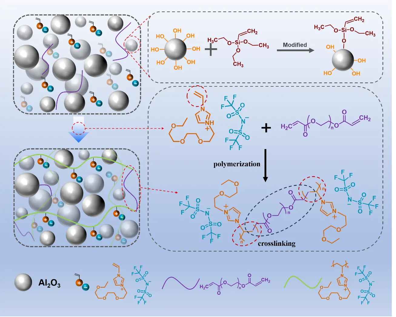
Figure 1. Schematic diagram of the composite preparation process. Vinyl ionic liquid is blended with modified Al2O3, an appropriate crosslinking agent is introduced, and the composite is obtained after polymerization.
Figure 2a presents the 1H nuclear magnetic resonance (1H NMR) spectrum of the VIm-3EO NTf2, where characteristic peaks (labeled a–g) correspond to distinct proton environments within the molecular framework. For instance: signals at ~5.0-6.0 ppm (Figure 2d,e) are attributed to vinyl (-CH=CH2) protons, confirming the presence of polymerizable double bonds. Multiplets at ~7.0–10.0 ppm
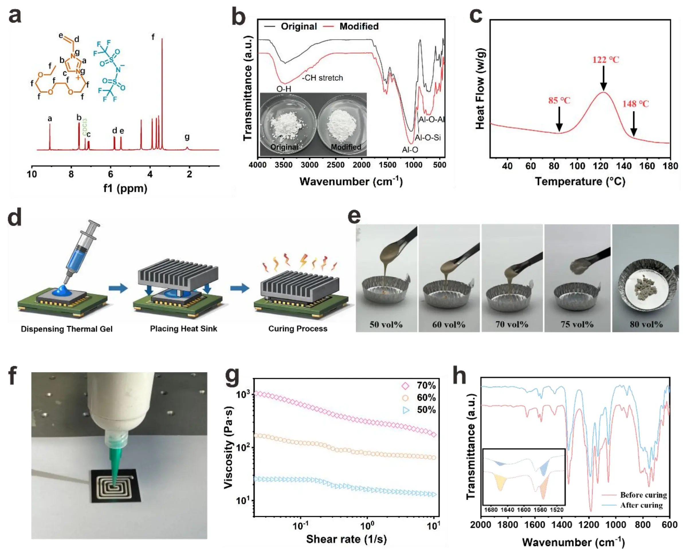
Figure 2. (a) 1H NMR spectrum (CDCl3) of VIm-3EO NTf2; (b) Infrared spectra of Al2O3 before and after modification; (c) The DSC heat flow curve during the gel curing process of 70 vol% filler; (d) Dispensing process schematic diagram; (e) Optical images of mixtures with different volume fractions; (f) Optical image of the dispensing of 70 vol% mixture; (g) The viscosities of mixtures with different volume fractions before curing; (h) 70 vol% thermal gel before and after curing's infrared spectrum. NMR: nuclear magnetic resonance; DSC: differential scanning calorimetry.
X represents the conversion rate of the sample, while
The optical images in Figure 3a reveal the composite’s excellent mechanical flexibility under twisting and bending, even at high volume fractions. The composites maintain structural integrity under large deformations, indicating substantial ductility and strain tolerance, critical for applications in flexible electronics, wearable devices, and adaptive bonding systems. This flexibility originates from the well-integrated matrix-filler interface, where interfacial interactions effectively dissipate stress during deformation. Composites with volume fractions of 50% and 70% both exhibit stable deformability. This further indicates that they have good phase compatibility, enabling them to deform without fracturing under mechanical stress and to resist potential material failure caused by such stress. A Micro CT examination was conducted on the 70 vol% composite (Figure 3b), and the three-dimensional views of the composite were presented. The right figure shows the cross-sectional slice of the composite. It was found that the distribution of
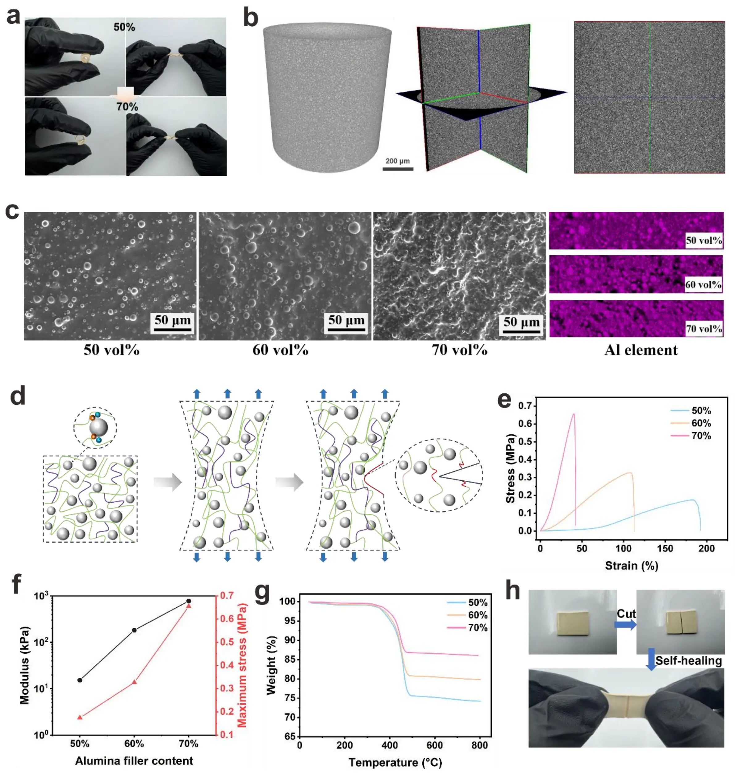
Figure 3. (a) Optical images of the composites with volume fractions of 50% and 70% under twisting and bending deformations; (b) Micro CT image of 70 vol% composite;
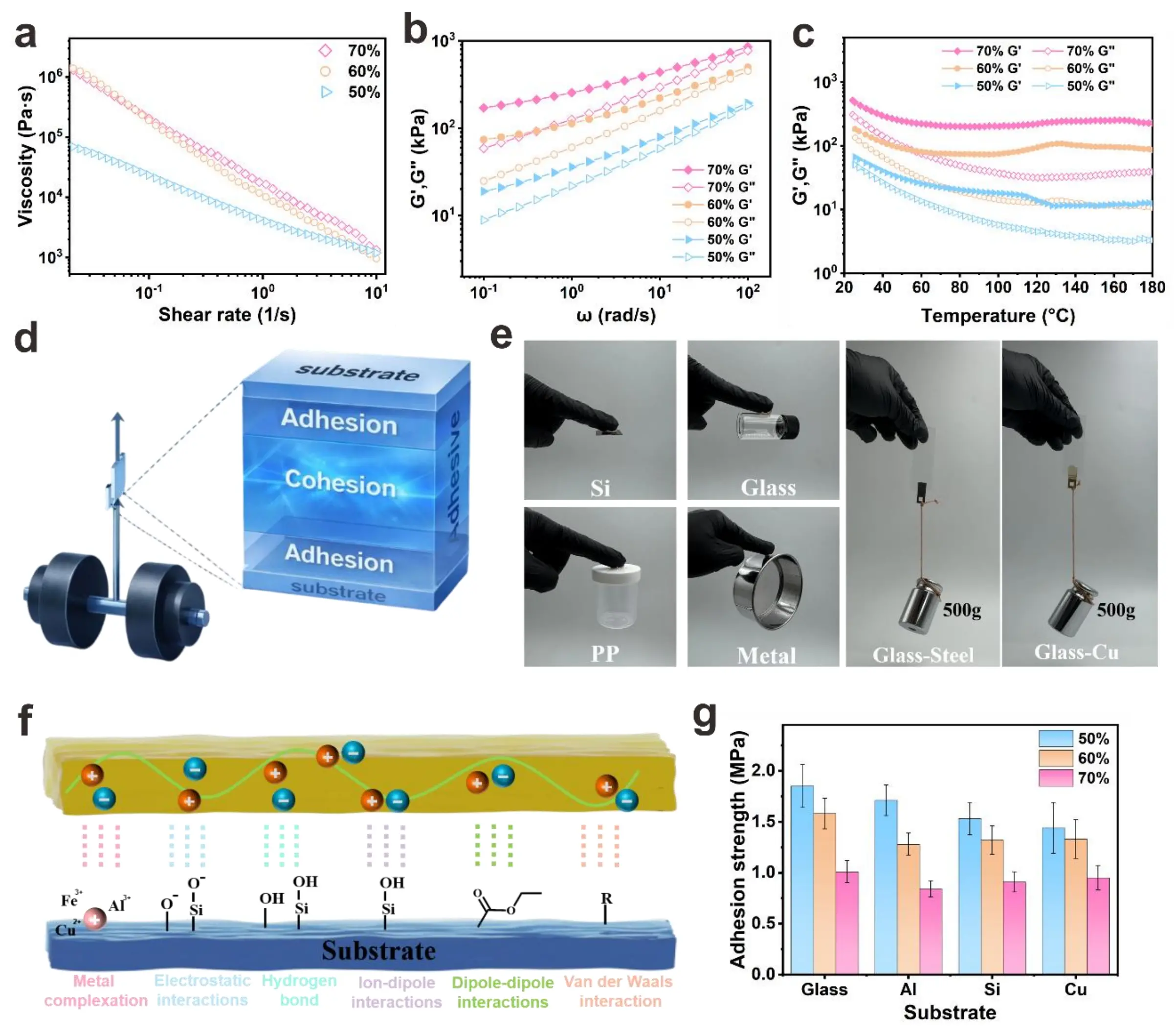
Figure 4. (a) The viscosities of mixtures with different volume fractions after curing; (b) the frequency dependence and (c) temperature dependence of the storage modulus and loss modulus; (d) Schematic of adhesion; (e) Optical demonstrations of the composite’s adhesion to diverse substrates and the load-bearing capacity of Glass-Steel and Glass-Cu bonded joints; (f) Schematic illustration of the multi-mechanism adhesion between the composite and substrates; (g) Adhesion strength of the composite with different volume fractions at room temperature on various substrates.
Notably, cured composites exhibit orders-of-magnitude higher viscosity than their uncured counterparts (Figure 4a), attributed to the formation of a crosslinking-induced network that restricts molecular mobility. This effect becomes more pronounced with higher volume fractions due to enhanced particle–matrix interactions and physical entanglement. The complex viscosity (η*) (Figure S14) mirrors the shear viscosity trends: η* increases with volume fraction and decreases with angular frequency (ω), consistent with shear-thinning behavior. Frequency sweeps (Figure 3b) reveal that the storage modulus (G’), representing elastic energy storage, consistently exceeds the loss modulus (G’’) (viscous energy dissipation) across the tested range. This G’ > G’’ relationship confirms a predominantly elastic, gel-like network, which is essential for structural integrity post-dispensing. At higher volume fractions (e.g.,
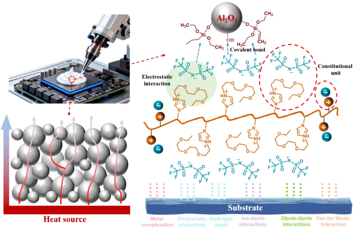
The thermal gel used in this work has excellent adhesion properties (Figure 4d). These properties enhance the ability of the TIM to maintain good interfacial contact under complex thermal and mechanical stresses in actual working conditions. Figure 4e demonstrates the composite’s broad substrate compatibility, displaying robust bonding to inorganic (Si, Glass, Metal) and organic (PP) surfaces. The successful adhesion to chemically distinct substrates highlights the composite’s adaptability to diverse surface chemistries. Notably, the Glass-Steel and Glass-Cu joints support a 500 g load, experimentally validating the composite’s practical adhesive capacity. The multi-mechanism adhesion schematic (Figure 4f) explains the molecular origins of strong adhesion. Metal complexation occurs through the formation of coordinate bonds between metal cations (e.g., Fe2+, Al3+, Cu2+) on metallic substrates and anionic groups (e.g., O2-, Si-O-) in the composite. Electrostatic interactions arise from attractive forces between charged species on the composite and substrate surfaces. Hydrogen bonding further contributes to adhesion via strong interactions between hydroxyl (-OH) groups (abundant on Glass/Si) and polar functional groups in the composite. Ion-dipole/dipole-dipole interactions provide long-range forces between ionic species/dipoles in the composite and substrate. Van der Waals interactions, as universal intermolecular forces, enhance interfacial adhesion. This synergistic combination of specific (e.g., hydrogen bonding, metal complexation) and nonspecific (van der Waals) interactions forms a robust bonding network, accounting for the composite’s strong and durable adhesion. Figure 4e quantifies adhesion strength across substrates and volume fractions. Glass exhibits the highest adhesion strength, with values of 1.85 ± 0.21 MPa, 1.58 ± 0.15 MPa and 1.01 ± 0.11 MPa for 50, 60, and 70 vol%, respectively. This is attributed to its dense -OH groups that form extensive hydrogen bonds with the composites. Al, Si, and Cu show moderate yet still substantial strengths. The 50 vol% composite generally outperforms 60 vol% and 70 vol% counterparts. At 70 vol%, excessive filler may induce agglomeration, reducing effective interfacial contact and weakening matrix connectivity before lowering adhesion. Figure S15 presents the interfacial adhesion strength of the 70 vol% thermal gel during the test at different temperatures. The results indicate that as the temperature increases, the interfacial adhesion strength decreases significantly at 50 °C, but remains above 0.1 MPa at temperatures below 175 °C, maintaining a weak interfacial adhesion strength. The main reasons for the attenuation of the interface adhesion strength of composites under high temperature may be as follows: (1) The Tg of PILs decreases under high temperature, and the chain segments undergo viscous flow. Under thermal stress, relative slippage at the interface may occur, and macroscopically, the interface shear strength fails. (2) High temperature intensifies the mobility of PIL chain segments, disrupting the polar matching between the ionic groups and the polar surfaces of inorganic/organic fillers, thus resulting in a sharp decline in interface compatibility.
Thermal management performance under practical operating conditions was evaluated using a T3ster system (Figure 5a). A constant power was applied to heat the ceramic sheet, and the prepared samples were used to fill in the space between the heat sink and the heated ceramic sheet to promote heat transfer. Figure 5b depicts the temperature evolution for samples without TIM and with TIMs at different volume fractions: the sample without TIM exhibits a rapid temperature rise to over 120 °C, whereas TIM-integrated samples show markedly lower temperatures, with the 70 vol% TIM sample maintaining the lowest temperature. This demonstrates that the composite TIM effectively accelerates heat dissipation from the heat source. The steady-state temperature as a function of power density (Figure 5c) further quantifies this performance: as power density increases, samples with higher filler contents exhibit a significantly slower temperature rise, confirming their superior capability to manage high heat fluxes.
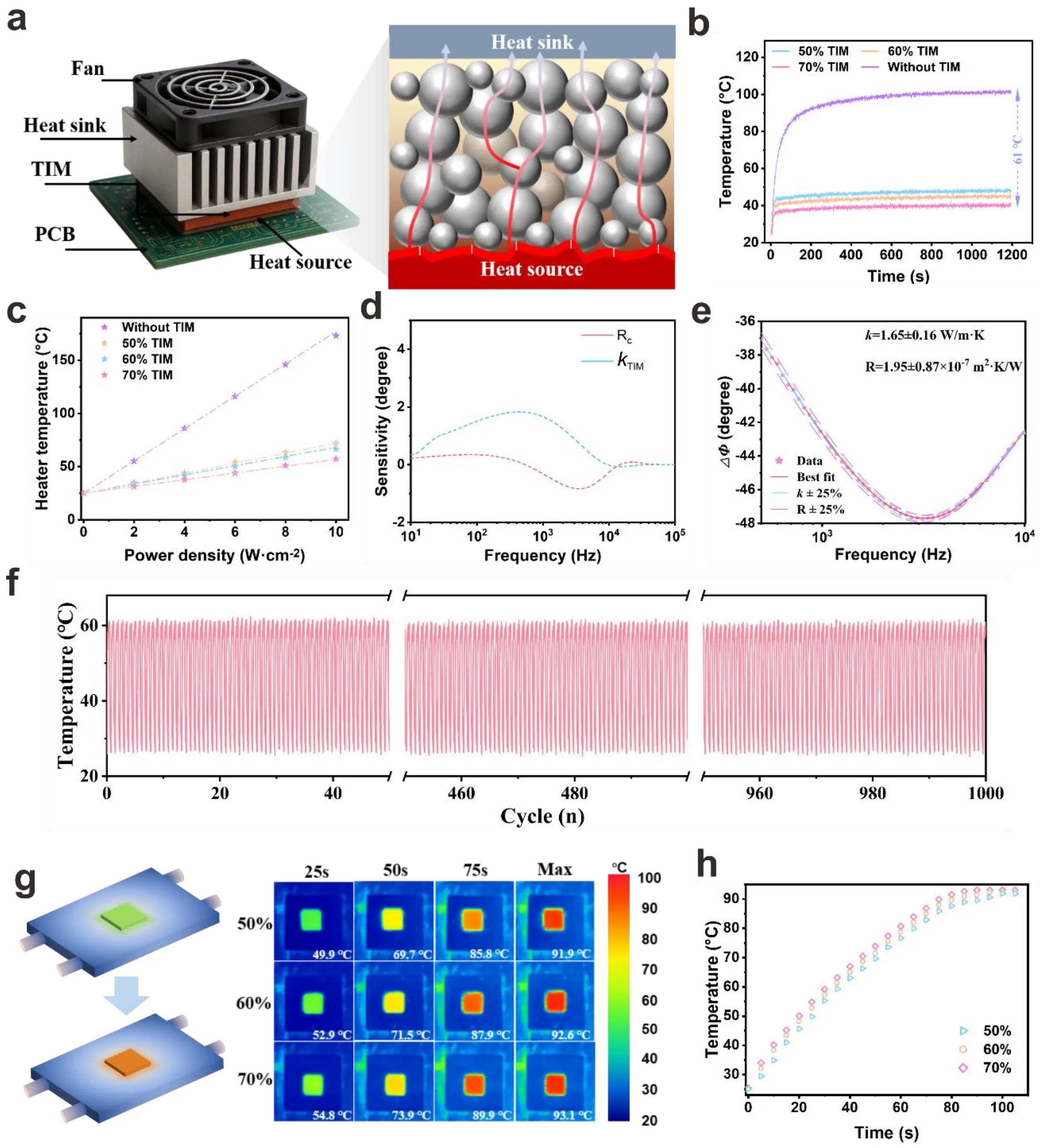
Figure 5. Thermal management performance of composites with varying filler volume fractions. (a) The schematic diagram of the T3ster system and the heat transfer diagram of the thermal gel. The temperature of the chip varies with the (b)working time and (c) different input powers; (d)The sensitivity analysis of the FDTR test and the (e) test results of 70 vol% TIM; (f) The results of 1,000 heating-cooling temperature cycles of 70% TIM solution; (g) The thermal infrared images of different filler contents TIM on the heating device and (h) changes in surface temperature over time. FDTR: Frequency Domain Thermoreflectance; TIM: thermal interface material.
Thermal conductivity and thermal diffusivity are two fundamental thermal properties that control the steady-state and transient response of materials under thermal load. Accurate measurement of these parameters is critically important, and is affected by many factors, such as the physical characteristics of the sample, ambient temperature, and its intrinsic thermal conductivity and diffusivity. Although steady-state methods can measure thermal conductivity by applying a constant heat flux and measuring the corresponding temperature gradient, these approaches are usually laborious and require precise control of heating and boundary conditions. In contrast, transient techniques, which record the time-domain or frequency-domain response of materials under pulsed or periodic thermal excitation, provide a simpler and more efficient way to determine thermal conductivity and thermal diffusivity rapidly and reliably[45-47]. To further elucidate the thermal transport mechanisms, FDTR measurements were conducted. The sample structure for the FDTR test and the corresponding schematic diagram are shown in Figures S16,S17. The sensitivity analysis (Figure 5d) illustrates the frequency dependence of the sensitivities to interface thermal resistance (Rc) and thermal conductivity (κTIM), revealing that FDTR can resolve their respective contributions within the tested frequency range (101-106 Hz). The experimental FDTR results (Figure 5e) yield = 1.65 ± 0.16 W/m·K and Rc = 1.95 ± 0.87 × 10⁻⁷ m2·K/W, which are consistent with the bulk thermal conductivity in Figure S18. The BLT in this work is approximately 40 μm, and according to the formula
A self-consistent test by using the FDTR method used in this paper to test both PIL/Al2O3 samples and the commercial TIM. For comparison, the interface thermal resistance of the commercial thermal gel was tested using the same standard, with the results shown in Figures S19,S20. The interface thermal resistance of the commercial gel is 2.61 ± 0.50 × 10⁻⁶ m2·K/W, which means that the interface thermal resistance of the thermal gel in this study is approximately one order of magnitude lower than that of the commercial gel. Table 1 compares the BLT and Rc values of typical thermal interface materials, demonstrating the significant advantages of PIL/Al2O3.
Table 1. Comparison of BLT and Rc in TIMs.
| Materials | BLT (μm) | Rc (mm2·K/W) | References |
| PIL/Al2O3 | ~40 | 0.195 | This work |
| Shin-Etsu X-23 | ~40 | 2.61 | |
| PDMS/Al2O3 | 100 | 40 | [36] |
| PDMS/Al2O3/ZnO | 11.41 | 1.50 | [48] |
| Silicone/GNP | 130 | 40.1 | [49] |
| Graphene/SiC | 250 | 47 | [50] |
| VAGM | 800 | 54–82 | [51] |
BLT: bond line thickness; PDMS: polydimethylsiloxane; PIL: poly(ionic liquid); GNP: graphene nanoplatelets; VAGM: vertically aligned graphene film; TIMs: thermal interface materials;
This consistency validates both the reliability of the FDTR technique and the composite’s balanced intrinsic thermal conductivity and interface thermal resistance. Thermal cycling stability is critical for long-term reliability. As shown in Figure 5f, the 70 vol% TIM sample undergoes 1,000 heating–cooling cycles without noticeable degradation in its temperature profile, indicating excellent thermal cycle stability. This robustness ensures the composite’s reliability during prolonged operation under periodic heat loads. Infrared (IR) thermal imaging (Figure 5g,h) provides direct visualization of temperature distribution and its temporal evolution.
To further verify the reliability and industrial applicability of the samples, 70 vol% TIM was used to fabricate sandwich-structured samples. The uncured sample was drop-cast onto a silicon wafer, subsequently covered with a 1 × 1 cm silicon wafer, and then cured
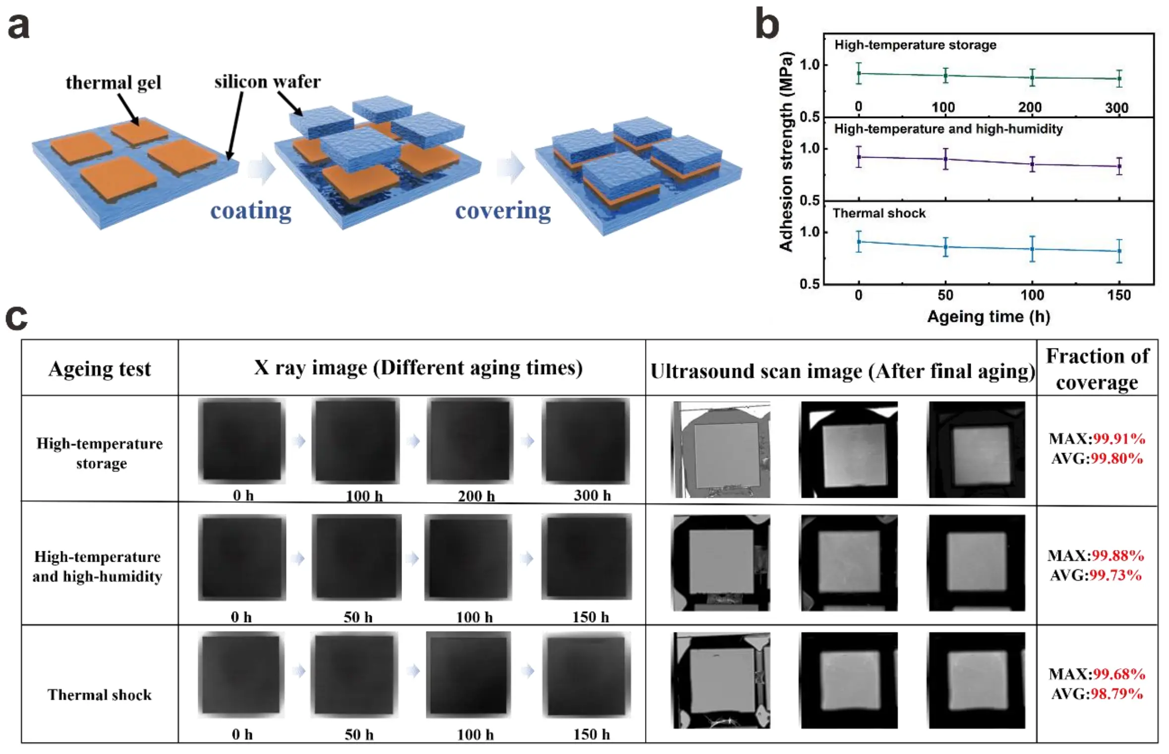
Figure 6. (a) Schematic diagram of the sandwich sample structure preparation; (b)The interfacial adhesion strength obtained from the three accelerated aging experiments; (c) Images of the sample after undergoing three accelerated aging experiments taken by X-ray and the ultrasonic scanning images of the three aging samples after the longest aging period.
4. Conclusions
In conclusion, this study presents a novel thermal gel based on a PIL matrix and filled with Al2O3 particles, offering a new material strategy for high-performance thermal interface materials. The PIL matrix possesses inherent ionic cross-linking and high flexibility. The addition of the Al2O3 filler effectively constructs a continuous thermal conduction path, significantly improving the thermal conductivity while maintaining mechanical flexibility and adhesion strength (0.95 MPa with Cu and 0.91 MPa with Si). Comprehensive characterization has demonstrated the excellent performance of the PIL/Al2O3 thermal gel in rheological properties suitable for dispensing applications (225 Pa·s), thermal stability, low interface thermal resistance (Rc = 1.95 ± 0.87 × 10⁻⁷ m2·K/W), mechanical properties, and anti-aging performance (the coverage rates after the three aging tests were all above 98%.). This work not only validates the feasibility of PIL as a new-generation matrix for TIM, but also establishes a molecular design framework that balances thermal and mechanical properties by integrating ionic interactions and filler engineering. These results provide valuable insights into the development of TIM1 such as thermal gel for next-generation electronic devices. Although the overall performance of the PIL-based thermally gel has not yet surpassed that of conventional silicone systems, this work validates the feasibility of this technological approach and highlights its potential for practical applications. Future research will focus on molecular structure optimization and the incorporation of functional additives to further enhance material properties and explore the performance limits of polymer-based TIMs.
Supplementary materials
The supplementary material for this article is available at: Supplementary materials.
Authors contribution
Zeng J: Data curation, formal analysis, investigation, writing-original draft.
Rao T: Formal analysis, visualization, methodology.
Shi H, Guo Y: Formal analysis, methodology.
Peng Z, Li L: Resources, supervision, validation.
Sun R: Supervision, funding acquisition, project administration, validation.
Yao Y: Conceptualization, funding acquisition, project administration, writing-original draft, writing-review & editing.
Conflicts of interest
The authors declare no potential conflict of interest exists.
Ethical approval
Not applicable.
Consent to participate
Not applicable.
Consent for publication
Not applicable.
Availability of data and materials
The data that support the findings of this study are available from the corresponding author upon reasonable request.
Funding
This work was supported by National Natural Science Foundation of China (No. 62474116), CAS Proiect for Young Scientists in Basic Research (No. YSBR-105), National Key R & D Program of China (No. 2022YFA1203100), Autonomous deployment project of China National Key Laboratory of Materials for Integrated Circuits (No. SKLJC-Z2025-A08), GuangDong Basic and Applied Basic Research Foundation (No. 2025A1515012967), and Beijing Natural Science Foundation (No. L257012.
Copyright
© The Author(s) 2026.
References
-
1. Hu R, Liu Y, Shin S, Huang S, Ren X, Shu W, et al. Emerging materials and strategies for personal thermal management. Adv Energy Mater. 2020;10(17):1903921.[DOI]
-
2. Li Y, Li W, Han T, Zheng X, Li J, Li B, et al. Transforming heat transfer with thermal metamaterials and devices. Nat Rev Mater. 2021;6:488-507.[DOI]
-
3. Dang H, Lu Y, Du Y, Zhang X, Zhang Q, Ma W, et al. A detailed thermal resistance network analysis of FCBGA package. J Therm Sci. 2024;33(1):18-28.[DOI]
-
4. Xing W, Xu Y, Song C, Deng T. Recent advances in thermal interface materials for thermal management of high-power electronics. Nanomaterials. 2022;12(19):3365.[DOI]
-
5. Sui Z, Sui Y, Ding Z, Lin H, Li F, Yang R, et al. Membrane-encapsulated, moisture-desorptive passive cooling for high-performance, ultra-low-cost, and long-duration electronics thermal management. Device. 2023;1(6):100121.[DOI]
-
6. Peng J, Deng C, Wei F, Ding S, Hu R, Luo X. A hybrid thermal management system combining liquid cooling and phase change material for downhole electronics. J Energy Storage. 2023;72:108610.[DOI]
-
7. Chen H, Zheng F, Cheng W, Tao P, Song C, Shang W, et al. Low thermal expansion metal composite-based heat spreader for high temperature thermal management. Mater Des. 2021;208:109897.[DOI]
-
9. Chen J, Xu X, Zhou J, Li B. Interfacial thermal resistance: Past, present, and future. Rev Mod Phys. 2022;94(2):025002.[DOI]
-
10. Liu B, Dong L, Xi Q, Xu X, Zhou J, Li B. Thermal transport in organic/inorganic composites. Front Energy. 2018;12(1):72-86.[DOI]
-
11. Qi J, Liang C, Ruan K, Li M, Guo H, He M, et al. Cactus-like architecture for synergistic microwave absorption and thermal management. Natl Sci Rev. 2025;12(11):nwaf394.[DOI]
-
13. Huang C, Qian X, Yang R. Thermal conductivity of polymers and polymer nanocomposites. Mater Sci Eng R Rep. 2018;132:1-22.
-
14. Zhang X, Xie B, Zhou S, Yang X, Fan Y, Hu R, et al. Radially oriented functional thermal materials prepared by flow field-driven self-assembly strategy. Nano Energy. 2022;104:107986.[DOI]
-
15. Lei Z, Song C. Temperature-dependent adhesive polymer-based composites with shape adaptability and low thermal contact resistance for thermal management. Mater Today Commun. 2023;34:105164.[DOI]
-
17. Guo Y, Xu K, Wang Y, Zhang Z, Gong P, Zhang J, et al. Light weight organic composites with high thermal management capability. Nano Lett. 2025;25(9):3405-3413.[DOI]
-
18. Guo Y, Zhang L, Ruan K, Mu Y, He M, Gu J. Enhancing hydrolysis resistance and thermal conductivity of aluminum nitride/polysiloxane composites via block copolymer-modification. Polymer. 2025;323:128189.[DOI]
-
19. Guo Y, Ruan K, Shi X, Yang X, Gu J. Factors affecting thermal conductivities of the polymers and polymer composites: A review. Compos Sci Technol. 2020;193:108134.[DOI]
-
20. Mehra N, Mu L, Ji T, Yang X, Kong J, Gu J, et al. Thermal transport in polymeric materials and across composite interfaces. Appl Mater Today. 2018;12:92-130.[DOI]
-
21. Xu K, Zhang Z, Wang Y, Li M, Chen Y, Kong X, et al. Sandwich-structured thermal interface materials with high thermal conductivity. ACS Appl Eng Mater. 2024;2(6):1572-1581.[DOI]
-
22. Zhang Z, Yang R, Wang Y, Xu K, Dai W, Zhang J, et al. Enhanced thermal conductivity and reduced thermal resistance in carbon fiber-based thermal interface materials with vertically aligned structure. J Mater Chem A. 2024;12(36):24428-24440.
-
23. Qin Y, Zhu B, Li L, Wang Y, Li M, Zhang Z, et al. Dual-functional carbon material possessing light absorption and heat conduction & energy storage. Adv Compos Hybrid Mater. 2025;8(4):313.[DOI]
-
24. Zhang Y, Yang J, Zhang X, Xu R, Liu M, Fan A, et al. Investigation of anisotropic thermophysical properties of highly oriented carbon fiber composites: From one to three dimensions. Carbon. 2025;243:120477.[DOI]
-
25. Liu W, Xu Y, Su Y, Liu Y, Lei Z, Tao P, et al. Multi-functional highly oriented expanded graphite nanoplatelet composites enabling advanced thermal management. Carbon. 2025;243:120588.[DOI]
-
26. Li Z, Wang L, Li Y, Feng Y, Feng W. Carbon-based functional nanomaterials: Preparation, properties and applications. Compos Sci Technol. 2019;179:10-40.[DOI]
-
27. Xu Y, Xing W, Liu J, Song C. Highly thermal conductive and rechargeable 3D liquid metal network-based phase change composite enabling photothermal pad. Compos Commun. 2023;43:101719.[DOI]
-
28. Chu B, Liu B, Fu B, Wang R, Cheng W, Tao P, et al. Self-assembled liquid metal nanoporous film with durability for efficient phase-change thermal energy management via surface and interface engineering. Mater Today. 2024;73:56-65.[DOI]
-
29. Ma X, Zhang H, Guo Y, He M, Guo H, Liu Z, et al. Enhancing thermal conductivity in polysiloxane composites through synergistic design of liquid crystals and boron nitride nanosheets. J Mater Sci Technol. 2025;231:54-61.[DOI]
-
30. Wu K, Dou Z, Deng S, Wu D, Zhang B, Yang H, et al. Mechanochemistry-mediated colloidal liquid metals for electronic device cooling at kilowatt levels. Nat Nanotechnol. 2025;20:104-111.[DOI]
-
32. Zhang K, Zhang J, Dang L, Wu Y, He M, Guo H, et al. High intrinsic thermal conductivity and low dielectric constant of liquid crystalline epoxy resins with fluorine-containing semi-IPN structures. Sci China Chem. 2025;68(6):2615-2627.[DOI]
-
36. Xie Z, Dou Z, Wu D, Zeng X, Feng Y, Tian Y, et al. Joint-inspired liquid and thermal conductive interface for designing thermal interface materials with high solid filling yet excellent thixotropy. Adv Funct Mater. 2023;33(14):2214071.[DOI]
-
37. Zhang F, Feng Y, Feng W. Three-dimensional interconnected networks for thermally conductive polymer composites: Design, preparation, properties, and mechanisms. Mater Sci Eng R Rep. 2020;142:100580.[DOI]
-
38. Zeng J, Liang T, Yang B, Rao T, Han M, Yao Y, et al. Poly(ionic liquid)s: A promising matrix for thermal interface materials. ACS Appl Mater Interfaces. 2024;16(34):45563-45576.[DOI]
-
39. Zeng J, Li X, Liang T, Rao T, Zheng Z, Yao Y, et al. Thermally conductive and self-healable liquid metal elastomer composites based on poly(ionic liquid)s. Compos Part A Appl Sci Manuf. 2025;194:108922.[DOI]
-
40. Zeng J, Rao T, Liang T, Yao Y, Wang C, Xu JB, et al. Poly(Ionic Liquid) matrices embedded with liquid metal particles: A versatile solution for high-power density thermal management. Compos Part A Appl Sci Manuf. 2025;199:109221.[DOI]
-
42. Luo X, Lin Z, Yang B, Rao T, Zeng J, Jiang Y, et al. Poly(ionic liquid)-based thermal interface materials with enhanced interfacial adhesion and thermal stability for advanced electronic cooling. Adv Mater Technol. 2025;10(23):e01321.[DOI]
Copyright
© The Author(s) 2026. This is an Open Access article licensed under a Creative Commons Attribution 4.0 International License (https://creativecommons.org/licenses/by/4.0/), which permits unrestricted use, sharing, adaptation, distribution and reproduction in any medium or format, for any purpose, even commercially, as long as you give appropriate credit to the original author(s) and the source, provide a link to the Creative Commons license, and indicate if changes were made.
Publisher’s Note
Science Exploration remains a neutral stance on jurisdictional claims in published
maps
and institutional affiliations. The views expressed in this article are solely those
of
the author(s) and do not reflect the opinions of the Editors or the publisher.
Share And Cite


Science Exploration Style
Zeng J, Rao T, Shi H, Guo Y, Peng Z, Li L, et al. Poly(ionic liquid) thermal gels enabling compliant and adhesive interfaces for chip-scale thermal management. Thermo-X. 2026;2:202520. https://doi.org/10.70401/tx.2026.0011
Tips
Copy completed.
Submit a Manuscript
Author Instructions
Cite this Article
Article Metrics
0
View
0
Download
Cited
Article Updates

Science Exploration Style
Zeng J, Rao T, Shi H, Guo Y, Peng Z, Li L, et al. Poly(ionic liquid) thermal gels enabling compliant and adhesive interfaces for chip-scale thermal management. Thermo-X. 2026;2:202520. https://doi.org/10.70401/tx.2026.0011
copy
Share Link
copy