Development and pilot application of a novel design for disassembly assessment framework and method entitled ‘STaMPD’—applied in the design and prototyping of a modular circular wall over cladding system
Patrick Daly
1,2,*

,
Paula Gallego Barril
2
*Correspondence to:
Patrick Daly, Drive 0 Project, Ireland; School of Architecture, Building and Environment, Technological University Dublin, Linenhall, Bolton Street, Dublin D01 K822, Ireland.
E-mail: patrick.daly@tudublin.ie
J Build Des Environ. 2025;3:202565. 10.70401/jbde.2025.0021
Received: August 19, 2025Accepted: December 16, 2025Published: December 29, 2025
Abstract
Several EU policy and legislative initiatives aim to tackle the problem of major resource use and waste within the built environment, both energy and materials, including plans to decarbonise the sector and implement circularity principles. The use of modular systems in deep energy retrofit is argued to present an accelerated decarbonisation pathway with potential to implement advanced circularity. However, modular retrofit and the integration of circularity in the built environment and its assessment is an emerging area of research with the literature identifying need for comprehensive assessment methods demonstrated in practical case studies. This paper examines the development of a novel holistic design for disassembly assessment framework and method piloted in the prototype design of modular wall over-cladding systems in the deep energy retrofit of social housing in Ireland under the EU Drive 0 project. The findings indicate significant differences in design for disassembly performance between the modular circular solution and a conventional solution, with differences in performances at all construction levels. The method provides a holistic and detailed assessment but is critiqued in terms of complexity and user subjectivity relating to the assessment stage, data availability and professional knowledge and/or experience, with a revised adapted method proposed. The research contributes to knowledge in highlighting the potential and complexity of achieving advanced design for disassembly in practice, demonstrating that there are significant differences in the performances across construction types and hierarchy and that assessment methods need to be robust, holistic, sufficiently detailed but not overly complex for application in practice.
Keywords
Circularity, design for disassembly, circularity assessment, modular construction, modular over-cladding, deep energy retrofit, architectural technology, sustainable buildings
1. Introduction
This paper presents the design, development and pilot testing of a novel Design for Disassembly (DfD) assessment framework and method, arising from a literature review and the case study application of circularity assessment methods utilised within the EU Drive 0 project seeking to demonstrate accelerated decarbonisation of the building stock via deep energy retrofit of dwellings/buildings, utilising modular circular solutions across specific European demonstration cases[1].
The Irish case study included the development of a circular modularised wall panel via adaptation of an existing light gauge steel (LGS) wall system into a modular circular wall unit, which was applied as part of a deep energy retrofit of two 1970s two storey semi-detached houses of conventional masonry cavity wall and timber roof construction. The main research and demonstration focus of the Irish demonstrator was the development, testing and application of the modularised wall panel system based on the principles of circularity and included the development of an alternative design stage DfD assessment method, which is the focus of this paper, and later auditing of the actual DfD performance, which is the subject of a further case study paper, all as part of the prototype mock-up.
This paper firstly sets out the research approach and method, provides a contextual literature review, and reports on the Irish Drive 0 modular—circular wall system, with a critical review of the circularity, DfD assessment methods undertaken in the project—providing a rationale for a more holistic approach, which is based on a review and detailed comparative analysis of key relevant literature, providing the framework for development of a novel alternative DfD assessment entitled ‘STaMPD’, an acronym for Systems, Technical, Material, Process, Data. The novel method was piloted during prototype design of the Irish panelised wall system in comparison to a standard External Wall Insulation System (EWI) upgrade system, with critical discussions on results. This paper is focused on the rationale, design and pilot testing of the STaMPD DfD assessment method, with other aspects of design performance including structural, thermal, etc. subject of more holistic case studies and papers.
This paper contributes to UN Sustainable Development Goals 8 ‘Economic Growth’, 9 ‘Industry and Innovation’, 11 ‘Sustainable Cities and Communities’ and 12 ‘Responsible Consumption and Production’.
See Figure 1 for an outline of the research and paper focus within case study research context.
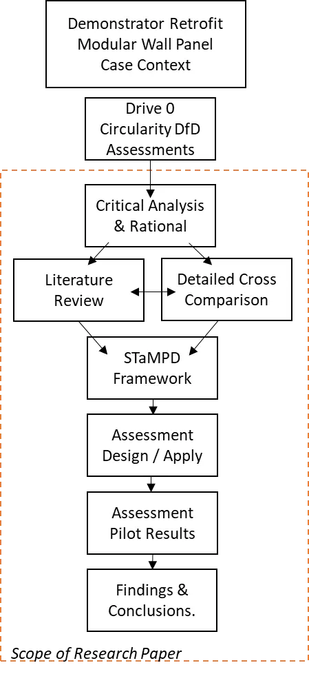
Figure 1. Research framework and scope in context of demonstrator and modular wall system case study. DfD: Design for Disassembly.
The principal question examined is, in contrast to the simplistic approach in Drive 0, can a more holistic and detail DfD assessment method be developed, with sub-questions including: How is DfD being assessed in literature and what are the principal indicators of performance? How can these be incorporated into a more holistic approach? How will a new proposed DfD method work in actual case practice? Can such a DfD assessment method influence design toward achieving advanced performance?
2. Research Methods
2.1 Research approach
This novel research presents the development and pilot application of a holistic DfD assessment framework and method, which arose from a critique of the simplified circularity, DfD assessments undertaken within the EU Horizon 2020 funded ‘Drive 0’ project[1], as applied in the Irish demonstration case. The research examined a range of questions, including what is DfD in principle and how can performance be assessed? What are the indicators of possible performance, and can differentials and advanced performance be determined by a more holistic approach and method, compared to Drive 0?
The research is based on a precursor, grounded case study[2] of the Irish Drive 0 project and the circularity, DfD assessment methods, which highlighted several issues and limitations and provided a rationale for consideration of an alternative approach[3]. The research examined the area of achieving and assessing advanced DfD as a core element of circularity performance via the development and pilot testing of a more holistic DfD assessment approach/method based on a broader range of indicators, using simple scoring metrics, applicable at different levels of hierarchy and facilitating benchmarking and system comparison. The research used a range of research methods based around a case study framework, including literature review comparison, analysis and syntheses (both contextual and specific to DfD), as a basis for the design and development of a novel DfD assessment framework, which was tested at the design stage in the case study modular wall system, with critical review of the results and methods. The desk-based assessment was validated against real physical disassembly auditing, which is the subject of a separate more detailed case study paper.
This research contributes to several identified circularity knowledge gaps, notably holistic, comprehensive assessment tools, based on broad indicators, which consider deconstruction and standardisation, are applied in case retrofit practice, and are related to modularity and retrofit[4-9].
2.2 Research methods
i) Design Research, Case Study, DfD Design
Case Study Research acts as an overarching framework for a mixed methods approach with design iteration being central to the development of the modular wall systems, along with the development of a DfD assessment method, its pilot testing and critical application, including physical auditing of DfD performance.
ii) Literature Review
In addition to a comprehensive contextual literature review on circularity and modularity knowledge gaps, a focused and detailed literature review was conducted on DfD to identify the key issues and indicators pertaining to DfD function, performance and possible assessment.
iii) DfD Assessment Conceptual Framework
A range of performance indicators were identified and harmonised/categorised within a conceptual framework for holistic DfD consideration—STaMPD.
iv) DfD Assessment Method Design
Based on the conceptual STaMPD framework, an assessment method was designed and developed using Excel, to facilitate the early design stage and holistic assessment based on a scoring method of key indicators and categories, structured hierarchically.
v) DfD Assessment Method Pilot Application
This method was then piloted by two researchers on two comparative wall façade retrofit approaches, conventional EWI versus the Drive 0 Modular Wall System design, providing insights on design performance and assessment methodology, including limitations.
vi) DfD Assessment Pilot Results
Results in the form of scoring data relative to indicators and categories were then critically analysed leading to a critical commentary discussion and findings, on the design development, utility, and need for further development of the method.
3. Literature Review
3.1 Context
The building and civil sector is the largest consumer of raw materials worldwide, using around 3 billion tons of raw materials annually[10], with buildings accounting for approximately 32% of total global energy consumption[11]. In response to this high energy and material resource consumption[12,13], the EU has introduced significant policy and legislative initiatives focused on sustainability[14] and energy efficiency of its buildings[15], aiming to steer the economy and construction sector toward circularity[16].
Ireland is also advancing decarbonisation and the adoption of circular economy principles, reflected in national policies such as the Irish Climate Action Plan[17], which sets out strategies to reduce greenhouse gas emissions across multiple sectors, including construction, with the Circular Economy Act[18] providing a legislative foundation for embedding circular practices into Ireland’s economy, thereby promoting resource efficiency and waste reduction. In parallel, the Irish Green Building Council supports the industry’s transition with a range of frameworks and roadmaps for sustainable, low-carbon, and circular practices[19,20].
3.2 Circularity
Circularity represents a paradigm shift from the conventional linear model of “extract, produce, dispose” to a regenerative system in which resources circulate continuously through the economy. This approach aims to minimise resource use and waste generation at a product’s end-of-life stage[21]. The concept builds on earlier frameworks such as Braungart and McDonough’s cradle-to-cradle philosophy[22], regenerative design[23], and Stahel’s closed-loop strategies and product-life factors[24,25]. Within the built environment, circularity is receiving increasing research attention[26,27]. However, there is no universally accepted definition, with multiple frameworks, criteria, and metrics proposed across the literature[28-30].
DfD is a central principle of circular construction and is widely regarded as critical to the circular processes as DfD facilitates recovery and reintegration of building materials and elements back into the supply chain[9,31-33]. Despite its relevance, both circularity and DfD remain under-researched, particularly in terms of comprehensive life-cycle assessment methodologies[4,12,34-37].
Several methodological gaps persist. There is a lack of integrated tools for assessing circularity in construction projects[8], as well as a need for early design stage tools[38] and reliable case-based verification frameworks[4,39,40]. The literature also highlights the need for more robust indicators and methods to quantify performance, benefits, and value[4,6,7,9].
Technological limitations further hinder adoption. These include advancing DfD to improve the reuse of deconstructed materials, enhancing the disassembly of existing structures, and promoting standardisation with fewer, more adaptable components[41]. The relationship between modular construction and circularity, particularly through off-site manufacturing, remains insufficiently explored, with practical case studies needed to address this gap[42,43]. Additionally, the development of circular typologies in building design faces barriers[44], and the retrofitting of existing structures within a circular framework is still significantly underexplored[9,37].
3.3 Modularity in construction and retrofitting
Modular construction is a contemporary approach involving the off-site fabrication of building elements in controlled factory environments. These prefabricated elements, or modules, are then transported to the construction site for final assembly, enabling a more streamlined and efficient building process[45]. Claimed advantages of modular construction include standardisation and simplicity, which allow for mass production, cost reduction, shortened construction timelines, and improved maintenance. Its modular nature also offers flexibility in design, adaptability to different functions, ease of disassembly, and the ability to customise through interchangeable components[46-49].
Across Europe, modular construction is increasingly applied to energy retrofits, supported by research, innovation, and demonstration projects. Annex 50 of the International Energy Agency evaluated demonstration projects using standardised, highly insulated prefabricated façades in apartment retrofits. Reported benefits included enhanced energy efficiency, improved occupant comfort, higher construction quality, cost-effectiveness, better use of space, and substantially reduced retrofit durations, all with minimal disruption to residents[50]. D’Oca et al.[51], in a review of 31 EU-funded deep energy retrofit projects, found that many employed prefabrication for façades or energy systems. For instance, the iNSPIRE project (2012-2016) developed timber-based modular façade systems integrating micro heat pumps and ductwork[52]. Similarly, the MORE-CONNECT project (2014-2016) delivered affordable modular retrofit solutions targeting Nearly Zero Energy Building standards. These included multifunctional prefabricated façades and roofs incorporating photovoltaic panels, ventilation systems, and shading devices, with installation times reduced from approximately two months to just five days[53].
Other pilot strategies include opaque, lightweight wood-based vertical panels[54], adaptable timber façades for different structural types[55], and insulated panels using textile-reinforced concrete with an EPS core[56]. Additional innovations include preassembled timber panels for retrofitting pitched roofs[57] and integrated renewable energy systems adaptable to diverse climates and building types[49,51]. Despite these advances, several challenges remain. Du et al. (2019)[49] identified technical issues such as modular design, fixing systems, and integration of renewables, as well as financial challenges linked to market penetration, business models, warranties, and servicing. Torres et al.[57] noted further technical obstacles, particularly integration into varied structures and irregular geometries.
Pope[58] identified systemic barriers to scaling modular retrofitting, including the need for coordinated multi-stakeholder supply chains, harmonised regulations, common protocols and data-sharing tools, and financing solutions for tenant-owner arrangements. Without sufficient market scale to reduce costs and stimulate investment and labour capacity, he stressed that government support will be essential to avoid stagnation. In their review of Horizon 2020-funded projects such as 4RinEU, P2ENDURE, Pro-GET-OnE, and MORE-CONNECT, D’Oca et al.[51] concluded that the most pressing barriers are not technical but stem from low awareness, knowledge gaps, and high upfront investment requirements.
4. Design Development
4.1 The case demonstrator
The Irish demonstrator retrofit targeted a significant 65% energy upgrade to two 1970’s social houses of masonry wall and timber roof construction, which had some previous retrofitting works undertaken. Figure 2 shows the Irish case dwellings photo of front elevation and cross section.

Figure 2. (LHS) Photos of existing case dwellings front elevation and cross section. Source LHS TUDublin; (RHS) Westmeath County Council[3]. LHS: left-hand side; RHS: right-hand side.
The principal innovation was to design and pilot a novel ‘2D’ modularised wall panel for wall over cladding and construction of a simple extension ‘3D pod’ based on circular and DfD principles. This was executed via the adaptation of an existing LGS structural wall system into a pre-fabricated ‘closed’ wall unit for over cladding application. Figure 3 shows the conventional LGS system and application as proposed retrofit over cladding.
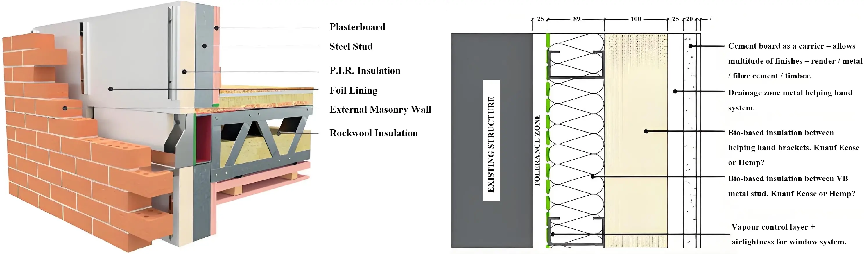
Figure 3. The LHS shows the conventional structural application of the Vision Built LGS system, while the RHS illustrates its integration into a modular biobased panel. Source LHS Vision Built, RHS Coady Architects. LGS: light gauge steel; LHS: left-hand side; RHS: right-hand side; VB: vapor barrier.
4.2 Emerging concept design
Concept designs were developed for both the overall energy retrofit, including architectural elevations for the modular plug and play wall over cladding and an extension to the front elevation as well as the proposed build-up of the modular panel itself, incorporating circularity—DfD aims and principles. The retrofit of the front elevation, to which the modular solution was limited due to budget issues, was to comprise the installation of four full story height/dwelling width 2D modular overclad finished wall panels, complete with integral windows and doors, along with a 3D extension ‘pod’ providing a porch-lobby, utility space.
The proposed modular wall panel was to be based on the 89 mm LGS stud framing with a biobased quilt insulation between, with membrane to rear along with 25 mm compressible insulation with neoprene seals at edges, to reduce or eliminate thermal looping to rear of panel, and with wood fibre board to front along with breather membrane, batten, cement board and render finish to U Value of 0.18-0.2 Wm2k. Figure 4 shows the concept images of the proposed panel and its application in 2D wall over-cladding to front elevation and in a 3D extension pod.

Figure 4. The LHS shows the architects’ 3D rendered model of the retrofitted front elevation with modular wall over-cladding and pod porch/lobby, while the RHS presents an early schematic of the modularised wall panel build-up incorporating biobased materials. RHS: right-hand side; LHS: left-hand side.
4.3 DfD in construction hierarchy
A key aspect of design development was how to integrate DfD, with the Irish researchers advocating a strong emphasis on DfD at all construction levels (wall panel, component and product/material), to retain environmental, resource and economic ‘value’ at all levels, critically enabling the modular panel to be uninstalled from the host wall in its entirety for re-application or further disassembly of components (wall—window/cill) or base products/materials across reuse to recycling R-stages. These principles were integrated into the design development of the proposed modular system and were a central component of the prototype mock-up design and DfD performance testing.
Figure 5 shows the circularity DfD concept for Irish modular system at three levels of hierarchy.
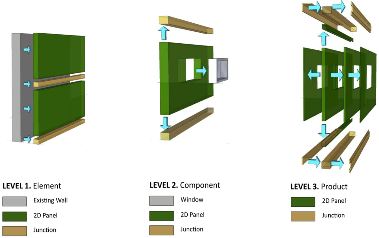
Figure 5. Schematic 3D of hierarchical levels for DfD and its assessment, for panel to host wall, key components and assembly of wall unit from products and materials[3]. DfD: Design for Disassembly.
4.4 Detail design
The modular wall panel system was designed to address structural integrity, thermal upgrade, disassembly potential, durability and aesthetics, while complying with relevant Irish and European standards. The system comprises a cold-formed LGS frame/panel, acting as a non-load-bearing wall over-cladding, fixed with adjustable brackets to a host masonry wall.
i) Design for Disassembly
Design workshops address key junction details and integrated DfD principles, leading to solutions supporting DfD at each construction level. Figure 6 illustrates the horizontal access junction, which uses an adjustable steel bracket to independently support each panel by gravity and restraint, thereby avoiding direct fixings through the panel into the host wall. A 150 mm panel head junction zone provides drop-on/lift-off capability and clearance for installation beneath roof projecting eaves. The first-floor window head-to-eaves dimension was critical for maintaining the alignment of horizontal studs in the upper panel. Vertical panel junctions are butt-jointed and sealed with a neoprene gasket and elastomeric mastic, accommodating differential movement while maintaining weather-tightness.
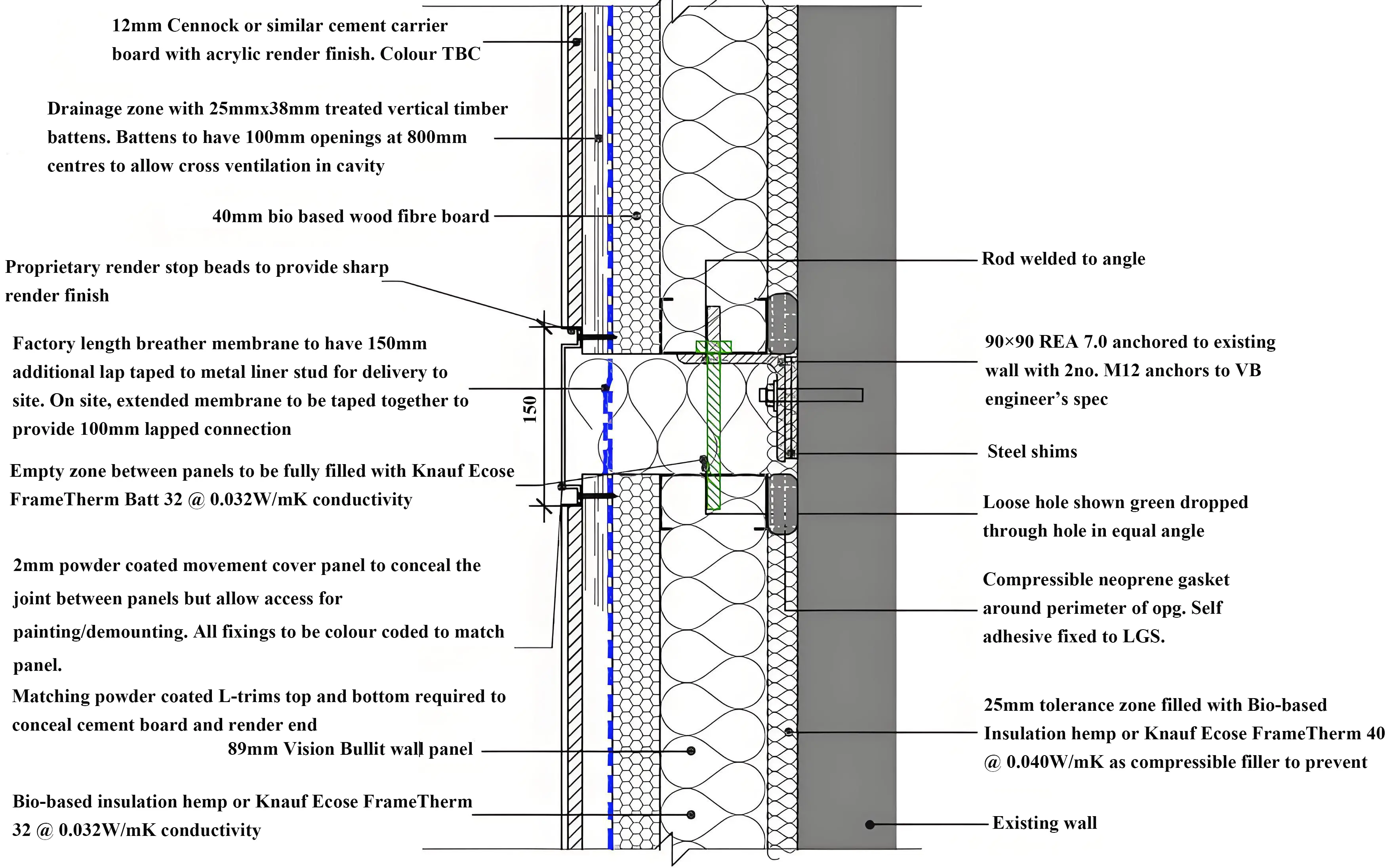
Figure 6. Original proposed horizontal panel to panel connection at floor level based on DfD strategy to enable independent installation (non stacking) and de-installation of panels in entirety for potential reuse as structural walls or for further disassembly. This proposal is based on a gravity fixing, with the panel base sitting on a bracket, (which is bolt fixed to host wall), and the panel restrained via a simple stud holding it in place, and the same bracket being used to restrain the head of the lower panel via a restraint bolt. All of this is accessible via a circa 150 mm access/lift on lift off access zone. Detail was revised during prototyping to provide bracket adjustability. DfD: Design for Disassembly.
ii) Structural Considerations
Although non-load bearing, panels were designed to carry self-weight and resist wind-induced forces, transferring the loads to existing masonry via the bracket and restraint system. Structural design followed the limit-state principles of the Eurocodes (0-6) and the Irish National Annexes[59], ensuring compliance with Part A of the Irish Building Regulations[60]. Wind actions were determined per Eurocode 1, with load combinations and safety factors from Eurocode 0. LGS frames and brackets were designed in accordance with Eurocode 3, considering the behaviour of cold-formed steel members and their joints. Steel components were protected per EN ISO 12944[61], appropriate to site exposure. The host masonry was assessed following Eurocode 6 and SR 325[62], ensuring adequate capacity for bracket anchoring. Figure 6 presents the initially proposed bracketry, facilitating a drop-on/lift-off demountable connection between the panel and the host wall. Fixings employed post-installed anchors, designed and installed per best-practice procedures[63]. Panel lifting points were designed and proof-tested according to EN 13155[64]. Steel elements were hot-dip galvanised to mitigate corrosion, and were tested and revised during the mock-up stage to facilitate greater movement and tolerance, uplift, and deflection performance. Although originally non-load-bearing, the LGS panels are derived from load-bearing wall typologies, allowing their potential reuse in secondary structural applications and thus supporting circularity cascading principles.
4.5 Prototype/mock-up design
A key requirement of the Drive 0 project was to pilot the proposed designs in a scale mockup prior to their full realisation in the case dwellings. This proved invaluable and highly informative to the design and provided an opportunity to undertake actual physical audit of the proposed DfD performance. To facilitate this process, and in parallel with detail design work, a comprehensive mock-up briefing plan and document was prepared, which defined the objectives of the mock-up, combining technical, aesthetic, and DfD performance auditing requirements. It also described the scope, the number of panels, junction types, data requirements (including specification and production drawings), design variation options (e.g., different finishes or brackets), and a detailed DfD audit plan specifying the stages, sequence of work, roles of research team, and coordination needs. Based on this briefing document/plan, a comprehensive mock-up design was developed, comprising three 2D wall overclad panels, two extension wall panels, and a small roof section. These components captured all the key panel and junction types anticipated in the actual case retrofit. The mock-up was to be installed on the external gable of the manufacturer’s factory wall and be remained in situ for several weeks/months for weathering exposure while the final retrofit design was completed. Figure 7 illustrates the mock-up’s 3D design images and panel types.

Figure 7. 3D schematic showing mock-up design, covering all panel and junction types required for the actual retrofit project. Source Vision Built. EXC: external wall construction; RFC: rain-screen façade cladding; FLC: floor construction.
5. STaMPD DfD Assessment Method
5.1 Drive 0 circularity DfD critique
The Irish wall panel solution was developed in the context of ongoing circularity and DfD assessments, based on a simplified method established within the Drive 0 project. This method not only had utility in aiding design development, but its application also provided a basis for a detailed critical review of circularity, DfD and assessment methods concerning technical aspects of the Irish case and more general aspects in relation to circularity and DfD assessment and realisation. The Drive 0 assessment approach concentrated on specific material factors, most notably embodied energy (EE) and carbon, and on key technical DfD aspects. The latter were derived from Alba concepts[65] and selected indicators from Durmisevic’s work[66]. These elements were applied at different stages of the project to support design development and benchmarking of modular wall panels for use in the demonstration cases. Circularity and DfD assessments were conducted at several critical phases throughout the Drive 0 project, reflecting a progressive enhancement in understanding and methodological adaptation over time. While EE and carbon were assessed at specific stages, DfD remained the central focus of the circularity evaluations.
Table 1 summarises the circularity–DfD assessments carried out during the Drive 0 project, illustrating that four of Durmisevic’s DfD indicators formed the consistent core of all evaluations. Material assessments, specifically the calculation of initial EE and embodied carbon based on data from the University of Bath’s Inventory of Carbon and Energy[67], were included in two of the four assessments. Hierarchical analysis, however, was generally not considered[3].
Table 1. An overview of the Drive 0 circularity–DfD assessments undertaken over the duration of the project, detailing four distinct stages of evaluation together with observations on hierarchical level, assessment focus, scope, selected indicators, data types employed, and general remarks[3].
| Summary of Drive 0 Circularity and DfD Assessments | |||||||
| No | Stage | Hieararchy Levels | Assessment | Scope | Indicators | Data Type | Comments |
| 1 | Initial benchmark on existing dwelling (Del 6.1) | Not applied, single level—product/materials | Circ/DfD | Technical Assembly | Durmisivec 4, (Type, Access, Independance, Edge) | Scoring Matrix | Non Integrated, three outputs—Score, EE EC, Mass. |
| Materials | Various | Mass, Embodied Energy/Carbon | ICE Database, Material Spec. | ||||
| Re-Stages | Retrofit elements | 7 levels of re-application | Comment | ||||
| 2 | First assessment of propsoed wall modules (Del 3.3, Task 3.3) | Not applied, single level—product/materials | Circ DfD Product/Material | Technical Assembly/Materiality | Durmisevic 4, (Type, Access, Independance, Edge), Materiality (Virgin, Renewable, Biobased) | Scoring Matrix | Non Integrated, Numerious outputs—two seperate benchmark scores, EE EC, various yes/no and qualitative answers. |
| Circ DfD Panel Junctions | Technical Assembly/Materiality | Durmisevic 4, (Type, Access, Independance, Edge), Materiality (Virgin, Renewable, Biobased) | Scoring Matrix | ||||
| Questionaires | Various | homogeneity, layering, prefabrication, number and complexity of parts, and standardisation, | Yes/No Anwers | ||||
| Materials | Materials | Embodied Energy/Carbon, | ICE Database | ||||
| 3 | Sample junction detail wall modules (Del 2.5, Task 2.6) | Not applied, single level—product/materials | Circ/DfD | Technical Assembly | Durmisevic 2, (Type, Access) | Scoring Matrix | Single score and graphic output |
| 4 | Final assessment of wall panels (Del 2.2, Task 2.3) | Partial application, three levels (element, material, maintenance) | Circ/DfD | Technical Assembly | Durmisevic 4, (Type, Access, Independance, Edge) only 2 at lower level | Scoring Matrix | Irish Adpated for full hierarchy level approach. Single score and graphic output |
| Materials | Various | Embodied Energy/Carbon, | ICE Database | ||||
| Re-Stages | Layers | 5 levels of re-application | Selection | ||||
DfD: Design for Disassembly; EE: embodied energy; EC: embodied carbon; ICE: inventory of carbon and energy.
The critique emphasised that, while the assessments proved useful in informing and guiding the design development of the modularised panels, they also revealed significant challenges and complexities inherent in the process. Specific critiques concerned the tension between methodological simplicity and real-world complexity, the restricted scope and number of indicators, issues of focus and weighting, the absence of hierarchical structuring, limitations in reapplication stages, and the lack of a unifying benchmark within the multi-criteria approach[3].
From these critiques, a rational for an alternative DfD assessment framework emerged. This would facilitate a more holistic approach with broader range of indicators based on common scoring metrics, allow sub and total score benchmarking, and be applicable at different levels of hierarchy.
5.2 Summary of key DfD papers
Complementing this critique of Drive 0 circularity assessments and method, a review of the key Drive 0-related literature on circularity–DfD principles, indicators and assessment methods, was conducted to identify and compare their scope, focus, range of indicators, associated categorisation, and scoring methods. The relevant papers comprised a mixture of design guidance/principles on disassembly and specific assessment methods showing a wide range of factors and indicators. All of them exhibited both commonalities and differences in relation to indicator types, range, definitions, scope, levels of categorisation, and, where applicable, scoring approaches.
i) Durmisevic.
The work of Durmisevic has influenced several other assessment methods, such as Alba Concepts, which served as the primary basis for the Drive 0 circularity assessment method, and relied on only four technical-physical indicators.
Durmisevic’s work presents an in-depth, sophisticated analysis and approach to DfD design and assessment, focusing exclusively on the physical—technical connection and relationships between elements. The approach comprises 17 indicators grouped in a tri-tiered categorisation under functional, technical and physical decomposition. As noted by the author, these include assembly system indicators, i.e., the relationships among parts, clustering, and sequence[68,69].
Key indicators identified and defined by Durmisevic are summarised as follows.
Functional separation and dependency are indicators that relate to how ‘independent’ elements or layers are with respect to distinct functionality, e.g., layers or elements with function separate from weathering function.
Systematisation—pertains to the relationship between elements, notably their clustering into autonomous subgroups according to function, life cycle and assembly.
Relational pattern—concerns the number and type of technical and functional relationships between parts or elements.
Base element—relates to design of key elements that serve as intermediaries between other elements in configuration.
Assembly/disassembly sequences—concern the order and sequence of assembly and connectivity.
Geometry and morphology—relates to the design and geometry of material or product edges in relation to ease of disconnection and extent of damage.
Connections—pertain to the type of connection and ease of decomposition and separation relevant to possible impacts on damage and re-use.
Life Cycle Coordination—concerns the co-ordination of elements relative to their life cycles within a construction and their disassembly sequence.
ii) Guy and Ciarimboli
The guidance papers by Guy and Ciarimboli have a broader range of indicators with a wider scope of categories, presenting over 25 factors in headings of ‘key principles’, ‘design strategies’ and ‘process’ indicators. The authors have related these to technical, material and process categories. Although several indicators correspond to some of Durmisevic’s physical and functional indicators, many specifically address material-related aspects such as toxicity, number of materials and durability. Importantly, they also discuss a range of data- and process-related indicators, including a section on process strategies that identify issues such as disassembly instructions, number of operations, knowledge and expertise, and safety. Additionally, broader factors such as costs and business models are discussed[70].
iii) Akinade et al.
Akinade et al. presents 17 factors or indicators grouped into three categories: i) material factors relating to technical aspects, ii) human factors, closely aligned with process, and iii) design factors, including macro level principles such as designing for offsite, modularity, open plan, layering, and standard grids more appropriate for building-level adaptability[71].
iv) van Vliet
van Vliet presents 25 indicators categorised into technical, process and financial ones, with the technical indicators drawing heavily from and closely aligned with that proposed by Durmisevic. The categories were expanded to include process-related aspects, including factors such as data, instruction, expertise, operations, safety, and finance factors of cost and time, which drew our interest. Notably, these two categories seem closely related to and possibly draw upon the perspectives of Guy and Ciarimboli, and Akinade[69].
v) ISO 20887
ISO 20887 outlines a range of adaptability and disassembly ‘principles’ applicable at five hierarchical levels—system, elements, component, sub-component and material. The principles, that are access, independence, reversibility, hazardous materials, re-application potential, simplicity, standardisation, safety and durability, relate to various categories in the preceding literature, notably process, materials and technical categories.
Overall, this review of highlighted Durmisevic as a foundational paper not only for Drive 0 but also for other papers notably van Vliet. Durmisevic focused on physical and technical connections while incorporating the concept of functional independence and several indicators related to the inter-relationship of parts, i.e., systems. In contrast, most other papers included broader categories ignored by Durmisevic, particularly material and process indicators including data, and ISO 20887 further included the concept of hierarchical consideration.
5.3 Detailed comparison of key DfD papers
A more detailed comparative analysis of these papers was conducted first by comparing scope and categories, and then by cross comparing individual indicators. Some indicators used different terms to describe the same concept, all toward harmonisation and collation of a holistic range of indicators and re-categorisation in a new DfD framework.
i) Scope and Categories
Figure 8 presents a conceptual summary of the papers in chronological order, beginning with Durmisevic[68] as a foundational paper, followed by Brad Guy et al.[70], Akinade et al.[71], Vliet[69], Drive 0[1] and ISO 20887[72]. It shows their principle categories, or where categories were absent, their equivalent groups, and the interrelationships with other papers.
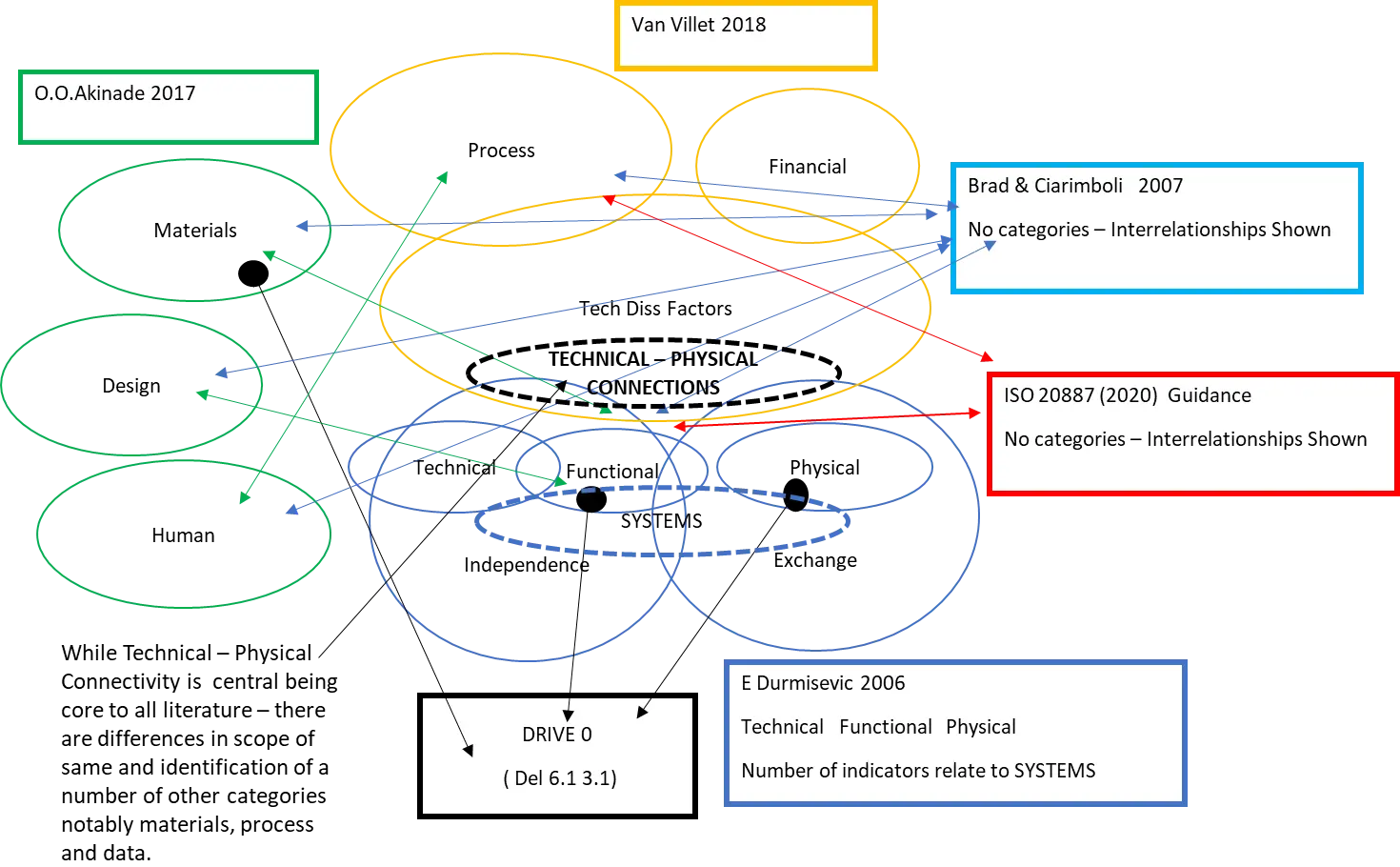
Figure 8. A conceptual schematic comparison of key categories and paper scope. Technical—physical’ factors are identified as central and core to all literature, however materials and process (including data) are also strongly represented across papers. Within Durmisevc’s categories system related indicators are identified by author as key and distinguishable. Most other papers include indicators pertaining to material and process, which includes data categories. The comparison helped clarify the core scope of indicators in the literature and key emerging categories of Technical/Systems, Materials and Process/Data.
Across the papers, a total of 14 original categories were identified. Some of them were distinct, while others were co-related to the categories in other papers but named differently, herein related to author re-categorisation. Durmisevic’s core categories include functional, technical and physical decomposition, with numerous indicators pertaining to systems. Guy and Ciarimboli do not define distinct categories, instead discussing factors under headings of key principles, detailed and process strategies; however, their indicators strongly relate to technical-functional, material and process categories. Akinade’s design category aligns closely with Durmisevic’s functional and physical categories, while the human category indicators clearly relate to process. It also presents a particular category of material indicators. Van Vliet’s ‘technical disassembly factors’ category, is strongly related to Durmisivec’s, technical categories and indicators, but include a process category and a minor financial category. ISO 20887 shows adaptability principles and design guidance, which also strongly correspond to technical, material and process categories, and notably advises a hierarchical approach[1,68,69,70-72].
From this comparison of literature, a clear scope and pattern of categorisation was identified as follows. Technical and physical aspects were consistently central across all papers; however, it was seen from the work of Durmisevic in particular that factors related to systems or relationships between parts were an important subset and could be identified as a distinct grouping or possible category. Material indicators were strongly represented in all papers except Durmisevic’s, and process indicators appeared in most papers, generally including data and information indicators even when these were not identified as a category. Categories related to broader finance, business and regulatory context were the least represented.
This review and cross-comparison revealed a clear scope and highlighted the emergence of key categories including Technical/Systems, Material and Process/Data. These categories formed the basis of a new DfD framework. A detailed comparative analysis and cross-comparison of the combined 47 indicators was subsequently conducted to enable harmonisation, reduction and integration into the new framework.
ii) Indicators Comparison/Harmonisation
A detailed cross-comparison of papers and their indicators, structured within this emerging re-categorisation, showed a diverse range of 47 indicators, encompassing factors, guidance and principles. These indicators were cross compared for definition, similarity and harmonisation. Among the studies, only Durmisevic proposed a defined scoring method, using a decimal scale from 0 to 1 for each indicator, which was applied by van Vliet for certain indicators.
The comparative analysis highlighted significant diversity across the literature in terms of types and range of factors and indicators, as well as how these can be categorised. However, some commonality and key observations emerged as follows.
Technical—physical indicators are central to all papers, forming the largest body of indicators. Nevertheless, distinct differences exist in their definitions, sub-categorisation and diverse factors pertaining to the same. Two key aspects from the work of Durmisevic are unique and considered of great importance: i) functional distinction and independence, which is arguably critical in relation to disassembly in terms of levels and building hierarchies, and ii) system-related aspects or the interrelationships between parts, such as sequence, order, clustering, number, and complexity. Although Durmisevic does not define the system aspects as a particular category, they can be considered a distinct grouping or category.
While Durmisevic’s work focuses in detail on the physical—technical aspect of connections, most of the other literature includes broader categories such as material and process/data as important categories. The identified material indicators, specific to disassembly rather than boarder environmental indicators such as mass, EE and carbon, include toxicity and durability, both of which could impede or enable disassembly. Process and data categories were also identified and seen as important with process more about ‘how to’ disassemble under the support of appropriate information and guidance. Process indicators included knowledge, skills, tools, sequence, complexity, and safety, all of which could clearly influence disassembly actions and potential. Data indicators included drawings, information, guidance associated with training and knowledge, which likewise can influence disassembly.
5.4 Conceptual framework
From the literature review and the re-categorisation and harmonisation of indicators, an alternative conceptual framing was developed. This framework distinguishes between categories and indicators pertaining to i) ‘what’ was being disassembled as the core, distinct to categories and indicators as to ii) ‘how’ they are disassembled, being secondary, and other iii) broader factors as tertiary. The core physical parameters relevant to ‘what’ is assembled/disassembled were derived from those identified in literature under three categories of ‘Technical’, ‘System’ and ‘Material’ aspects. In contrast, categories of ‘Process’ and ‘Data’ relate to ‘how’ the physical aspects are undertaken and are seen as secondary while exerting a strong influence on the core physical indicators. Finally, a range of indicators were identified as tertiary factors and considered overly broad and outside of designers’ influences, and as such beyond a reasonable scope and boundary of assessment. This formed the basis of the proposed STaMPD DfD conceptual framework represented in Figure 9.
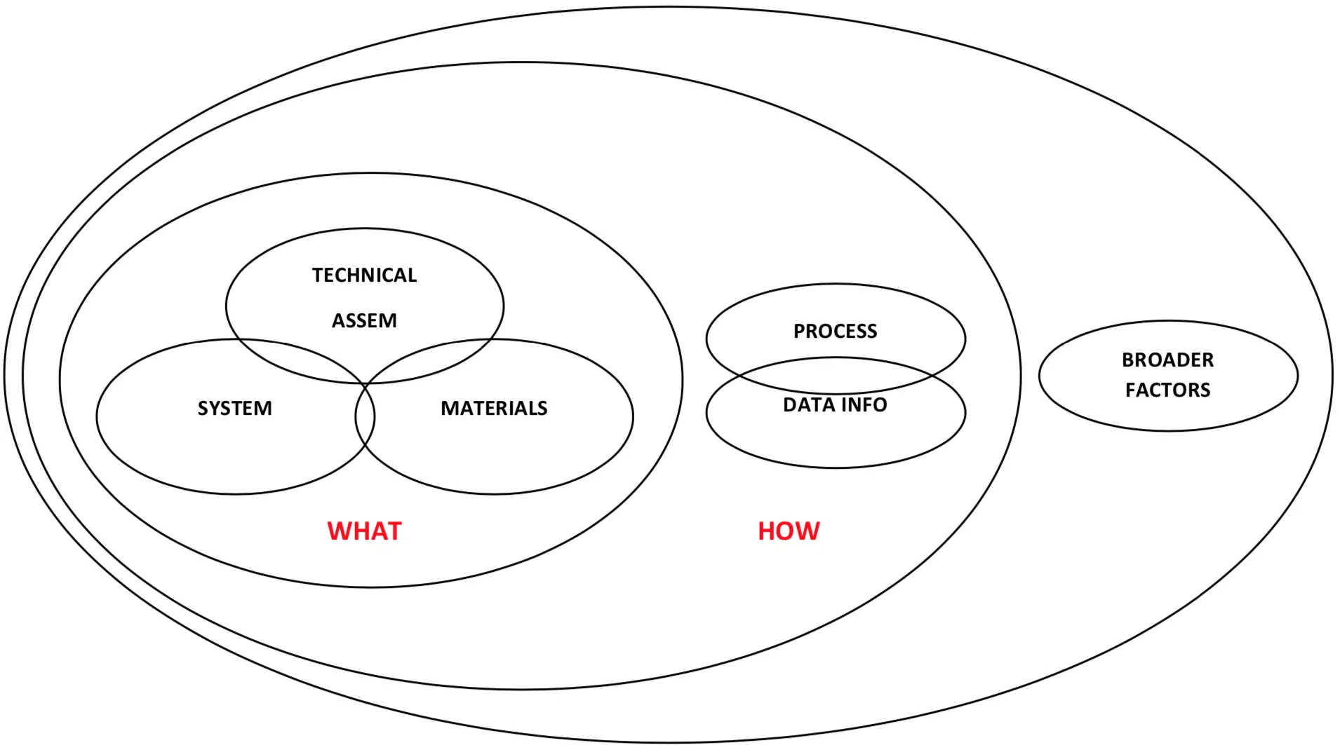
Figure 9. A conceptual diagram showing a proposed STaMPD framework for design for disassembly consideration and assessment from comparative literature review, showing core physical indicators pertaining to ‘what’ is being disassembled as central under categories of Technical, Systems and Materials, and related and influencing secondary Process and Data categories, relating to ’how’ things are being assembled/disassembled, with other categories outside of design influence being assigned to broader tertiary factors.
The central ‘what’ grouping of categories was defined as i) ‘Systems’—pertaining to the relationships between parts and their impacts on complexity sequence, and grouping, ii) ‘Technical’—pertaining to the physical connection between parts, elements and components, and iii) ‘Materials’—pertaining to material impacts on DfD, such as how materials can impede or aid DfD (e.g., toxicity).
The secondary ‘how’ grouping of categories was defined as iv) ‘Process’—pertaining to the process of how parts are assembled, disassembled, reassembled, and strongly related to v) ‘Data/Info’—pertaining to supportive information, guidance and directions on how to carry out the process.
The framework is intended to represent the principle categories of factors influencing DfD in a clear order of importance, with core physical aspects, Systems, Technical and Material, and secondary Process and Data aspects.
5.5 Harmonised indicators
Based on the comparative analysis of papers, a more detailed review of guidance and indicators was undertaken to collate, harmonise and refine the various factors and indicators for application within the proposed framework as follows.
‘Systems’—Category pertaining to the interrelationships between parts and elements that impact on complexity and can enable or inhibit disassembly. Influenced by Durmisevic, key indicators include standardisation of products, geometry, functional independence, relationships between parts, number of parts, connections and fixings.
‘Technical’—Category pertaining to the physical connection assembly, disassembly of parts, which are core to DfD. Informed by Durmisevic, key indicators include edge connections, connection types, accessibility and tolerance.
‘Material’—Category pertaining to material impacts on DfD, i.e., how material can impede DfD, with key indicators being toxicity, resilience, durability, number of materials and chemical composition.
‘Process’—Category pertaining to process of how parts are assembled, disassembled, reassembled, with key indicators being fabrication location, production, transport, assembly, tools, storage, safety, knowledge and skills, operational complexity and time.
‘Data/Info’—Category pertaining to supportive information, guidance and directions on how to undertake process, with key indicators being construction information, material information, disassembly instructions and safety information.
This represents 29 indicators (refined and harmonised from a total of 47 literature) in five key categories. This compares to the four technical DfD indicators in Drive 0, and is proposed to represent a more holistic and comprehensive consideration of DfD indicators for design integration and potential assessment benchmarking.
Using the STaMPD framework, scope, categories and range of indicators, an assessment method is devised, and pilot tested on the Irish case study comprising a modular circular wall system and a conventional EWI system.
5.6 Assessment method design
The rational for STaMPD is to develop a more holistic, design-stage DfD assessment method based on a comprehensive range of indicators, with assessment at different construction hierarchies. The method is intended to employ a simple scoring method, allowing different indicators and categories to be compared on the same scale and facilitating an overall total benchmark score. It is envisaged that the method can support early-stage design assessments, thus influencing design and specification. Where necessary, the approach allows for the application of professional knowledge and judgement, while reducing reliance on complex, diverse, and potentially unavailable metrics and data types/sources at certain design stages.
Based on this rational and criteria, a simple assessment method and scoring matrix was designed and developed using Excel, incorporating the following features:
i) Structure/Levels
The assessment matrix was structured across three levels, with products and materials as the base level, then going upward in hierarchy to the component level and element level. The five STaMPD categories and their corresponding indicators were assessed at each level.
ii) Categories and Indicators
The matrix incorporated and defined each of the five STaMPD categories and their harmonised indicators, with reference to descriptions in the source literature (noting interrelationships between indicators and categories).
iii) Scoring Criteria
A simple scoring criterion was established, based on a scale from 0 to 1. This allowed any variations of subdivisions per indicator, typically employing five scoring levels, with an optimal reference score of 1, facilitating cross-comparison of all indicators and categories on the same scale. The scoring was based on predefined qualitative performance descriptors. For example, connections were scored based on Durmesivec’s criterion. Other scoring categories were less well defined, and more reliant on assessor professional judgement, which could lead to subjectivity, e.g., process examples. Table 2 shows examples from the Technical and Process with Durmesivec’s scoring in yellow.
Table 2. Indicators, descriptors and scoring excerpted from the ‘STaMPD’ scoring method.
| TECH ASESSEMBLY | Descriptor (Simple) | Basis of Scoring | Score | |
| Product Edge Geometry | Type of connection at edges of elements parts or products (interpenetration, ease of separation, overlapping, abutment) | Open Linear | 1 | |
| Symmetrical overlapping | 0.8 | |||
| Overlapping on one side | 0.7 | |||
| Unsymmetrical overlapping | 0.4 | |||
| Insert on one sides | 0.2 | |||
| Insert on two sides | 0 | |||
| N/A | 0 | |||
| Type of connections | Connection typology in relation to ease of (ADR) | Dry Connection | Dry Connection | 1 |
| Click connection | ||||
| Velcro connection | ||||
| Magnetic connection | ||||
| Ferry connection | Connection with added elements | 0.75 | ||
| Corner connections | ||||
| Screw connection | ||||
| Bolt and nut connection | ||||
| Pin connections | Direct integral connection | 0.5 | ||
| Nail connection | ||||
| Kit connection | Soft chemical compound | 0.25 | ||
| Foam connection (PUR) | ||||
| Glue connection | Hard chemical connection | 0 | ||
| Pitch connection | ||||
| Weld connection | ||||
| Cement bond | ||||
| Chemical anchors | ||||
| Hard chemical connection | ||||
| N/A | 0 | |||
| Accessibility to Connections | Access to connections (type, quality, actions, impacts) | Freely accessible | 1 | |
| Accessibility with additional actions that do not cause damage | 0.75 | |||
| Accessibility with additional actions with reparable damage | 0.5 | |||
| Accessibility with additional actions with critical damage | 0.25 | |||
| Not accessible—irreparable damage to objects | 0 | |||
| N/A | 0 | |||
| Tolerance | Space, distance between parts to faciliate workability (ADR) | High | 1 | |
| Medium-High | 0.75 | |||
| Medium | 0.5 | |||
| Medium-Low | 0.25 | |||
| Low | 0 | |||
| N/A | 0 | |||
| PROCESS | Descriptor (Simple) | Basis of Scoring | Score | |
| Fabrication location types | Controlled Environment (factory, workshop) V Open—Site | High | 1 | |
| Medium-High | 0.75 | |||
| Medium | 0.5 | |||
| Medium-Low | 0.25 | |||
| Low | 0 | |||
| N/A | 0 | |||
| Production Plant, Machinery | The different types of plant and machines used at production stage, (number, specialism, complexity etc,) | High | 1 | |
| Medium-High | 0.75 | |||
| Medium | 0.5 | |||
| Medium-Low | 0.25 | |||
| Low | 0 | |||
| N/A | 0 | |||
| Transportability (Plant to Site) | Easiness to transport from plant to site | High | 1 | |
| Medium-High | 0.75 | |||
| Medium | 0.5 | |||
| Medium-Low | 0.25 | |||
| Low | 0 | |||
| N/A | 0 | |||
| Assembly Handling, Lifting (factory and site) | The process of assembly lifting moving handlings etc. (ease, quality, simplicity etc) | High | 1 | |
| Medium-High | 0.75 | |||
| Medium | 0.5 | |||
| Medium-Low | 0.25 | |||
| Low | 0 | |||
| N/A | 0 | |||
| Tools hand and powered tools (factory and site) | The different types of tools hand and powered tools used at production and site stage, (number, specialism, complexity etc,) | High | 1 | |
| Medium-High | 0.75 | |||
| Medium | 0.5 | |||
| Medium-Low | 0.25 | |||
| Low | 0 | |||
| N/A | 0 | |||
| Storage (plant-transport-site) | Quality of space provided to storage in dry and save conditions during all process | High | 1 | |
| Medium-High | 0.75 | |||
| Medium | 0.5 | |||
| Medium-Low | 0.25 | |||
| Low | 0 | |||
| N/A | 0 | |||
| Safety Practice | Safety of workers is guarantee easily during all process | High | 1 | |
| Medium-High | 0.75 | |||
| Medium | 0.5 | |||
| Medium-Low | 0.25 | |||
| Low | 0 | |||
| N/A | 0 | |||
| Expertise Knowledge Skill | Workers have theoretical instructions and previous experience | High | 1 | |
| Medium-High | 0.75 | |||
| Medium | 0.5 | |||
| Medium-Low | 0.25 | |||
| Low | 0 | |||
| N/A | 0 | |||
| Operation (Complexity, No, Sequence/Order) | Sequence, number of operations, complexity | High | 1 | |
| Medium-High | 0.75 | |||
| Medium | 0.5 | |||
| Medium-Low | 0.25 | |||
| Low | 0 | |||
| N/A | 0 | |||
| Time | The type required on site to installed a element, component or product. | High | 1 | |
| Medium-High | 0.75 | |||
| Medium | 0.5 | |||
| Medium-Low | 0.25 | |||
| Low | 0 | |||
| N/A | 0 | |||
ADR: assembly-disassembly-reassembly; PUR: polyurethane; N/A: Not Applicable.
iv) Proportional Factor (Volume)
A factor was included to account for the proportion of a particular element or material by volume within the construction at a particular hierarchical level, ensuring that results were proportional to volume of materials, products and components within the overall wall element. This required a dedicated sheet to calculate volumes for all key materials, components and elements at each level. Two options for assessment basis were provided: the exact design and an average representation. The latter was chosen based on a typical sample panel from the mock-up, as representative of the average panel.
v) Hierarchical Assessment/Weighting
A calculation sheet was set up for each construction hierarchy level, incorporating all categories, indicators, descriptions, scoring, reference scores, factor scores and total scores. It included potential for weighting of specific categories or indicators if deemed necessary.
vi) Results Collation and Graphics
A results page collated all scores per indicator, category, per level and total, and presented them using a range of tabular and graphical formats.
Figure 10 presents a schematic summary of the STaMPD method.
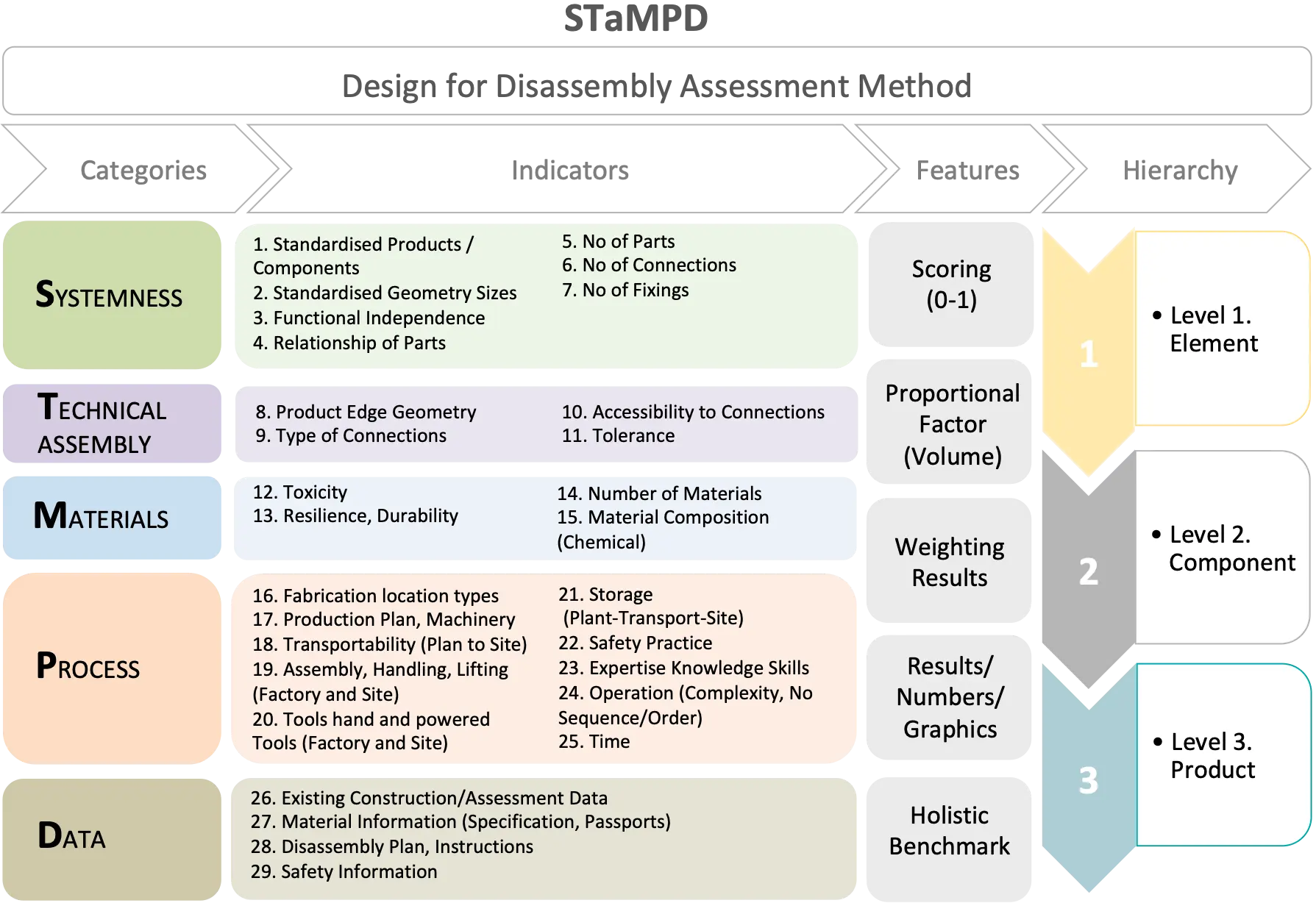
Figure 10. Overall scope and structure of STaMPD method comprising main categories, Systems, Technical, Materials, Process and Data, 29 indicators, key features of the method and hierarchical levels.
6. DfD Assessment Method Pilot/Results
6.1 Assessment process
The matrix assessment tool was piloted by two researchers (A—principle investigator and B—research assistant), during the design stage development of the Irish modular wall system, notably during the design of the mock-up (with researcher A completing the assessment after the mock-up and researcher B doing the same beforehand). As such, this was a desk-based mid-stage design assessment prior to the final detailed design and fabrication. The pilot assessment was undertaken on both the modular circular wall panel and a conventional EWI system for comparative purposes. Key aspects of the assessment process were described as follows.
i) Professional Knowledge/Experience
The completion of the assessment required professional knowledge and design experience, both in general design and construction principles and specifically in relation to the STaMPD pilot assessment method. Familiarity with material, technical details, manufacturing and construction assembly was necessary not only to understand and apply the conceptual framework, but also to make value judgements in scoring, especially where data was limited.
ii) Data and Information
Given the nature and stage of the pilot assessment as a desk-based study at the mid design stage, a range of design information was available, such as draft detail drawings of the panels at the mock-up stage, some material specifications, data sheets and generic product data. This information was supplemented by knowledge gained through participation in design workshops and project meetings, as well as conventional manufacturer drawings, details and specifications for the comparative EWI system.
Data related to the process category was very limited at the design stage, requiring professional knowledge and experience to make informed assessments. Similarly, data source for indicators such as safety and disassembly planning, were also limited, requiring professional judgement.
iii) Scoring
The scoring was conducted by both researchers separately to highlight possible differences in professional opinion and judgement regarding the interpretation of the method, categories, indicators and its application in construction hierarchy, resulting in possible scoring variations. Although good construction data were available in the form of drawings, details and some material specifications, professional judgement was still required where criterion descriptors were weak, or where data was limited and generic data or professional judgement and experience were utilised to translate this into specific indicators and scoring, with risk of subjectivity. Table 3 presents a comparison of scoring for Technical and Process by the two assessors.
Table 3. Different scoring comparisons for Technical and Process by the two pilot assessors, excerpted from the “STaMPD” scoring method.
| TECH ASESSEMBLY | Total Score Indicator | Optimal Score Indicator | Total Score Category % |
| Product Edge Geometry | 0.9 | 1 | |
| Type of connections | 0.7 | 1 | |
| Accessibility to Connections | 0.7 | 1 | |
| Tolerance | 0.9 | 1 | |
| TOTAL TECH ASESSEMBLY | 3.3 | 4 | 82.53 |
| TECH ASESSEMBLY | Total Score Indicator | Optimal Score Indicator | Total Score Category % |
| Product Edge Geometry | 1.0 | 1 | |
| Type of connections | 1.0 | 1 | |
| Accessibility to Connections | 0.7 | 1 | |
| Tolerance | 0.2 | 1 | |
| TOTAL TECH ASESSEMBLY | 2.9 | 4 | 73.06 |
| PROCESS | Total Score Indicator | Optimal Score Indicator | Total Score Category % |
| Fabrication location types | 0.9 | 1 | |
| Production Plant, Machinery | 0.5 | 1 | |
| Transportability (Plant to Site) | 0.8 | 1 | |
| Assembly Handling, Lifting (factory and site) | 0.3 | 1 | |
| Tools hand and powered tools (factory and site) | 1.0 | 1 | |
| Storage (plant-transport-site) | 0.8 | 1 | |
| Safety Practice | 1.0 | 1 | |
| Expertise Knowledge Skill | 0.7 | 1 | |
| Operation (Complexity, No, Sequence/Order) | 0.7 | 1 | |
| Time | 1.0 | 1 | |
| TOTAL PROCESS | 7.6 | 10 | 76.067 |
| PROCESS | Total Score Indicator | Optimal Score Indicator | Total Score Category % |
| Fabrication location types | 0.9 | 1 | |
| Production Plant, Machinery | 1.0 | 1 | |
| Transportability (Plant to Site) | 0.6 | 1 | |
| Assembly Handling, Lifting (factory and site) | 0.4 | 1 | |
| Tools hand and powered tools (factory and site) | 1.0 | 1 | |
| Storage (plant-transport-site) | 0.4 | 1 | |
| Saftety Practice | 0.0 | 1 | |
| Expertise Knoweldge Skill | 0.0 | 1 | |
| Operation (Complexity, No, Sequence/Order) | 0.6 | 1 | |
| Time | 1.0 | 1 | |
| TOTAL PROCESS | 5.6 | 10 | 56.385 |
Material indicators were mainly scored at material level but additional materiality indicators related to new materials at junctions at various levels were scored at those levels.
iv) Time and Detail
The timeframe required to undertake the assessment was significant, approximately three to five days, due to it being the first application on two distinct systems and the resulting details of the method, with 5 categories and 29 indicators across three levels, and the extent of scoring required especially at material level, with 58 score inputs and decisions required at the element and component levels and with six subcomponents at the material level requiring 179 scoring inputs, which was considered excessive.
v) Weightings
Material volumes in the construction were weighted in the scoring by a representative factor, as noted above, calculated for each material and level.
Two weighting strategies were implemented to represent weighting or focus on specific aspects such as i) levels—weighting levels higher in the hierarchy and ii) categories—weighting categories considered more critical, primarily the physical, technical, and systems categories, both using proportional distribution and simple factors.
6.2 Issues emerging during assessment
Researchers noted that scoring required careful attention on the hierarchical level being assessed and to the specific elements, components or product connections under consideration, with a natural tendency to default toward base-material level.
Given the stage of assessment there were some limits in data available and best professional judgement and or generic data had to be used, notably in relation to process and data categories. Researchers also conducted assessments at different stages, with researcher A completing the assessment after the mock-up, which may have influenced scoring differences.
Differences in scoring consistency were also observed between the modular system and EWI system. Both researchers collaborated and shared perspectives on the make-up of the modular system, but have different perspectives at element level for the EWI system.
There were also some minor potential errors on high or low score relative to something having a high or low value. For instance, a high number of fixings should be scored low rather than high.
On reflection, the relevance of all categories and indicators at certain levels, notably the material level, was discussed. In this context, the time frame for assessment was considered excessive for material level.
6.3 Pilot results
6.3.1 Average results: modular versus EWI systems
Unweighted average results from both researchers were examined and compared, showing a significant difference in DfD performance between the modular panel and the EWI system, and differences in each system at different hierarchical levels, notably in the EWI system.
The total score for the modular system is 74.6 out of 100, compared to 48.7 for the EWI system, with level-by-level comparison provided in Table 4. Figure 11, Figure 12 and Figure 13 present a detailed breakdown of these total results, and criterion scoring method in Section 5.6 and Section 6.1.

Figure 11. The unweighted average indicator scoring comparison for the modular system highlighting significant differences in scoring/potential performance between same across all levels.

Figure 12. The unweighted average indicator scoring comparison for EWI highlighting significant differences in scoring/potential performance between same across all levels. EWI: External Wall Insulation System.

Figure 13. Comparison radar charts for 2D modular system and EWI, top-unweighted average, mid-weighted categories, lower-category and levels weightings.
Table 4. Unweighted average results between 2D Modular and EWI.
| Level 1 | Level 2 | Level 3 | Total Avg. | |
| Modular | 73 | 74.5 | 77 | 74.6 |
| EWI | 46 | 53 | 46 | 48.7 |
EWI: External Wall Insulation System.
The EWI system performs consistently worse across all hierarchical levels.
i) Category Results
Figure 14 presents a graphic radar chart comparison of the average category results for both construction systems, clearly showing superior DfD performance for the modular systems, notably in the core physical categories—system, technical and material categories—across all levels, except for the Level 2 technical category. This aligns with the design intent of the modular system to achieve DfD at all hierarchical levels, whereas the EWI system can not be disassembled.
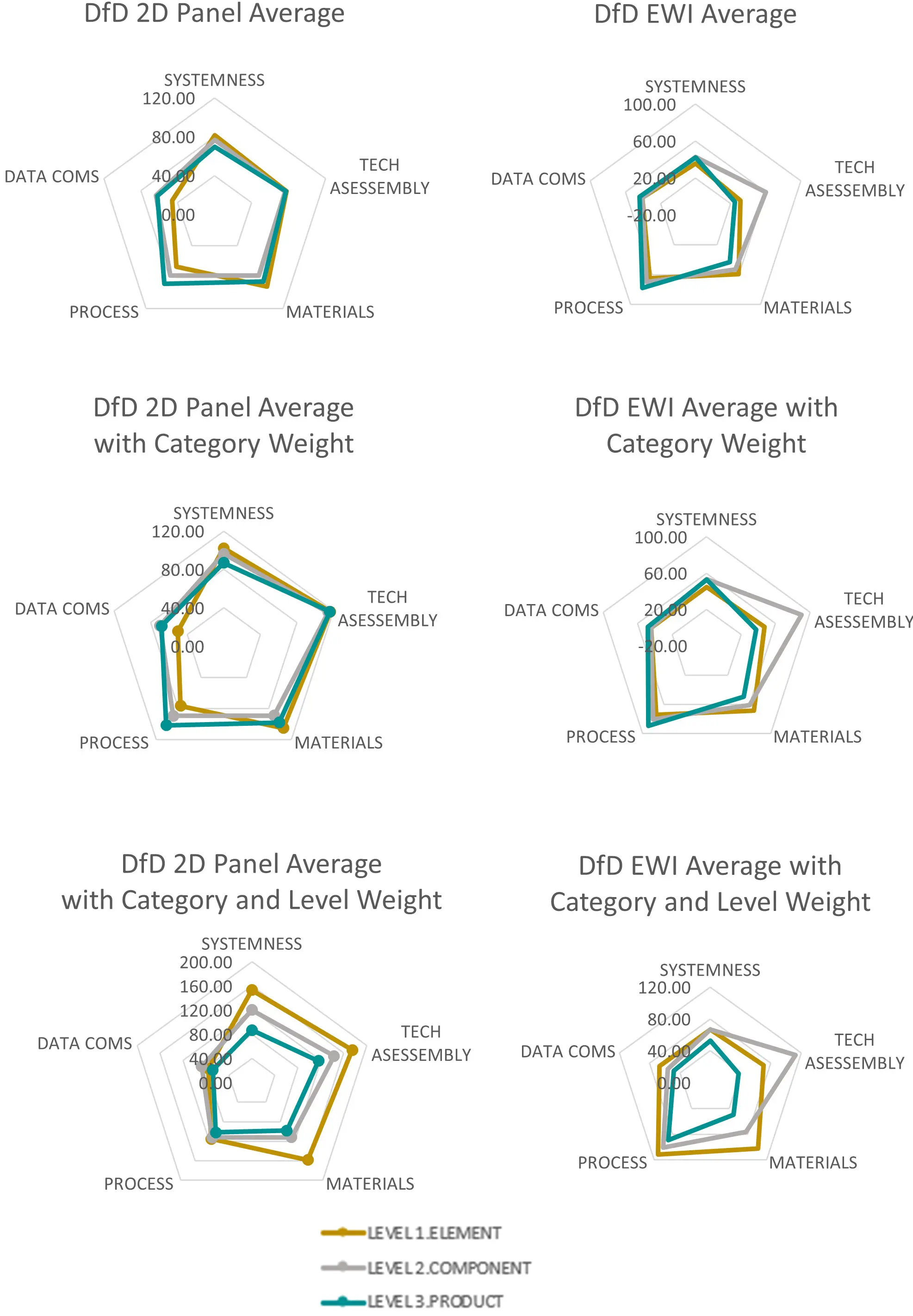
Figure 14. Average (unweighted) results comparison of STaMPD DfD assessment for 2D modular system and EWI system main categories, systems, technical, material, process and data, showing significantly superior DfD design performance for 2D modular system at all levels and notably for the core physical categories systems, technical and material. DfD: Design for Disassembly; EWI: External Wall Insulation System.
As shown, the modular system exhibits evenly distributed and higher performance scoring across all levels with advanced physical DfD at each level. However, the EWI system not only scores lower but shows variation across levels, particularly in material and technical categories, highlighting that DfD performances can differ in each hierarchy.
ii) Indicator Results
Figure 11 and Figure 12 present the average indicator scoring for both the modular and EWI system, highlighting substantial potential performance differences in the core physical categories, technical and material indicators, and to some degree, in process and data.
The EWI systems category scored well for standardisation, but poorly in other indicators. Specifically, in the EWI technical category, accessibility and connection score very low, with levels 1 and 3 performing markedly worse than the modular system. EWI Material category indicators score somewhat better but still inferior to the modular system, as do process and data.
6.3.2 Researcher results comparison
Comparison of researcher results indicate that some differences relate to several factors, notably the timing of scoring (researcher A scores pre- and post-mock-up of panels, whereas researcher B scores pre-mock-up only, resulting in differences in data and information). Other factors include variations in interpretation of indicators and application of scoring, as well as key differences in perspectives on the nature of EWI, notably at the element level. These are likely due to limited collaboration on the system, in contrast to the collaborative design and strategy agreement for the modular wall panel.
i) 2D Modular Panel—Scoring Differences,
There was generally good co-relation in scoring between researchers for the modular panel, notably for systems and technical categories, followed by the material category. However, greater variations were observed in process and data categories. The latter was attributed to the differences in researchers’ knowledge at the given stage and the limited data availability for those categories.
At Level 1 ‘element level’, there was a 12% difference in scoring due to minor assessor scoring differences between certain systems and technical indicators pertaining to the junction rather than the panel. Slight variations also occurred in the scoring of standardisation, the number and type of connections, and tolerance. There were also some minor differences in scoring of material durability and resilience, with overall scoring for data very similar but different for material information and safety/disassembly planning. The most significant difference was in process category, representing a 20% difference, because researcher B did not score certain indicators due to insufficient information.
At Level 2 ‘component level’, there was a larger 20% difference with only minor differences in scoring of systems and technical indicators as per Level 1 junctions and tolerance. However, material indicators exhibited significant variation (31.5%) in durability and number of materials. As at Level 1, substantial differences were observed in process indicators (25%), while data showed even greater difference (27%), partly because researcher B non-scoring certain indicators due to lack of data, whereas researcher A applied professional judgement and knowledge.
The scoring results at Level 3 were around 11.7%, with only minor differences for certain systems indicators and, as noted above, some differences in process and data categories due to strategic differences in approach to non-scoring or use of judgement for certain indicators.
Overall, minor differences existed in specific indicators across certain System, Technical and Material indicators. The main difference arose from differences in scoring or non-scoring of Process and Data indicators, due to variations in information and in professional opinion and judgement.
ii) EWI System—Scoring Differences
There were more pronounced differences in scoring between researchers on the EWI system, mainly due to non-collaboration in system design, in contrast to the modular system, and also due to significant differences in strategic perspectives on the nature of the EWI system at wall element level, with researcher B seeing it as a group of components and researcher A as a complete entity wrapping the house wall.
Compared to the 2D modular panel scoring, there were larger differences at Level 1 (30%) within the system (35%) and technical (50%) categories, notably in relation to standardisation, number of parts and connections, which were attributed to divergent perspectives on what constitutes the element at this level. There were minor differences in material-related toxicity indicators but more pronounced differences in indicators for process (25%) and data, notably machinery, operations and data.
At component Level 2, the overall difference was comparatively low (13%), with the pattern matching the 2D modular panel scoring, with minimal differences in systems, technical and material category indicators but notable differences in scoring of process (35%) and data (19%) indicators, such as operations, machinery, material information, safety, and disassembly planning.
At Level 3 product/material level, the overall difference is 20%, with the primary differences being chemical composition and number of materials (50%) under material category, and sequence and number of operations under process (29%) and safety planning under data.
Overall, the main differences in this assessment arose from a strategically different view and definition of the element at Level 3 with ongoing differences in interpretation of process and data indicators in part due to differences in stage of assessment.
The comparison of researcher scoring and basis thereof critically highlighted limitations in method due to subjectivity which would need to be reduced for wider application and benchmarking.
6.3.3 Weighting studies
In addition to the reapportionment of the main scoring by material volume factors, a separate series of weighting studies was conducted to examine the impacts of placing focus or weighting on particular categories and levels. With regard to categories, it could be argued that the physical categories are more critical, notably technical and systems. Accordingly, weightings were devised to explore the same. Regarding hierarchical levels, there is a strong argument that elements higher in the hierarchy should be valued more as they retain higher value—both economic and environmental, as the reapplication of elements at this level means extensive reuse and application, lower damage, waste and energy intensity compared to remanufacturing or recycling.
The same weighting studies were therefore undertaken for categories, levels, and combined categories and levels using both reproportioning and factors. The reproportion of scores seemed to distort results negatively, while the factor weighting was considered simpler to interpret and is presented here.
i) Factors
Category weightings were applied to place more emphasis on the physical categories by application of the following factors:
Technical 1.5
Systems 1.25
Material 1.15
Process 1.15
Data 1.1
Levels were also weighted (combined with category weighting) with the following factors:
Level 1 Element 1.5
Level 2 Components 1.25
Level 3 Product/Material 1
ii) Weighting Results
The results of this study show the comparison of unweighted and category weighting and combined category/levels weighting on average scores for both the modular 2D system and the EWI system from left to right, increased scores for physical indicators, notably technical and systems, and greater variation across hierarchical levels, especially when levels are weighted. Figure 13 illustrates the results of the weighting studies.
The weighting study reveals the potential of the method to allocate weight in an assessment framework to particular levels or categories, typically supporting hierarchy and value retention. This level-weighting exercise clearly highlights the superior performance of the modular system at all levels in hierarchy, notably within the physical categories.
6.4 DfD audit—STaMPD validation
6.4.1 Preliminary comparisons
After the design-stage piloting of the STaMPD method, a comprehensive physical audit of DfD performance was conducted during realisation of the prototype mock-up, (See Section 4 and Figure 7 for details of the prototype). This audit facilitated a comparison between actual DfD performance and the pilot design-stage STaMPD assessment method.
The DfD audit, including a detailed assessment of the assembly, installation, de-installation, and disassembly/reassembly of products, components and wall elements at different levels of hierarchy, broadly indicated minimal impact and damage to the core panel elements and parts during the de-installation and disassembly process, with predominantly tertiary/jointing materials being the most impacted.
De-installation of the panels from the host wall provided DfD insights at Level 1, with panels successfully removed intact, confirming DfD feasibility at element level as follows.
System/Technical: Horizontal joints and bracket fixings performed well with some unavoidable impact on the membrane and taping. However, soft-bonded vertical seals hindered independent panel removal. Material: Membranes and rubber seals were damaged beyond reuse, while the core panel materials remained intact. Process/Data: Disassembly was efficient using hand tools and forklifts, aided by prior assembly knowledge and simple documentation with mark ups.
Full disassembly at Level 2 Component and Level 3 Materials/Products: Two panels were disassembled: one at component level (Level 2) and one at material/product level (Level 3). Level 2: Window–cill units showed poor independence, requiring some destructive removal at cill, highlighting conventional detailing unsuited to DfD. Level 3: Full disassembly confirmed high recoverability, with all major materials separated with minimal damage. Cement board and render bonding limited reuse potential, while weathering caused minor degradation of gasket and membrane.
Overall, the core construction elements and products were able to be disassembled and reassembled back to functional modular panels, which were subsequently reinstalled as thermally insulating over-cladding panels onto the external host wall. This was achieved with minor material impacts, while accommodating revised design features and finishes and allowing scope for further design improvements. Preliminary observations from this physical DfD audit broadly aligned with the STaMPD design stage assessment for Systems, Technical and Materials (despite lower-than-envisaged DfD performance for some jointing materials), as well as Process. However, actual DfD performance for Data exceeded design stage expectations, as operatives had access to detailed technical drawings, which were supplemented with markups and notes on both drawings and physical parts to facilitate disassembly/reassembly.
6.4.2 Revised assessment
A revised STaMPD assessment was also undertaken by researcher A to re-examine the design stage assessment with post-prototype information/assessment. This incorporated knowledge and insights gained during the physical DfD audit, including some minor design changes, notably the removal of rear-panel neoprene gaskets and the switching to a dry cement board finish. The results indicated only minor overall differences, with total percentage score variation of less than 2%, comprising the main difference at material/product level of 4%, followed by component 1% and element 0.25%. The principle differences are noted for each category as follows.
i) Systems 3% Difference
The DfD audit complimented and supported the original design-stage STaMPD high result scores for indicators under Systems category, with clear differences in assessment across levels. Level 3 was the weakest due to the relatively high number of fixings, connections and parts. This was clearly demonstrated and reported in the DfD audit at Level 3 stages in particular and identified as an area for design review.
ii) Technical: 4% Difference
Technical Assembly scored highly across all three levels in the STaMPD design stage assessment; however, the actual number of fixings and their damage, redundancy and replacement only became evident in the DfD audit where they were identified as a key issue for improvement. The poorly designed cill-to-cladding interface, requiring cutting of the cladding to install and deinstall, was also reflected in the DfD audit assessment.
iii) Material: 4% Difference
Material composition scored well in the original design stage STaMPD assessment, with no toxic, hazardous, or chemically conflicting materials, and with high reapplication or recycle potential. However, the DfD audit highlighted specific damage and impacts, mainly affecting jointing materials, enabling a more detailed revised STaMPD assessment and identification of potential design improvements.
iv) Process: 3% Difference
Process indicators scored relatively well at design stage, performing the strongest at Level 3 product, medium at Level 2 component and the poorest at Level 1 element level, which was confirmed and evident in the DfD audit and assessment. Key differences were in slightly slower than those in anticipated installation and site complications.
v) Data: 5% Difference
Data indicators were the poorest scoring in the original STaMPD assessment and were reported in the DfD audit. However, somewhat better than envisaged data scores were applied in the reassessment, with operatives using marked-up assembly drawings for disassembly and drawing from experience in assembly and disassembly, including marking up components, products and materials specifically to guide reassembly.
Figure 15 shows a comparison between design stage STaMPD assessment and post DfD Audit STaMPD assessment results.
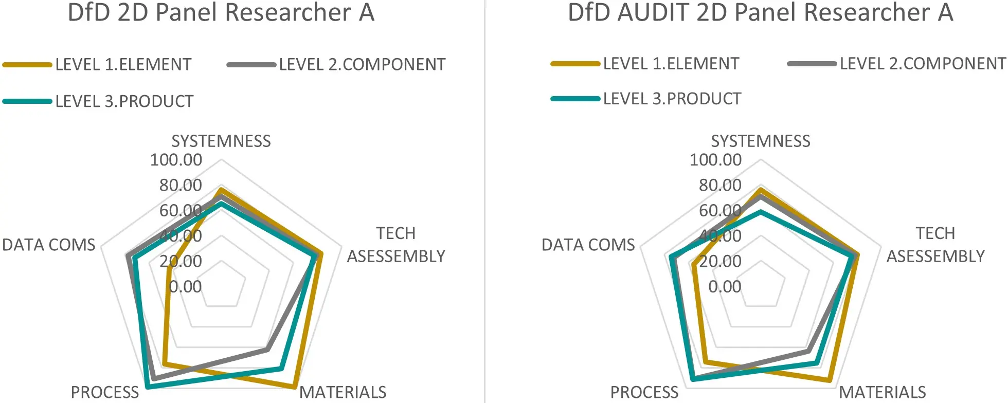
Figure 15. Comparing (LHS) design stage STaMPD assessment results, with (RHS) post physical DfD exercise-audit revised STaMPD assessment, showing only minor variations. LHS: left-hand side; RHS: right-hand side; DfD: Design for Disassembly.
These comparative results indicate that the DfD design intent was broadly realised in the prototype, albeit with scope for improvement. They also provide some validation support for the STaMPD method as both a useful design framework/guidance and a more holistic assessment method that broadly reflected DfD performance and achievable outcomes, despite its methodological limitations, notably the scope of data input and time intensity.
7. Critical Commentary
7.1 Overview
The research demonstrated the design and piloting of a more holistic and comprehensive DfD assessment method, based on objectives that included: a comprehensive range of indicators for application at different levels of construction hierarchy, use of a simple scoring method to allow cross-comparison of a diverse set of qualitative indicators and categories on the same scale, and the facilitation of a single benchmark/results.
The research critically appraised how DfD was assessed in the literature, deriving from literature—the scope, focus, principal indicators and categories for a holistic novel method. These were harmonised into 29 indicators across revised categories, reflecting both physical aspects (e.g., technical connectivity, material properties, and system design), and process-related aspects (e.g., data, information management, and knowledge requirements). This method aligned with literature highlighting the need to consider both dimensions[4,6,7,31-33,71].
Overall, the pilot study results showed that, in contrast to the highly simplified Drive 0 approach[1], a more holistic and detailed DfD assessment method was feasible and applicable in practice. High-level outcomes revealed significant differences in DfD performance between the modular system and the EWI system, both overall and across specific levels, categories and indicators with the modular system clearly outperforming the EWI system. The results also indicated clear differences in performance not only across categories but importantly across hierarchical levels, notably for the EWI system when compared to the modular panel. These findings are consistent with prior literature on the possible benefits of modular construction for circularity, particularly its potential to support disassembly, material reuse, and advanced circular design[42,46,49,51].
There were minor to medium variations in scoring between researchers partly due to different assessment stages, different professional judgments, and different understanding of the EWI system at element level in particular This highlighted the potential for subjectivity and a limitation of the pilot method, reflecting tensions in building design stage tools concerning data availability and professional knowledge and judgement, which should be a focus of a proposed revised method[4,5,71]. Weighting was shown to be useful to give greater value to indicators, categories or levels as required, and in this case, it further emphasised the superior performance of the circular modular 2D system at all levels in hierarchy compared to the poorer EWI performance[65,66].
7.2 Detailed commentary
Key observations and findings are as follows.
i) Holistic Framework
The framework integrated physical and process/data aspects of DfD and allows for potential weighting of categories or indicators according to their value or importance. While the 29 indicators provided comprehensive coverage, scoring across multiple levels, especially lower material levels, was time-consuming (e.g., 9 process-related indicators at material level, which had 23 material/products for each indicator), pointing to the need for further harmonisation or refinement. This observation aligned with literature noting challenges in applying comprehensive multi-criteria DfD frameworks, particularly in early-stage design[4,7,38].
ii) Hierarchical Levels
Hierarchical structuring proved critical in the design and assessment method, as elements higher in the hierarchy have greater value retention potential. The panelise system clearly outperformed EWI across all levels. Scoring all categories at the base material level was especially time-consuming, with proposals for simplification. This corresponded with van Vliet[65] and Durmisevic[66], who highlighted the importance of hierarchy in assessing building disassembly potential.
iii) Granularity and Time
The method’s holistic nature introduced more granularity but required more time, data, and knowledge than the simplified Drive 0 method[1]. Applying all indicators at the material/product level was the primary source of time intensity, indicating the need for simplification while retaining utility, particularly for practice/industry use[4,38,71].
iv) Scoring
The scoring method allowed clear comparisons across diverse indicators and categories and supported weighting. Differences in researcher scores were observed due to assessment stage, data availability, and professional judgment, notably in conceptual understanding of the EWI system, and also differences in conservative to non-scoring where data was absent, highlighting inherent subjectivity. Reducing variability could require simplification, detailed guidance on criterion, scoring rules and examples, and training, though some professional interpretation may be unavoidable during earlier design stage assessments[4,5,71,72].
v) Apportionment and Weighting
Proportional weighting prevented small-volume elements relative to whole construction assembly from distorting results. Weighting categories or hierarchical levels offered flexibility to emphasise particular aspects, useful for benchmarking but not necessarily for cross-category comparison[65,66].
vi) Professional Knowledge
Effective application required understanding of DfD and circularity principles and familiarity with the method. Some levels of guidance and/or training are likely necessary to apply such methods[9,71].
vii) Data and Subjectivity
The assessment utilised diverse qualitative and quantitative data, whose availability and quality would vary across design stages, with early-stage assessments relying more on limited data, which may influence DfD evaluation and lead to subjectivity. Methodological development is required here to reduce subjectivity[4,5,38]. A key issue is developing an assessment method that is practically useful and not overly complex, while remaining applicable at different design stages including early design stage. In the early stage, data availability may be limited, requiring greater reliance on professional judgement, whereas later design stage may provide more comprehensive data, leading to more granular information[71,72].
7.3 STaMPD 2.0
While the framework and method has clear potential utility both as a design strategy/guide and as a benchmark and performance assessment method, the method requires simplification and streamlining, including reducing subjectivity and time requirements[4,38,71].
Subjectivity was identified as the principle scoring difference due to perspectives of the assessors on elements, parts and connections and more limited design stage information, particularly relevant to process and data categories. Strategies to reduce subjectivity include:
i) Developing standard protocols and assessment rules (e.g., conservative scoring when data are unavailable), with stronger criterion definition to reduce judgement[71,72].
ii) Measurable indicators, e.g., number of fixings or percentage of standardisation[65,66].
iii) Provide more detailed guidance[4,5].
A second phase of method development could introduce piloting with wider range of assessors with critical feedback toward method, criterion and scoring refinement[3,33]. Team and multidisciplinary assessment may also expand professional knowledge and data access, notably in relation to industrial manufacturing[9,42].
Time requirement and the scale of inputs, notably for process with 9 indicators, particularly at material/product level, were identified as key areas for redesign to support industry utility. Further harmonisation and merging of indicators were recommended, with the application of material indicators only at base level, including component and element jointing materials that may apply up the hierarchy[66,69].
Data requirement and variation was another key issue identified with divergence in available data, and limited data at design stage, notably for process and data categories. Further method development could include assessment stages relative to data availability, provision of data guidance or libraries, and multi-stakeholder or professional input[4,5,38].
Crossover between manufacture and design considerations was noted, with the assessment of the modular/panelised system requiring consideration of production/manufacturing aspects and construction design aspects. Development and assessment of the system, particularly moving beyond architectural, technical, engineering and construction design into manufacture, industrial, prefabrication and production, could benefit from multi-stakeholder assessment, representing a wider range of professional fields[42,49,51].
i) Methodological Developments
A revised streamlined method is proposed incorporating the following changes:
Reduce indicators to 4-5 per category to streamline scoring[4,38].
Develop detailed scoring criterion descriptors to reduce subjectivity[71,72].
Include measurability in indicators, e.g., number of fixing: 0-4, 5-10, 11-20, over 25[65,66].
Separate material-level indicators for application at the material/product level only, with results apportioned up the hierarchy[65,69].
Apply weighting to physical categories in the order: Technical, System, Material, followed by Process and Data, and weight hierarchical scoring toward upper levels to prioritise higher value retention[66,68].
Position STaMPD 2.0 as a subset of a broader circularity assessment or benchmarking framework, integrating DfD within wider sustainable design evaluation[9,33].
Validation—these changes should also support validation, notably in having measurable indicators. Validation process could be expanded to triangulation and include expert critique, multi stakeholder pilots, and further deconstruction testing/case study application[3,33,51].
ii) Staged Development
a) Revised Design: Detailed indicator review leads to harmonisation and merging, strengthening indicators definition and descriptors, developing measurable scoring aspects, and restructuring framework/excel[4,38].
b) Pilots—Design Stage: Progress from initial researcher pilots to practitioner/multi-stakeholder pilots for wider professional insights[3,33].
c) Pilots—Prototypes, Demonstrators, Case Application: Case application is an essential feedback loop from Drive 0 mock-up[1,33,51].
iii) Proposed Restructuring
Figure 16 shows a proposed conceptual model of an envisaged STaMPD 2.0, with the base Level 3 only scoring Materials for apportionment up the hierarchy, and with categories having harmonised 4-5 indicators, supported by greater criterion description for scoring accuracy.

Figure 16. Concept model of proposed STaMPD 2.0 revised structure with Material indicators applied at base Level 3 and apportioned up the hierarchy, with categories each have 4 harmonised indicators.
Proposed streamline indicators include:
Systems: standardisation, functional independence, number of parts, connections and fixing[46,47],
Technical: Edge connection, type of connection, accessibility and tolerance[31,32],
Material: Toxicity, resilience/durability, number of materials, chemical composition[6,7],
Process: Fabrication/production, transport and storage, H&S, knowledge and skill, operation complexity/time[4,5],
Data/Info: Construction info, material info, disassembly instructions, safety info[38,71].
7.4 Relationship of findings to the literature
The findings strongly resonate with, and extend, several strands of contemporary DfD and circular design literature.
First, the integration of physical and process/data-related categories aligns with broader calls for multi-dimensional assessment tools capable of addressing technical design, material properties, information flows, and operational processes as interconnected determinants of circularity[5,8,21]. Scholars emphasise that DfD cannot be captured through physical attributes alone—process knowledge, documentation quality, and material data are equally critical to achieving circular outcomes[17,33,52]. The STaMPD framework operationalises this by embedding process and data indicators within the assessment structure.
Second, the strong performance of the modular system corroborates existing research showing that modular, prefabricated, and standardised systems typically exhibit higher DfD potential, particularly where part reduction, accessible connection strategies, and controlled manufacturing environments are present[14,23,41]. Conversely, the low performance of EWI systems reflects widely reported barriers related to composite assembly, adhesive-based fixing, multi-layered systems, and difficulties in separating materials at end-of-life[29,44,50].
Third, the variability in scoring and influence of data availability mirrors long-recognised challenges in DfD assessment at early design stages. Numerous studies highlight the need to balance methodological detail with pragmatic usability, given that early-stage decisions greatly influence DfD performance but are often made under conditions of uncertainty and limited data[7,13,48]. The subjectivity observed here, especially at material level, reflects this tension, supporting calls for clearer guidance, measurable indicators, and protocols to manage uncertainty.
Finally, the time intensity associated with granular material-level assessment reinforces critiques of existing circularity tools as overly complex for routine practice. Several authors advocate streamlined indicators, staged approaches, and simplified metric sets to facilitate broader industry adoption without sacrificing rigor[33,46,49,66]. The proposed STaMPD 2.0 responds directly to these insights.
7.5 Limitations
Several limitations should be acknowledged. First, the pilot was applied to only two systems—one modular and one conventional, limiting generalisability to certain degree. Second, a small number of assessors involved in this study restricted the analysis of inter-rater reliability and reduced the diversity of professional perspectives. Third, data availability was limited, reflecting typical challenges of early design-stage assessment but also introducing uncertainty into scoring outcomes. Finally, the method’s reliance on qualitative indicators, while necessary for DfD’s multi-dimensional nature, introduced subjectivity that requires further reduction in future iterations.
7.6 Recommendations for future research and practice
Future research should refine and streamline the indicator set, particularly at material level, and continue developing measurable sub-criteria to reduce subjectivity and improve replicability. Broader empirical testing is needed across a wider range of construction systems, including hybrid and emerging industrialised systems, and with larger, multidisciplinary assessment teams to better evaluate consistency, tool usability, and scoring reliability. The development of structured scoring protocols, indicator definitions, and threshold guidelines is recommended to enhance assessor confidence and reduce interpretive ambiguity. Research should also explore staged assessment pathways aligned with design-stage data availability, enabling early-stage strategic assessment alongside detailed later-stage evaluation. Further work on integrating STaMPD within broader circularity or sustainability frameworks would support practical industry adoption and align DfD assessment with emerging regulatory and certification environments.
7.7 Wider practice and industry impacts
The findings underscore the potential of multi-level DfD assessment to influence real-world design decisions and support circular construction strategies. For industry, the STaMPD framework highlights the importance of early design interventions, product standardisation, accessible connection strategies, and high-quality material and disassembly information. As regulatory and market pressures increasingly prioritise circularity, tools such as STaMPD can help designers, manufacturers, and contractors demonstrate compliance, reduce waste, and improve resource retention outcomes. However, for widespread adoption, assessment methods must be both robust and operationally practical. The proposed revisions in STaMPD 2.0, including streamlined indicators, measurable criteria, weighting strategies, and staged assessment protocols, are essential steps to enable practical uptake by design teams, manufacturers, and asset managers. Adoption will also require training, development of data libraries, and integration with digital design processes such as BIM, which can substantially improve data consistency and reduce assessor burden.
Overall, the STaMPD framework has successfully influenced design development toward advanced DfD performance, providing detailed, comparable insights across STaMPD, categories, and hierarchical levels, while highlighting practical considerations for real-world implementation[3,33,42].
8. Summary & Conclusion
This research developed and piloted the STaMPD framework a holistic multi-level DfD assessment method, addressing limitations of the simplified Drive 0 approach, such as narrow scope, lack of hierarchy, single-scale scoring, limited weighting, and knowledge gaps in the literature. A detailed literature review and comparative analysis informed the framework, resulting in 29 harmonised indicators across five categories: three physical (Technical, System, Material) and two process-oriented (Process, Data).
The pilot application compared a modular 2D wall system with a conventional EWI system, demonstrating clear differences in DfD performance across hierarchical levels. The modular system consistently outperformed the EWI system, indicating the framework’s ability to distinguish systems designed for advanced disassembly. Variability in scoring reflected differences in data availability, assessment stage, and professional judgment, particularly at the material level, highlighting the potential for subjectivity and need for guidance, training, and potential simplification to reduce the same, despite more challenges at earlier low data design stages.
Key insights included the importance of hierarchical assessment, weighting, subjectivity, and the balance between method detail and practical usability. The study confirmed that holistic, multi-criteria DfD assessment could guide design decisions toward improved performance while accommodating the complexity of construction systems and diverse data types. Key issues that emerged were granularity and level of detail, diversity of indicators and data, and the reliance on professional judgement and subjective differences. The material level was identified as overly detailed given the number of elements related to diverse indicators.
The paper has contributed to discussion on the issues and complexities of DfD design and assessment, including the need for pragmatic assessment methods that are holistic but usable across different design stages. Several general issues were identified and discussed notably: method simplicity versus complexity, diversity of data types and sources, availability of which changed over the course of a project lifetime and impacted assessment stages and issues of professional knowledge and judgement. Such issues were discussed in relation to subjectivity, which was affected by assessment stages, methodological details and complexity with need for clear definition and guidance to reduce same.
Based on the pilot findings, a STaMPD 2.0 is proposed: indicator counts will be streamlined (4-5 per category); material-level indicators will be assessed separately; stronger definition and guidance on indicators and scoring, including measurability and weighting, will prioritise higher-value elements and physical categories. STaMPD 2.0 could function as a subset of a broader circularity assessment framework, integrating DfD evaluation within sustainable design practice. Broader validation could include multi-stakeholder input and case applications.
A validation of the STaMPD method was incorporated into a physical audit of DfD performance during the prototyping, showing broad co-relation and achievement with design intent in practice, and this is subject of a separate paper.
Recommendations for research and practice include method simplification, guidance and training, multi-stakeholder piloting, integration with broader circularity frameworks, stage-specific assessment, and further validation through case studies.
Wider practice and industry impacts include informing design for disassembly strategies, optimising modular and panelised systems, enhancing circularity and material reuse, and promoting multi-disciplinary collaboration in construction.
Overall, the STaMPD framework demonstrates that a detailed, structured DfD assessment is both feasible and effective for guiding design toward advanced disassembly performance. It provides detailed, comparable insights across STaMPD categories and hierarchical levels, highlighting key differences between systems while informing design decisions. The framework offers a practical foundation for adoption in construction and circular economy strategies, subject to simplification, further re-design, and validation to enhance usability and reliability in real-world applications
Authors contribution
Daly P: Conceptualization, methodology, investigation, data curation, formal analysis, visualization, writing-original draft, writing-review & editing.
Gallego Barril P: Investigation, formal analysis, data curation, visualization, resources.
Conflicts of interest
The development of the Irish modularised wall panel was a collaboration between the research partner Technological University Dublin and the industrial partners Coady Architects and Vision Built light gauge steel system manufacturers. Patrick Daly is the Principle Investigator/Author of Drive 0 Project, and Paula Gallego Barril is the Research Assistant of Drive 0 Project.
Ethical approval
Not applicable.
Consent to participate
Full consent to participate was obtained by all project partners.
Consent for publication
Not applicable.
Funding
The work was funded by the EU Horizon 2020 (Funding Grant No 841850).
Copyright
© The Author(s) 2025.
References
-
1. Drive 0 [Internet]. 2023. Available from: https://www.drive0.eu/
-
2. Yin RK. Case study research and applications: Design and methods. 6th ed. Los Angeles: SAGE Publications Inc; 2018.
-
3. Daly P. A critical review of circularity–‘design for disassembly’ assessment methods applied in the development of modular construction panels–an irish case study. E-Prime-Adv Electr Eng Electron Energy. 2023;5:100252.[DOI]
-
4. Hossain MU, Ng ST. Critical consideration of buildings’ environmental impact assessment towards adoption of circular economy: An analytical review. J Clean Prod. 2018;205:763-780.[DOI]
-
5. Hossain MU, Ng ST, Antwi-Afari P, Amor B. Circular economy and the construction industry: Existing trends, challenges and prospective framework for sustainable construction. Renew Sustain Energy Rev. 2020;130:109948.[DOI]
-
6. Ahn N, Dodoo A, Riggio M, Muszynski L, Schimleck L, Puettmann M. Circular economy in mass timber construction: State-of-the-art, gaps and pressing research needs. J Build Eng. 2022;53:104562.[DOI]
-
7. Khadim N, Agliata R, Marino A, Thaheem MJ, Mollo L. Critical review of nano and micro-level building circularity indicators and frameworks. J Clean Prod. 2022;357:131859.[DOI]
-
8. Tokazhanov G, Galiyev O, Lukyanenko A, Nauyryzbay A, Ismagulov R, Durdyev S, et al. Circularity assessment tool development for construction projects in emerging economies. J Clean Prod. 2022;362:132293.[DOI]
-
9. Gasparri E, Arasteh S, Kuru A, Stracchi P, Brambilla A. Circular economy in construction: A systematic review of knowledge gaps towards a novel research framework. Front Built Environ. 2023;9:1239757.[DOI]
-
10. World Economic Forum, The Boston Consulting Group. Shaping the future of construction: A breakthrough in mindset and technology. 2016 May. Available from: https://www3.weforum.org/docs/WEF_Shaping_the_Future_of_Construction_full_report__.pdf
-
11. Lucon O, Ürge-Vorsatz D, Ahmed AZ, Akbari H, Bertoldi P, Cabeza LF, et al. Buildings. In: Edenhofer O, Pichs-Madruga R, Sokona Y, Farahani E, Kadner S, Seyboth K, Adler A, Baum I, Brunner S, Eickemeier P, Kriemann B, Savolainen J, Schlömer S, von Stechow C, Zwickel T, Minx JC, editors. Climate Change 2014: Mitigation of Climate Change. Contribution of Working Group III to the Fifth Assessment Report of the Intergovernmental Panel on Climate Change. Cambridge: Cambridge University Press; 2014. p. 671-723. Available from: https://www.ipcc.ch/site/assets/uploads/2018/02/ipcc_wg3_ar5_full.pdf
-
12. Benachio GLF, Freitas MdCD, Tavares SF. Circular economy in the construction industry: A systematic literature review. J Clean Prod. 2020;260:121046.[DOI]
-
13. Joensuu T, Edelman H, Saari A. Circular economy practices in the built environment. J Clean Prod. 2020;276:124215.[DOI]
-
14. European Commission. Communication from the Commission to the European Parliament and the council. Strategy for the sustainable competitiveness of the construction sector and its enterprises. 2012. Available from: https://eur-lex.europa.eu/legal-content/EN/TXT/PDF/?uri=CELEX:52012DC0433
-
15. European Commission. Communication from the Commission to the European Parliament, the Council, the European Economic and Social Committee and the Committee of the Regions. Energy roadmap 2050. 2011. Available from: https://eur-lex.europa.eu/legal-content/EN/TXT/PDF/?uri=CELEX:52011DC0885
-
16. European Commission. Communication from the Commission-Towards a circular economy: A zero waste programme for Europe. 2014. p. 1-14. Available from: https://ec.europa.eu/environment/circular-economy/pdf/circular-economy-communication.pdf
-
17. Department of the Environment, Climate and Communications. Climate action plan 2024. 2023 Dec. Available from: https://assets.gov.ie/static/documents/climate-action-plan-2024-8ccbde73-e288-4241-8b26-6b4922389f25.pdf
-
18. Department of the Environment, Climate and Communications, Department of Agriculture, Food and the Marine. Bioeconomy action plan 2023-2025. 2023 Oct. Available from: https://assets.gov.ie/static/documents/bioeconomy-action-plan-2023-2025.pdf
-
19. IGBC. Building a zero carbon Ireland—A roadmap to decarbonise Ireland’s built environment across its whole life cycle. 2022 Oct. Available from: https://www.igbc.ie/wp-content/uploads/2022/10/Building-Zero-Carbon-Ireland.pdf
-
20. IGBC. Building a zero carbon Ireland: Government policy scorecard. 2024 May. Available from: https://www.igbc.ie/wp-content/uploads/2024/02/Policy_Scorecard_Summary_FINAL.pdf
-
21. Ellen MacArthur Foundation. Towards a circular economy: business rationale for an accelerated transition. 2014. Available from: https://content.ellenmacarthurfoundation.org/m/4384c08da576329c/original/Towards-a-circular-economy-Business-rationale-for-an-accelerated-transition.pdf
-
22. McDonough W, Braungart M. Cradle to cradle: Remaking the way we make things. New York: North Point Press; 2002.
-
23. Lyle JT. Regenerative Design for Sustainable Development. New York: John Wiley; 1994. Available from: https://archive.org/mode/1up
-
24. Stahel WR. Chapter 4: The product life factor. In: An inquiry into the nature of sustainable societies: The role of the private sector. 1982.
-
25. Shooshtarian S, Hosseini MR, Hosseini T, Ashraf M, Arnel T, Doerfler J.The circular economy in the Australian built environment: The state of play and a research agenda. 2021. Available from: file:///C:/Users/admin/Downloads/circular-economy-australian-built-environment.pdf
-
26. Mhatre P, Panchal R, Singh A, Bibyan S. A systematic literature review on the circular economy initiatives in the European Union. Sustain Prod Consum. 2021;26:187-202.[DOI]
-
27. Charef R, Lu W. Factor dynamics to facilitate circular economy adoption in construction. J Clean Prod. 2021;319:128639.[DOI]
-
28. Kirchherr J, Reike D, Hekkert M. Conceptualizing the circular economy: An analysis of 114 definitions. Resour Conserv Recycl. 2017;127:221-232.[DOI]
-
29. Saidani M, Yannou B, Leroy Y, Cluzel F, Kendall A. A taxonomy of circular economy indicators. J Clean Prod. 2019;207:542-559.[DOI]
-
30. Parchomenko A, Nelen D, Gillabel J, Rechberger H. Measuring the circular economy–a multiple correspondence analysis of 63 metrics. J Clean Prod. 2019;210:200-216.[DOI]
-
31. ISO. Environmental labels and declarations—Self-declared environmental claims (Type II environmental labelling). Geneva: ISO; 2021. Available from: https://www.iso.org/standard/66652.html
-
32. Bakx MJM, Ritzen MJ, Lichtenberg JJN, Beurskens PR, Durmisevic E. A morphological design and evaluation model for the development of circular facades. In: Sustainable built environment: Transition zero; 2016 Apr 07-08; Utrecht, Netherlands. Utrecht: HU University of Applied Sciences Utrecht; 2016. p. 252-268. Available from: https://ris.utwente.nl/ws/portalfiles/portal/96850566/Publication_2016_Sustainable_built_environment_transition_zero.pdf?utm_source=chatgpt.com
-
33. Mazzoli C, Corticelli R, Dragonetti L, Ferrante A, Van Oorschot J, Ritzen M. Assessing and developing circular deep renovation interventions towards decarbonisation: The Italian pilot case of “Corte Palazzo” in Argelato. Sustainability. 2022;14(20):13150.[DOI]
-
34. Ness DA, Xing K. Toward a resource-efficient built environment: A literature review and conceptual model. J Ind Ecol. 2017;21(3):572-592.[DOI]
-
35. Ghisellini P, Ripa M, Ulgiati S. Exploring environmental and economic costs and benefits of a circular economy approach to the construction and demolition sector. A literature review. J Clean Prod. 2018;178:618-643.[DOI]
-
36. Singh S, Babbitt C, Gaustad G, Eckelman MJ, Gregory J, Ryen E, et al. Thematic exploration of sectoral and cross-cutting challenges to circular economy implementation. Clean Technol Environ Policy. 2021;23(3):915-936.[DOI]
-
37. Andersen SC, Birgisdottir H, Birkved M. Life cycle assessments of circular economy in the built environment—a scoping review. Sustainability. 2022;14(11):6887.[DOI]
-
38. Munaro MR, Tavares SF. Materials passport’s review: Challenges and opportunities toward a circular economy building sector. Built Environ Proj Asset Manag. 2021;11(4):767-782.[DOI]
-
39. Ancapi BF, Van den Berghe K, van Bueren E. The circular built environment toolbox: A systematic literature review of policy instruments. J Clean Prod. 2022;373:133918.[DOI]
-
40. Wuni IY. Burden of proof beyond the triple bottom line: Mapping the benefits of circular construction. Sustain Prod Consum. 2022;34:528-540.[DOI]
-
41. Hartwell R, Macmillan S, Overend M. Circular economy of façades: Real-world challenges and opportunities. Resour Conserv Recycl. 2021;175:105827.[DOI]
-
42. Machado N, Morioka SN. Contributions of modularity to the circular economy: A systematic review of literature. J Build Eng. 2021;44:103322.[DOI]
-
43. Osobajo OA, Oke A, Omotayo T, Obi LI. A systematic review of circular economy research in the construction industry. Smart Sustain Built Environ. 2020;11(1):39-64.[DOI]
-
44. Eberhardt LCM, Birkved M, Birgisdottir H. Building design and construction strategies for a circular economy. Arch Eng Des Manag. 2022;18(2):93-113.[DOI]
-
45. Modular Building Institute [Internet]. 2024. Available from: https://www.modular.org/
-
46. Kamrani AK, Salhieh SM. Product design for modularity. 2nd. New York: Springer;2002:[DOI]
-
47. Miller TD, Pedersen PEE. Defining modules, modularity and modularization: Evolution of the concept in a historical perspective. In: 13th Integrated Productions Systems Research Seminar; 1998 Apr 20-21; Fuglsoe, Denmark. Lyngby: IKS; 1998. Available from: https://findit.dtu.dk/en/catalog/537f0cbc7401dbcc12004273
-
48. Miller TD. Modular engineering. In: Proceedings of the 12th IPS Reseach Seminar Fuglsoe; 1997 Apr 14-16; Fuglsoe, Denmark. 1997.
-
49. Du H, Huang P, Jones P. Modular facade retrofit with renewable energy technologies: The definition and current status in europe. Energy and Buildings. 2019;205:109543.[DOI]
-
50. Zimmermann M. Prefabricated systems for low energy renovation of residential buildings. Hertfordshire: AECOM Ltd; 2012. Available from: https://www.iea-ebc.org/Data/publications/EBC_PSR_Annex50.pdf
-
51. D’Oca S, Ferrante A, Ferrer C, Pernetti R, Gralka A, Sebastian R, et al. Technical, financial, and social barriers and challenges in deep building renovation: Integration of lessons learned from the H2020 Cluster Projects. Buildings. 2018;8(12):174.[DOI]
-
52. INSPIRE. Development of Systemic Packages for Deep Energy Renovation of Residential and Tertiary Buildings including Envelope and Systems. 2017. Available from: https://cordis.europa.eu/project/id/314461/reporting
-
53. More-Connect [Internet]. European Commission. Available from: https://smart-cities-marketplace.ec.europa.eu/projects-and-sites/projects/more-connect/more-connect-site-talinn
-
54. Callegari G, Spinelli A, Bianco L, Serra V, Fantucci S. Naturwall©–a solar timber façade system for building refurbishment: Optimization process through in field measurements. Energy Procedia. 2015;78:291-296.[DOI]
-
55. Sandberg K, Orskaug T, Andersson A. Prefabricated wood elements for sustainable renovation of residential building façades. Energy Procedia. 2016;96:756-767.[DOI]
-
56. Pittau F, Malighetti LE, Iannaccone G, Masera G. Prefabrication as large-scale efficient strategy for the energy retrofit of the housing stock: An Italian case study. Procedia Eng. 2017;180:1160-1169.[DOI]
-
57. Torres J, Garay-Martinez R, Oregi X, Torrens-Galdiz JI, Uriarte-Arrien A, Pracucci A, et al. Plug and play modular façade construction system for renovation for residential buildings. Buildings. 2021;11(9):419.[DOI]
-
58. Pope H. Industrialized exterior retrofit projects: A review. In: IOP Conference Series: Earth and Environmental Science. Bristol: IOP Publishing; 2024. p. 012056.[DOI]
-
59. NSAI [Internet]. Irish National Annexes to the Eurocodes 0-6. 2010. Available from: https://www.nsai.ie/standards/sectors/construction-standards/the-eurocodes/
-
60. The Stationery Office, Dublin. Technical Guidance Document A—Structure. 2012. Available from: https://assets.gov.ie/static/documents/technical-guidance-document-a-structure-2012-23-mb.pdf
-
61. ISO. Paints and varnishes—Corrosion protection of steel structures by protective paint systems. Geneva: ISO; 2019. Available from: https://www.iso.org/standard/77795.html
-
62. NSAI [Internet]. I.S. 325–Code of practice for use of masonry–Recommendations for the design of masonry structures in Ireland to Eurocode 6. 2015. Available from: https://www.nsai.ie/about/news/i.s-325-code-of-practice-for-use-of-masonry/
-
63. BSI [Internet]. BS 8539:2012+A1:2021 Code of practice for the selection and installation of post-installed anchors in concrete and masonry. London: BSI; 2021. Available from: https://www.en-standard.eu/bs-8539-2012-a1-2021-code-of-practice-for-the-selection-and-installation-of-post-installed-anchors-in-concrete-and-masonry
-
64. CEN [Internet]. EN 13155:2020 Crane–Safety–Non-fixed load lifting attachments. 2020. Available from: https://standards.iteh.ai/catalog/standards/cen/78d516a5-5967-407e-affd-4654ba0a0f3a
-
65. van Vliet M, van Grinsven J, Teunizen J. Circular buildings disassembly potential measurement method [Internet]. 2021. Available from: https://www.dgbc.nl/publicaties/circular-buildings-een-meetmethodiek-voor-losmaakbaarheid-v2-0/
-
66. Durmisevic E. Design Aspects of Decomposable Building Structures [Internet]. 2002. Available from: https://www.4darchitects.nl/download/TG39_2002.pdf
-
67. Jones C, Hammond G. Inventory of Carbon and Energy (ICE) [Internet]. 2019. Available from: https://greenbuildingencyclopaedia.uk/wp-content/uploads/2014/07/Full-BSRIA-ICE-guide.pdf
-
68. Durmisevic E. Transformable building structures: design for dissassembly as a way to introduce sustainable engineering to building design & construction. 2006. Available from: https://www.academia.edu/105519858/Transformable_building_structures_design_for_dissassembly_as_a_way_to_introduce_sustainable_engineering_to_building_design_and_construction
-
69. van Vliet MM. Disassembling the steps towards building circularity: Redeveloping the building disassembly assessment method in the building circularity indicator. 2018. Available from: https://research.tue.nl/en/studentTheses/disassembling-the-steps-towards-building-circularity
-
70. Guy B, Ciarimboli N. Design for Disassembly in the built environment. A guide to closed-loop design and building. 2007. Available from: https://arccadigest.org/book-review-dfd/
-
71. Akinade OO, Oyedele LO, Ajayi SO, Bilal M, Alaka HA, Owolabi HA, et al. Design for deconstruction (DfD): Critical success factors for diverting end-of-life waste from landfills. Waste Manage. 2017;60:3-13.[DOI]
-
72. ISO. Sustainability in buildings and civil engineering works—Design for disassembly and adaptability—Principles, requirements and guidance. Geneva: ISO; 2020. Available from: https://www.iso.org/standard/69370.html
Copyright
© The Author(s) 2025. This is an Open Access article licensed under a Creative Commons Attribution 4.0 International License (https://creativecommons.org/licenses/by/4.0/), which permits unrestricted use, sharing, adaptation, distribution and reproduction in any medium or format, for any purpose, even commercially, as long as you give appropriate credit to the original author(s) and the source, provide a link to the Creative Commons license, and indicate if changes were made.
Publisher’s Note
Science Exploration remains a neutral stance on jurisdictional claims in published
maps
and institutional affiliations. The views expressed in this article are solely those
of
the author(s) and do not reflect the opinions of the Editors or the publisher.
Share And Cite


Science Exploration Style
Daly P, Gallego Barril P. Development and pilot application of a novel design for disassembly assessment framework and method entitled ‘STaMPD’—applied in the design and prototyping of a modular circular wall over cladding system. J Build Des Environ. 2025;3(3):202565. https://doi.org/10.70401/jbde.2025.0021
Tips
Copy completed.
Submit a Manuscript
Author Instructions
Cite this Article
Article Metrics
0
View
0
Download
Cited
Article Updates

- Abstract
- Keywords
- 1. Introduction
- 2. Research Methods
- 3. Literature Review
- 4. Design Development
- 5. STaMPD DfD Assessment Method
- 6. DfD Assessment Method Pilot/Results
- 7. Critical Commentary
- 8. Summary & Conclusion
- Authors contribution
- Conflicts of interest
- Ethical approval
- Consent to participate
- Consent for publication
- Funding
- Copyright
Science Exploration Style
Daly P, Gallego Barril P. Development and pilot application of a novel design for disassembly assessment framework and method entitled ‘STaMPD’—applied in the design and prototyping of a modular circular wall over cladding system. J Build Des Environ. 2025;3(3):202565. https://doi.org/10.70401/jbde.2025.0021
copy
Share Link
copy