Vision-based relative positioning in targetless environments via datumconstrained forward intersection
Yushu Yang
1

,
Gangyan Xu
2
,
Changsheng Qu
2
,
Heng Li
1
,
Haosen Chen
3
,
Lei Hou
3
,
Guomin Zhang
3
,
Wenkang Guo
1,*
*Correspondence to:
Wenkang Guo, Department of Building and Real Estate, The Hong Kong Polytechnic University, Hong Kong, China.
E-mail: wen-kang.guo@connect.polyu.hk
J Build Des Environ. 2026;4:2025100. 10.70401/jbde.2026.0028
Received: November 05, 2025Accepted: February 02, 2026Published: February 10, 2026
This article belongs to the Special lssue Health and Safety Management in Construction: Innovations and Challenges
Abstract
Hazard-adjacent sites such as seawalls, bridge edges, quaysides, and fenced industrial perimeters routinely require metric positioning without in-zone fiducials, survey control, or repeated traversal, yet still demand decision-ready uncertainty on a site-meaningful datum. We present a datum-constrained forward intersection (DFI) pipeline that completes metric anchoring in a reachable safe subregion and transfers the uncertainty of scale, pose, and datum plane across the boundary to a targetless zone. In the safe-zone calibration stage, standard ChArUco imagery drives a prior-constrained bundle adjustment that jointly estimates multi-camera extrinsics and the site datum plane under weak but auditable tape-measure priors (inter-camera baseline and optical-center heights). In the target-zone measurement stage, undistorted pixel rays intersect the datum in closed form and are fused by incidence weighting; first-order propagation yields a 95% confidence region on the datum plane for each reported coordinate and distance. To tolerate consumer-grade instabilities (modest refocus/zoom and mixed resolutions), the pipeline supports BA-anchored refinement and a minimalist one-parameter in-situ metric correction (DFI–MScale) based on a few taped distances. In the test pair, DFI–MScale attains a median/p90 distance error of 62/106 mm, reducing p90 by 88.5% versus ORB, 87.6% versus LoFTR, and 78.4% versus RoMa under identical intrinsics and target points.
Keywords
Vision-based positioning, GNSS-denied environments, multi-view geometry, bundle adjustment, ground plane, triangulation, uncertainty propagation, baseline-to-range ratio
1. Introduction
Assisted positioning is often required when working in areas such as seawalls, bridge edges, dock areas, deep pits, tunnels, and fenced industrial areas, where relying on regional benchmarks or survey control is not available. In today’s increasingly dense urban landscape, GNSS signals often degrade in many built-up areas due to multipath and non-line-of-sight reflections from tall buildings and water surfaces. Recent advances in 3D map-aided global navigation satellite system (GNSS) and shadow matching techniques have improved cross-street positioning in urban canyons, but accuracy depends on up-to-date 3D city models and server-side processing, and ambiguities in multimodal position assumptions can still exist under strong multipath interference[1-3]. In these harsh built environments, interferometry and reflectometry studies have further documented site-dependent biases and noise floors, highlighting that satellite-only solutions rarely produce decision-usable positioning results[4].
Mainstream visual localization pipelines, however, are not well-suited to these constraints. In current research methods, field anchor registration is often simplified to the estimation of homographies associated with in-scene landmarks and known field geometry. This simplification works well on labeled planes, but fails to generate auditable metric coordinates in unlabeled target areas[5,6]. Two-view pipelines based on correspondences and essential-matrix recovery, whether using classical features or modern matchers such as LoFTR, LightGlue, and RoMa, remain sensitive to weak texture, small baselines, and near-parallel viewing rays; under forward-motion-like geometry their pose becomes ill-conditioned and triangulation errors grow rapidly[7-10]. Another mainstream approach uses ground-plane constraints to stabilize the scale of SLAM/VIO variants, which presupposes intra area traversal and continuous viewpoint excitation, but these assumptions are not applicable to the inspection of dangerous adjacent worksite areas[11]. In these studies, uncertainty is typically reported in the pose space of the camera rather than in deciding confidence regions at meaningful reference sites, which limits the auditability of inspectors and asset owners.
From a surveying-workflow perspective, the core requirement in restricted-access built environments is not merely recovering a camera pose, but producing on-datum metric coordinates with auditable uncertainty for points in a targetless zone where no fiducials or survey control can be installed. The key novelty is that datum-constrained forward intersection (DFI) reports plane-referenced metric coordinates and an explicit uncertainty footprint (A95) for targetless points using only safe-zone calibration and auditable tape priors, rather than relying on in-zone control, fiducials, or repeated pose recovery at run time. This shifts the output from a camera-centric pose to a site-centric, decision-ready datum report. This paper is fundamentally new compared to three closely related families:
(i) Plane-constrained triangulation with known extrinsics: DFI addresses how the extrinsics and the site datum are obtained and validated from safe-zone-only calibration data under weak but auditable priors, and how the corresponding uncertainty is retained for downstream on-datum uncertainty reporting.
(ii) Stereo systems with weak metric priors: rather than applying metric priors only as a post-hoc scale fix, we formulate a single prior-constrained MAP estimator that jointly optimizes multi-camera extrinsics, board poses, and the datum plane, and explicitly checks posterior consistency against taped baseline/heights.
(iii) Plane-aware bundle adjustment (BA) in infrastructure sensing: DFI focuses on cross-boundary calibration transfer and deployment-facing outputs, i.e., closed-form ray–plane mapping on the datum with incidence-gated fusion and first-order uncertainty propagation to a 95% confidence region on the datum plane, together with geometry-to-accuracy guidance (B/Z, α) and a minimalist one-parameter in-situ correction (DFI–MScale).
This paper adopts a calibration transfer tailored to restricted-access built environments. Metric anchoring is completed once in a reachable safe subregion, and then the scale, pose, and plane uncertainty are transferred across the boundary to the targetless zone. In the safe-zone calibration stage, standard ChArUco imagery drives a prior-constrained bundle adjustment that jointly estimates multi-camera extrinsics and a site-meaningful datum plane. Weak but auditable tape-measure priors (inter-camera baselines and optical-center heights) stabilize the metric scale, and the estimator retains the covariance blocks needed for downstream uncertainty propagation. In the target-zone measurement stage, per-camera pixel rays intersect the datum in closed form. A simple accuracy law links performance to baseline-to-range and the inter-ray intersection angle, providing layout-to-accuracy guidance under mounting-height and field-of-view limits; recent analyses of binocular geometry corroborate the sensitivity of triangulation error to these structural parameters[10]. The implementation tolerates modest refocus/zoom and mixed resolutions via BA-anchored online refinement, rather than requiring rigidly fixed-focus hardware. For reference, the abbreviations and symbols used throughout the paper are summarized in Table S1 and Table S2. The contributions are threefold:
• Datum-constrained calibration transfer under weak, auditable tape priors. We jointly estimate multi-camera extrinsics and a site datum plane in a reachable safe subregion and retain the posterior blocks needed for transfer.
• On-datum metric outputs with decision-ready uncertainty. Closed-form ray–plane mapping with incidence-gated fusion and first-order propagation yields per-point A95 confidence regions on the site datum.
• Field-tolerant refinement and minimalist in-situ scaling. A BA-anchored refinement and a one-parameter scale update mitigate residual consumer-optics drift without re-running the full calibration.
2. Literature Review
This section positions DFI within three strands of literature that are directly aligned with the deployment constraints of hazard-adjacent, restricted-access sites: (i) restricted-access positioning requirements and auditability, (ii) two-view geometry under weak baselines, and (iii) metrically anchored calibration with uncertainty propagation onto a site datum. This organization follows common practice in construction and infrastructure sensing reviews that structure evidence around operational constraints and decision needs rather than around a single algorithmic family.
2.1 Restricted-access positioning
Many hazard-adjacent settings—seawalls, bridge edges, fenced perimeters—exclude fiducials in the zone and repeated traversals, while the GNSS is degraded by multipath and non-line-of-sight, yielding large cross-street or site-dependent biases that are difficult to audit in real time[4,12,13]. Modern 3D-mapping-aided GNSS reduces urban errors, yet often requires up-to-date city models and server-side computation, and can remain multi-modal in position hypotheses, complicating decision-ready uncertainty[14]. Smartphone-level innovations such as sidewalk matching illustrate progress, but reported accuracies still cluster at meter-scale in deep canyons and depend on environmental priors rather than on-datum auditability. Along coasts, GNSS-reflectometry studies explicitly document reflection-driven biases near water surfaces—further evidence that satellite-only solutions fail to deliver dependable on-site metrics where inspectors actually work[4]. However, deployable vision systems for restricted, targetless sites still lack an end-to-end, auditable workflow that outputs on-datum coordinates with quantified uncertainty under weak baselines. Homography–based registration presumes marked geometry; two-view epipolar pipelines become ill-conditioned at small baseline-to-range ratios and inter-ray angles; and SLAM/VIO requires in-zone traversal that is often infeasible.
Vision-enabled workflows in construction and inspection have been actively studied for tasks such as progress monitoring and measurement (e.g., computer-vision-based progress measurement in UK construction[15]), safety management, and digital-twin-enabled site sensing. Recent reviews and empirical studies show that these systems can substantially improve situational awareness and reporting efficiency, but they typically do not target on-datum metric positioning with auditable uncertainty under restricted-access constraints[15-17]. In contrast, DFI focuses on transferring a metrically anchored calibration package from a reachable safe subregion to a targetless zone and reporting datum-referenced coordinates and distances together with an interpretable 95% confidence region.
2.2 Two-view geometry under weak baselines
Modern two-view pipelines recover relative pose by estimating an essential matrix from correspondences and then triangulating points, with deep matchers (e.g. LoFTR, LightGlue, RoMa) improving coverage and outlier rejection, but still inheriting the conditioning of epipolar geometry[7-9]. When baseline-to-range is small and the viewing rays are nearly parallel, the pose hypotheses become fragile, and the inlier counting can favor incorrect models, a failure mode documented for learned scoring and RANSAC-style consensus under low-parallax imagery[18]. In this regime, the uncertainty of triangulated depth and lateral distance grows rapidly with decreasing intersection angle, motivating view selection or geometry-aware gating to avoid small baseline pairs. Dense matchers mitigate correspondence sparsity but exacerbate the cost/instability of robust estimation over very large match sets; recent work introduces summarization to maintain accuracy while reducing two-view estimation runtime by orders of magnitude[19]. Point-map regression families such as DUSt3R and MASt3R recast pairwise matching as 3D prediction and show impressive robustness to appearance and viewpoint changes, yet they typically require post-hoc alignment and still trade metric accuracy for robustness in challenging pairs, without reporting uncertainty on a site-meaningful plane[20,21].
2.3 Auditable calibration and uncertainty
Metric positioning in restricted-access sites hinges not only on pixel-to-ray calibration but on metrically anchored estimation whose uncertainty is interpretable on a site datum. Recent constrained-BA formulations show that introducing soft, geometry-meaningful priors, e.g., a baseline constraint across a static multi-camera rig, stabilizes scale and suppresses classic degeneracies while remaining compatible with standard ChArUco imagery. Empirical studies in stereo endoscopy further indicate that ChArUco–based procedures produce a lower reprojection error than hand–held routines, reinforcing their suitability as a reproducible anchor for downstream metrics[22]. Beyond fit, uncertainty must be propagated to where decisions are made: first-order error propagation from camera and plane states to ground/datum coordinates enables closed-form covariance and footprint A95 on the plane, as demonstrated for infrastructure cameras and geospatial tracking with calibrated heteroskedastic errors[23]. Plane-aware BA in related sensing stacks likewise couples planar measurements with factor graph optimization and adaptive covariance, providing consistent posteriors that are amenable to projection onto a datum[24,25]. For online operation with consumer optics, small refocus/zoom or mixed resolutions can be absorbed by a BA-anchored refinement—conceptually aligned with probabilistic BA trends that make uncertainty first-class during optimization rather than an afterthought[26]. But safe-zone-only calibrations rarely retain plane-aware covariance for run-time propagation, provide operational rules mapping B/Z to attainable precision, or offer a minimal auditable mechanism to remove residual metric bias without re-optimization. This study closes that gap by introducing a datum-constrained calibration transfer with closed-form ray-plane mapping, incidence-weighted fusion, retained covariance for A95 in the data set, and a single- parameter in situ scale update. Finally, it is worth distinguishing DFI from downstream structural assessment models. For example, recent structural health monitoring studies focus on damage identification and localization from vibration or learned representations, while strengthened-joint studies focus on capacity prediction via analytical modeling[27,28]. DFI addresses a different but complementary bottleneck: producing auditable, datum-referenced geometric measurements (coordinates, distances, and A95) in restricted-access scenes, which can serve as traceable geometric inputs to subsequent damage assessment or retrofit decision workflows.
3. Methodology
3.1 Framework overview
DFI frames on-datum localization as a calibration transfer from a reachable safe subregion to a targetless zone. The pipeline comprises two stages. In the safe-zone calibration stage, a prior-constrained bundle adjustment (MAP) integrates ChArUco imagery with weak but auditable tape-measure priors on the inter-camera baseline and optical-center heights, while a deliberately tilted board restores depth observability. In the target-zone measurement stage, undistorted pixels are backprojected to rays, intersected with the datum in closed form, and fused across views by incidence-weighted averaging with gating for near-grazing rays and invalid sectors. First-order propagation produces a planar covariance and a corresponding 95% confidence region for each coordinate and distance. A geometry–accuracy relation links precision to the baseline-to-range ratio and the inter-ray separation angle, providing deployment guidance. A minimalist one-parameter in-situ scale update (DFI–MScale) compensates for a residual global similarity drift without re-running bundle adjustment. An overview of the pipeline is illustrated in Figure 1.
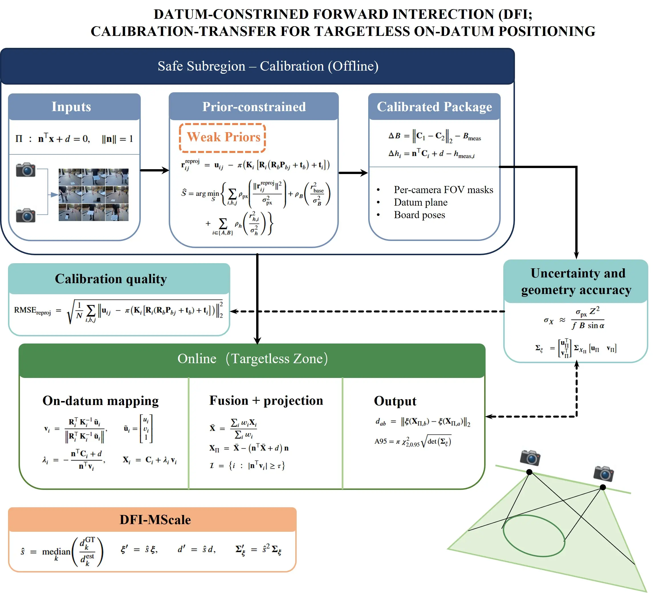
Figure 1. Framework for relative positioning using DFI. DFI: datum-constrained forward intersection.
3.2 Problem setting and site datum
3.2.1 Scene and coordinates
We consider restricted-access built environments in which all cameras are mounted in a reachable safe subregion, while the targetless zone cannot host fiducials or survey control. A world frame W is anchored to a durable site reference (e.g., coping stone, deck datum). The site datum is a physical plane present in the scene (e.g., ground/deck), but its parameters are not assumed known a priori and are estimated from safe-zone data (Section 3.3). We define the physical plane as:
Although Π is a physical plane present in the scene, its parameters (n, d) are unknown and are estimated from safe-zone data (Section 3.3). We denote the estimate by
And the optical center is Ci = -RTi ti. The on-datum 2D coordinates for any x ∈ Π are defined by an orthonormal basis {uΠ, vΠ} that spans and a site mark x0:
The deployment geometry is an explicit design variable: the baseline-to-range B/Z and the inter-ray intersection angle α are constrained during placement (mildly convergent views, non-grazing incidence) to stabilize conditioning and downstream uncertainty. A top-down layout of cameras and ChArUco boards in the safe subregion is shown in Figure 2, making the constraints B/Z and α explicit.
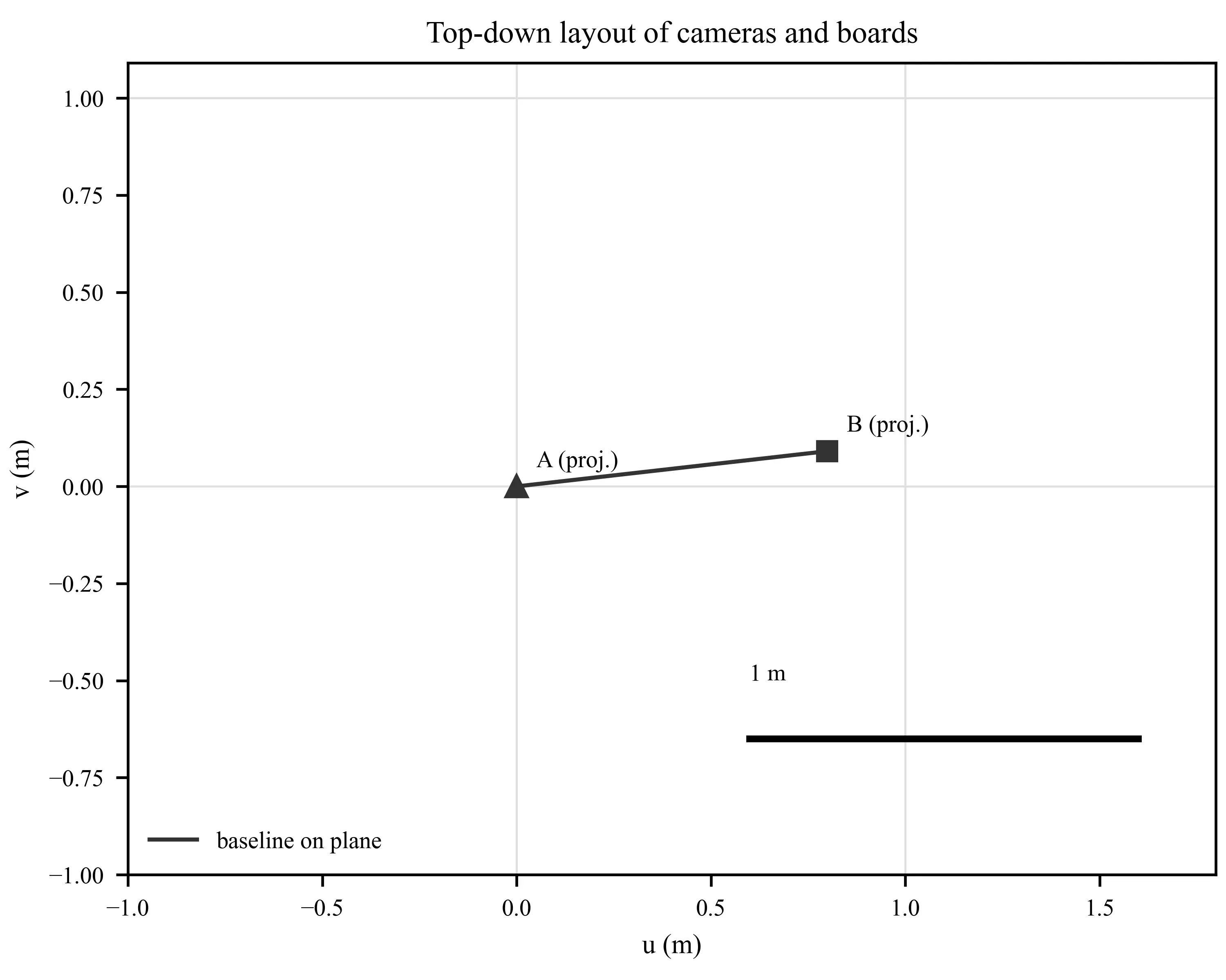
Figure 2 documents the safe-subregion geometry used by the calibration-transfer pipeline and makes the constraints B/Z and α explicit.
3.2.2 Inputs and outputransfer
Inputs: (i) undistorted ChArUco corner detections {uij} with board IDs and the known target geometry {Pbj} (ii) weak but auditable tape measurements (with recorded standard deviations): inter-camera baseline Bmeas ± σB, and optical-centre heights hmeas,i ± σh relative to the site datum plane; (iii) at least one intentionally tilted board to break coplanarity.
Height measurement convention: we model hmeas,i as a noisy observation of the signed distance from the optical-centre to the plane along the plane normal, i.e., hmeas,i ≈ nTCi + d. We orient n from the datum towards the cameras so that hmeas,i > 0, and after estimation we enforce this sign convention by flipping (n, d) ← (-n, -d) if needed. In practice, heights are often recorded using a tape aligned with local gravity; the tolerance therefore absorbs tape reading/placement errors as well as any small mismatch between gravity and the estimated plane normal.
Outputs: (i) camera extrinsics
Given the package above, per-target pixel rays from multiple cameras intersect Π in closed form and are fused by incidence weighting to produce map coordinates ξ and pairwise distances with 95% confidence ellipses (A95). Geometry-to-accuracy guidance links B/Z and α to achievable uncertainty and informs placement under mounting and field-of-view limits.
Eqs. (1)-(3) define the reference system into which all subsequent estimates, distances, and uncertainties are reported. They make the calibration-transfer objective precise: complete metric anchoring in the safe subregion and transfer of scale, pose, and plane uncertainty across the boundary so that on-datum outputs in the targetless zone are quantitatively interpretable and auditable.
3.3 Safe-zone calibration via prior-constrained bundle adjustment
3.3.1 States and measurements
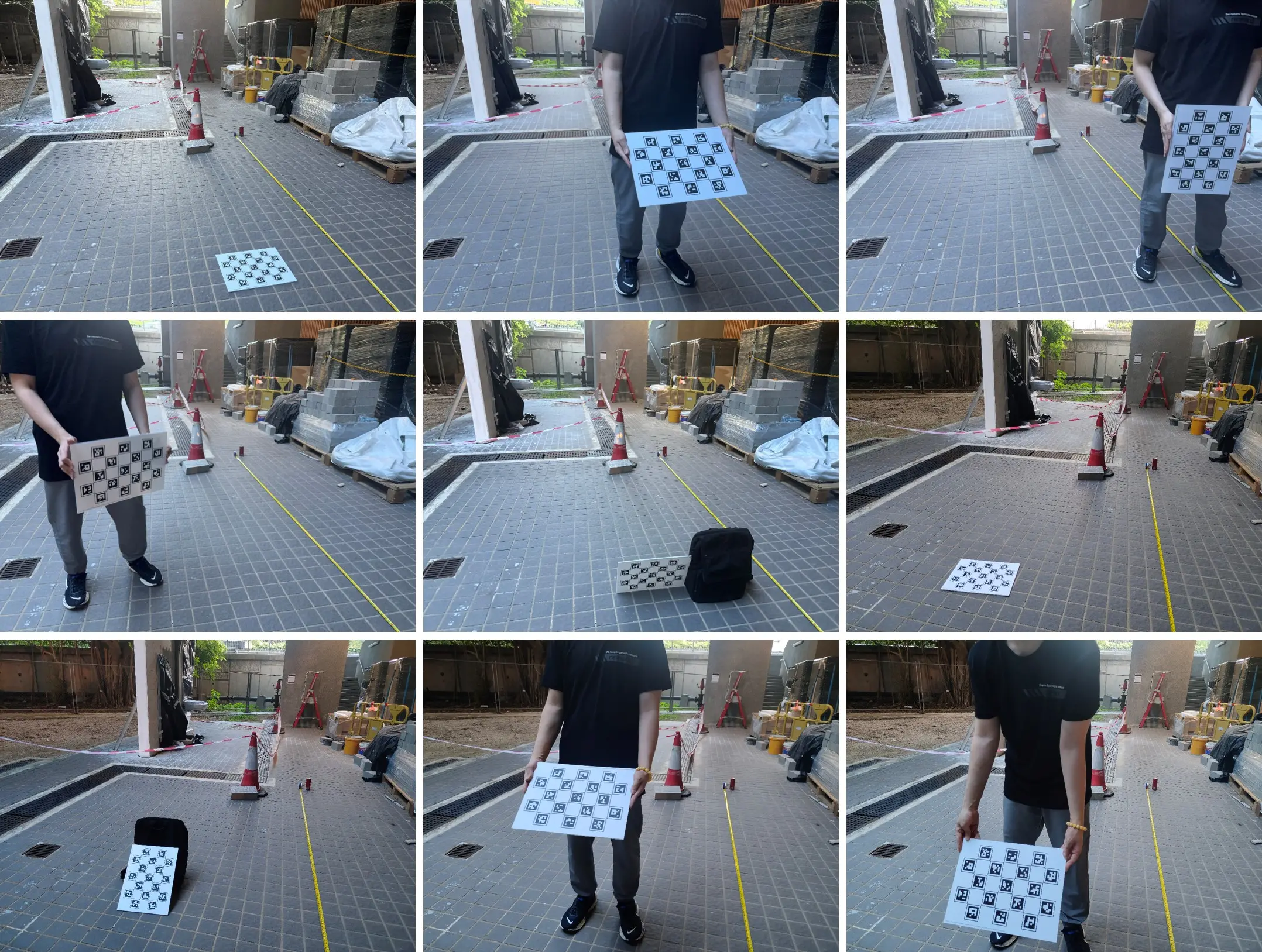
To complete calibration outside inaccessible areas, we captured the ChArUco image shown in Figure 3 within a secure sub-area. We recorded the camera baseline and the height from the optical center to the reference plane using a tape measure, while simultaneously placing an inclined target to break the coplanarity (Figure 3).
The safe-zone calibration estimator jointly recovers camera extrinsics, ChArUco board poses, and the site datum plane from safe-zone imagery while keeping the solution metrically anchored. The state is:
For each ChArUco corner detected uij on the board b in the camera i, the residual undistorted reprojection is:
With pixel noise modeled as zero mean Gaussian of variance
3.3.2 Auditable weak priors
Tape-measured field quantities stabilize the metric solution under modest baselines and mildly convergent views. Optical centers are Ci = -RTiti. The baseline prior to the camera enforces the measured separation Bmeas within its standard deviation σB:
The height priors constrain the optical center distances to the operating plane Π; with the signed distance nTCi + d, the residual for the camera i is:
Weighted by σh from the same tape log. Using distances to Π avoids assumptions about ground levelness or tilt and keeps the anchor aligned with the site datum. At least one intentionally tilted board (~3,045º) is included to break the coplanarity, restoring the observability of depth/scale under safe-zone constraints.
3.3.3 MAP objective and solver schedule
The maximum a posteriori estimate minimizes a robustified, weighted least-squares objective combining reprojection and auditable priors.
Subject to
Eq. (5) extracts all the geometric information available from the ChArUco imagery; Eqs. (6) and (7) inject centimeter-level, auditable anchors that suppress classic degeneracies under modest B/Z and small α. The schedule around Eq. (8) delivers a metrically anchored package whose posterior covariance is subsequently transferred to on-datum coordinates and distances of the datum with actionable A95.
3.4 On-datum localization and uncertainty
3.4.1 Ray–plane mapping with incidence-weighted fusion
Given a target pixel ui observed by camera i, we first undistort and project back to a unit ray in the camera frame, then rotate into W. With Ki and Ri from the safe-zone calibration and optical center Ci = -RTiti, the ray direction in W is:
Intersecting the ray Ci + λvi with the operating plane Π: nTx + d = 0 (Eq. (1)) gives a closed-form range and landing:
In exact arithmetic, each landing Xi in Eq. (10) satisfies nTXi + d = 0, and thus their weighted mean would also lie on Π. We nevertheless apply the orthogonal projection in Eq. (11) to (i) enforce the plane constraint under finite-precision computation, (ii) guard against small cross-view inconsistencies introduced by practical gating/masking or online refinement, and (iii) ensure that subsequent map-coordinate evaluation is performed exactly on Π.
To improve conditioning under mildly convergent views, we fuse multi-view landings using incidence weights
Map-plane coordinates follow Eq. (3), and the pairwise distances between two fused targets a, b are:
Eqs (9)-(12) implement the calibration transfer in the target-zone measurement stage: only closed-form ray– plane geometry is executed during measurement, while metric scale and the datum Π are supplied by the safe-zone calibration. Two guardrails are enforced in practice: (i) an incidence gate |nTvi > τ| (e.g., τ = 0.05) rejects near-grazing rays; (ii) per-camera field-of-view masks from calibration prevent off-plane clutter and partial occlusions from contributing to the fusion. As shown in Figure 4, this visualization connects the closed-form mapping (Eqs. (9)-(11)) to decision-ready on-plane coordinates.
3.4.2 First-order uncertainty propagation and A95
Let θ collect the state blocks whose posteriors are retained from the offline estimator (camera poses and plane parameters required for propagation), with covariance Σθ. For camera i, the landing map Xi = gi(ui, θ) in Eq. (10) has Jacobians Ju,i = ∂gi/∂ui and Ju,i = ∂gi/∂ui∂θ. Assuming per-pixel noise Σu,i = σ2pxI2 after undistortion and small cross-camera correlations in pixels, the per-view landing covariance is:
With the weighted mean in Eq. (11), a first-order fusion covariance is:
In this formula, PΠ = I3 - nnT projects covariances onto Π. Expressed on a local basis {uΠ, vΠ}, the 2 × 2 covariance Σξ produces the 95% confidence ellipse (A95) via the chi-square quantile
Eqs. (13)-(15) turn the pixel noise and the uncertainty of the retained state into a decision-region in the site datum. The ellipse axes and azimuth (from the eigendecomposition of Σξ) accompany ξ and dab (Eq. (12)), so each reported coordinate and distance carries an interpretable uncertainty on Π for inspection and response workflows. Intuitively, A95 can be interpreted as the expected 95% positional footprint on the site datum plane for each reported point.
3.5 Minimal metric self-calibration in the field (DFIMScale)
Minor focus/refocus and resolution changes can leave a residual global similarity (scale) bias after safe-zone calibration, even when {TWi} and are metrically anchored by auditable priors. We correct this bias in situ with a single scale parameter using a small set of tape-measured on-datum distances in the targetless zone. Let {dGTk} denote the pairwise distances measured on the site datum Π using a tape measure, and let {destk}denote the corresponding distances estimated by DFI via Eq. (12) in Section 3.4. A robust scale factor is:
This is consistent with a global similarity drift and resists single-pair outliers. If desired, a least-squares alternative can be used when more pairs are available.
The correction is applied uniformly to all on-datum outputs:
Where Σξ comes from the first-order propagation in Section 3.4.2. The A95 ellipse scales linearly in the axes and quadratically in the area under Eq. (18), preserving the interpretation of uncertainty.
In principle,
3.6 Geometry-to-accuracy guidance for deployment
Under small-angle triangulation and fixed optics, the lateral on-datum standard deviation obeys the well-known scaling.
Where σpx is the per-coordinate pixel noise after undistortion, f is the focal length in pixels, B is the stereo baseline, Z is range to the target, and α is the inter-ray intersection angle. Eq. (19) makes explicit how the conditioning deteriorates for small B/Z or near-parallel views (α→0), and explains the growth of A95 as the geometry weakens.
For seawall/bridge-edge layouts with mounting height and FOV limits, we target B/Z ∈ [0.10,0.25] and α ∈ [10º,30º] to keep σX in the decimeter regime with consumer cameras. These ranges were enforced in our placements and are consistent with the empirical error and A95 we report.
A precomputed heat map of Eq. (19) over (B/Z, α) provides a site-specific planning tool; the current experimental layout is overlaid as a marker to show operating conditions relative to iso-error contours. The heat map is evaluated over B/Z ∈ [0.02,0.30] and α ∈ [1º,40º]; axes are labelled in B/Z (unitless) and α (deg). Figure 5 visualizes Eq. (19) over the deployment design space: the dashed rectangle marks the recommended band (B/Z ∈ [0.10,0.25], α ∈ [10º,30º]), and the red marker indicates the configuration used in this study (B/Z = 0.135 α = 20º).

Figure 5. Geometry-to-accuracy scaling predicted by Eq. (19). Color indicates the predicted on-datum lateral standard deviation σX (mm), and the marker indicates the deployed layout.
Eq. (19) turns the geometry of placement into actionable precision targets, links A95 to controllable field variables, and justifies the recommended bands B/Z and α that our deployment follows.
4. Results and Discussion
4.1 Safe-zone calibration quality and internal consistency
4.1.1 Pre/postBA reprojection accuracy
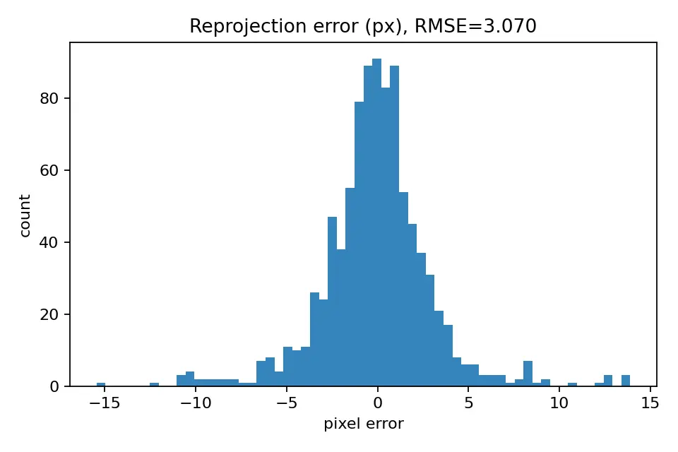
The prior-constrained BA in the safe subregion is evaluated by the root-mean-square reprojection error:
Here N is the number of observed ChArUco corners in the safe subregion. The calibration reduces RMSEreproj from 7.93 px (initialization) to 3.07 px (post-BA), resulting in a decrease of 61%. The post-BA histogram is unimodal with a light positive skew, indicating that most corners are well explained despite reflective backgrounds. This reduction is essential because it certifies that the metric anchor is internally consistent before any cross-boundary transfer. The post-BA residual distribution is shown in Figure 6.
4.1.2 Consistency with auditable priors and datum
Agreement with field-auditable priors is quantified by signed residuals for the baseline and optical-center heights:
And their normalized scores zB = ∆B/σB, zh,i = ∆hi/σh. The posterior baseline is 0.8128 m, compared to the tape prior Bmeas = 0.81 ± 0.008 m, giving ∆B = +0.003=0.003 m and zB = 0.38 (well within 2σ). The recovered plane Π = (n, d) yields optical-center signed distances that are checked against the recorded height priors via ∆hi and the corresponding normalized scores zh,i (with the sign convention enforced as described in Section 3.2.2). The prior-consistency check is visualized in Figure 7.
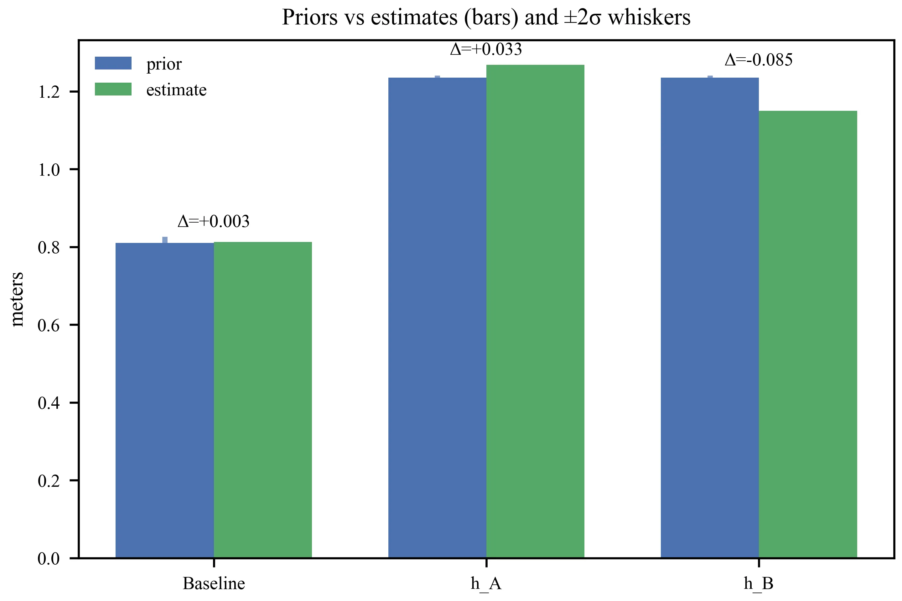
Consistency with auditable priors in the safe subregion. The bars compare the previous estimate (blue) and the posterior estimate (green) for the stereo baseline and the two optical-center heights; blue whiskers indicate ±2σ from tape-measure tolerances. The numeric deltas ∆ annotate the signed differences. These checks demonstrate that the BA solution is metrically anchored by weak and auditable measurements, which is necessary for trustworthy on-datum mapping and subsequent uncertainty propagation.
Eq. (20) certifies image-level fit; Eq. (21) certifies the metric anchoring against field-auditable quantities. Together, they validate the calibration package ({TWi}, Π) used downstream for on-datum ray-plane mapping, incidence-weighted fusion, and A95 reporting in the targetless zone.
4.2 On-datum localization accuracy and uncertainty
Using the calibration package from
To remove a small, scene-specific scale bias while preserving auditability, a single parameter is estimated from the distance ratios (DFI-MScale):
And absolute errors are:
The on-datum evaluation uses three visually distinctive points that (i) are simultaneously visible in both cameras, (ii) admit repeatable manual identification in targetless imagery, and (iii) have tape-measured ground-truth distances recorded on the site datum. This small sample primarily reflects practical constraints in hazard-adjacent environments (limited access time and limited safe placement of reference distances), rather than an attempt to claim population-level statistics. Accordingly, we report the full set of per-pair errors, together with summary statistics (median, maximum), and interpret p90 as a tail indicator for comparability rather than a stable quantile under large N.
Because only three pairwise distances are available from the three clicked points (P1–P3), we additionally report the per-pair scale ratios
With pairs of N = 3, we summarize the precision by the median and the 90th percentile (p90) of {ek} and assess the agreement with a Bland-Altman analysis (mean bias and limits of agreement).
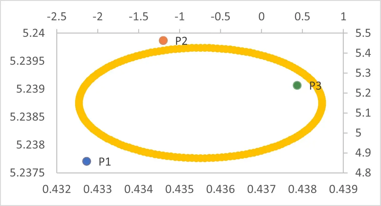
For each fused landing, the planar covariance ΣX is obtained by first-order propagation of the pixel noise and the offline covariance blocks. The confidence ellipse 95% (A95) in Π uses the chi-square quantile for 2D:
These ellipses communicate decision-ready uncertainty together with the reported coordinates and distances. Before applying DFI–MScale, the raw on-datum distance estimates exhibit a consistent global scale bias (median ratio
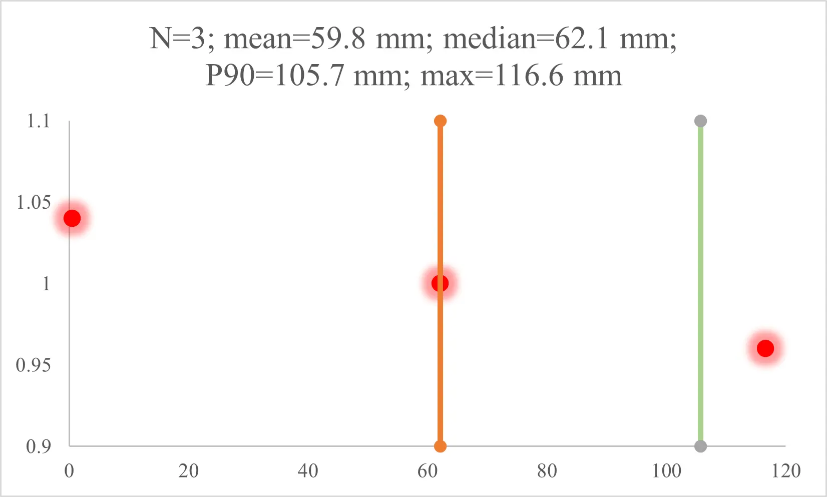
After applying the one-parameter scale correction (DFI–MScale) according to Eq. (23), the absolute distance errors (mm) reduce to: median = 62.1, p90 = 105.7 mm, max = 116.6 mm, and mean = 59.8 with N = 3. The Bland–Altman bias is -18.3 mm, and the limits of agreement are [-196.1, 159.4] mm, indicating a small average bias after the single-parameter correction and a spread consistent with the A95 footprints observed in Π.
Eqs. (22)-(25) instantiate the DFI deployment-facing contract: on the same images and without in-zone fiducials, the pipeline outputs on-datum coordinates, pairwise distances, and an explicit A95 per landing; a one-shot metric self-calibration (
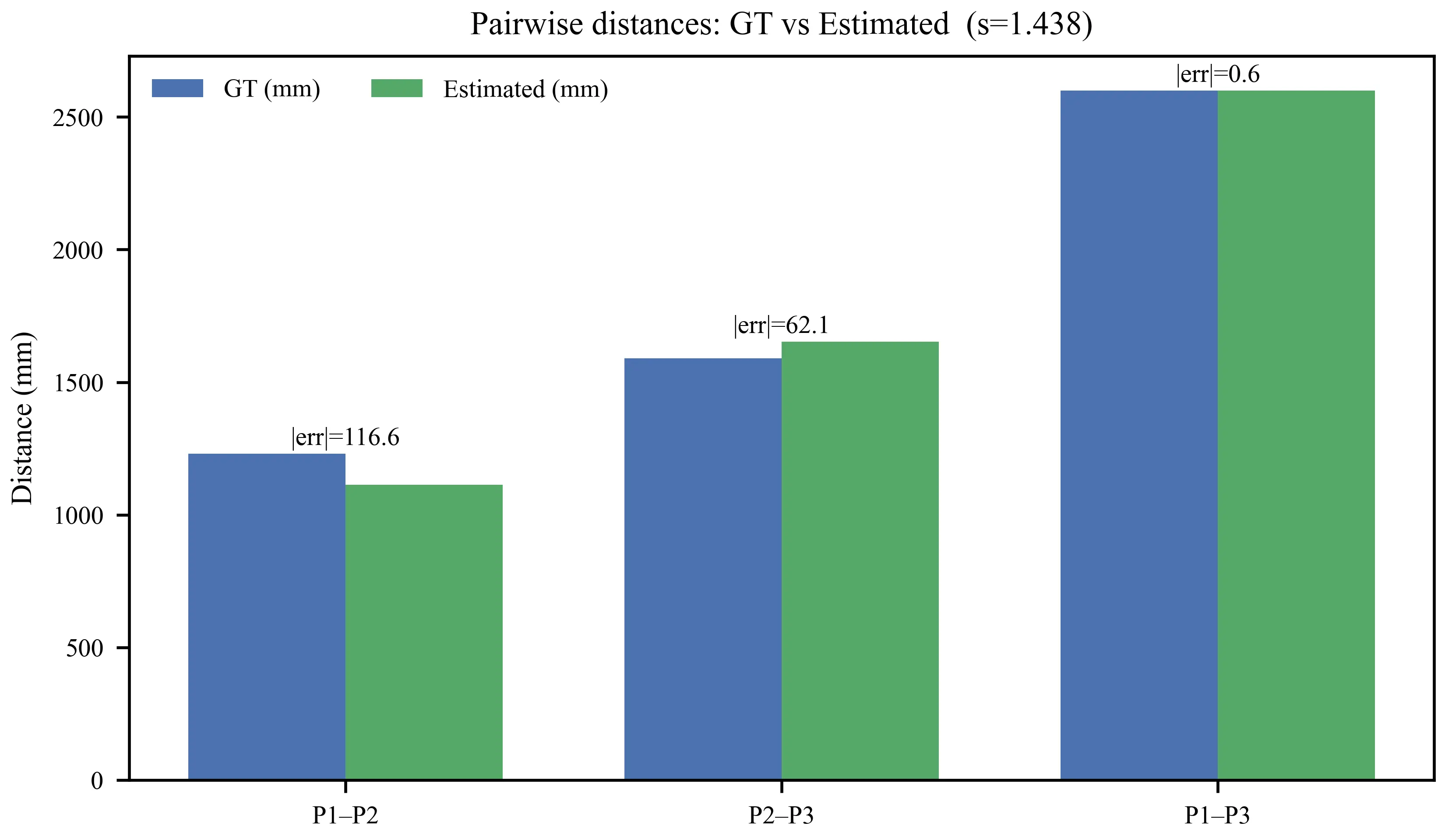
The distribution of absolute distance errors is shown in Figure 9. Agreement between estimated and tape-measured distances is further examined using a Bland–Altman plot (Figure 10).
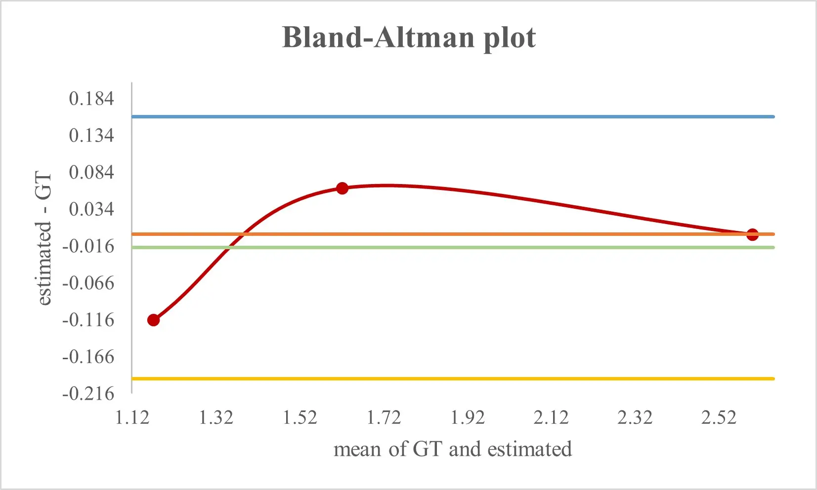
Given the limited number of distance pairs N = 3), we do not treat p90 as a statistically stable quantile, nor do we claim empirical coverage validation of the 95% confidence ellipse. Instead, we report A95 as a model-based uncertainty region obtained by first-order propagation, and we include a simple leave-one-out sensitivity check for the scale factor. Specifically, estimating from two of the three ratios and evaluating the held-out pair yields absolute errors of approximately 0.137 m (P1–P2 held out), 0.149 m (P2–P3 held out), and 0.087 m (P1–P3 held out). This check suggests that, under operator-dependent clicking and short-distance tape measurements, the inferred global scale can vary non-negligibly with the chosen point pairs, which further motivates reporting per-pair residuals alongside summary statistics.
4.3 Comparison with two-view baselines on the same images
This experiment tests whether the DFI delivers lower on-datum distance error than recent two-view pipelines when all methods are evaluated on the same image pair and intrinsics. The protocol is identical across baselines to isolate the effect of geometry and estimation rather than data differences.
Feature matching uses official implementations: ORB, LoFTR, LightGlue, and RoMa. The matches are undistorted and normalized by KA, KB. The essential matrix E is estimated with USAC-MASAC, followed by pose recovery {R, t}. The translation is scaled to the tape-measured baseline:
Ensure a metric triangulation. The same three manually clicked target points (P1-P3),
And converted into pairwise distances.
The absolute errors w.r.t. ground truth are
DFI with s = 1.438 attains median = 62 mm and p90 = 106 mm. Two-view baselines on the same images, intrinsics, and three points yield the following. ORB 628/924, mm, LoFTR 534/858, mm and RoMa 341/491, mm (median/p90). LightGlue did not produce a stable pose on this pair under the inlier gate (weak texture and small parallax); its numbers are omitted from the bar chart, but the run is documented in the benchmark logs. Figure 11 highlights that, with modest B/Z and mild convergence, DFI reduces p90 by 88.5% vs. ORB, 87.6% vs. LoFTR, and 78.4% vs. RoMa. These empirical gains are consistent with prior analyses of two-view geometry and dense matching[7-10,19-21]. Classical pipelines that estimate an essential matrix from correspondences tend to become unstable when the baseline-to-range ratio and the inter-ray angle are small, and learning-based matchers primarily improve appearance robustness rather than the underlying geometric conditioning. By contrast, DFI avoids repeatedly estimating an ill-conditioned essential matrix on weak-baseline pairs and instead reuses a well-constrained multi-camera calibration from the safe subregion. This design choice explains why DFI maintains decimetre-level accuracy where ORB, LoFTR, and RoMa degrade to errors of several tens of centimetres to nearly a metre on exactly the same imagery. Importantly, DFI is complementary to learned matchers: such matchers can be integrated upstream to automate robust pixel-ray extraction or target point selection, while DFI provides the datum-anchored metric transfer and uncertainty reporting that two-view pipelines do not target.
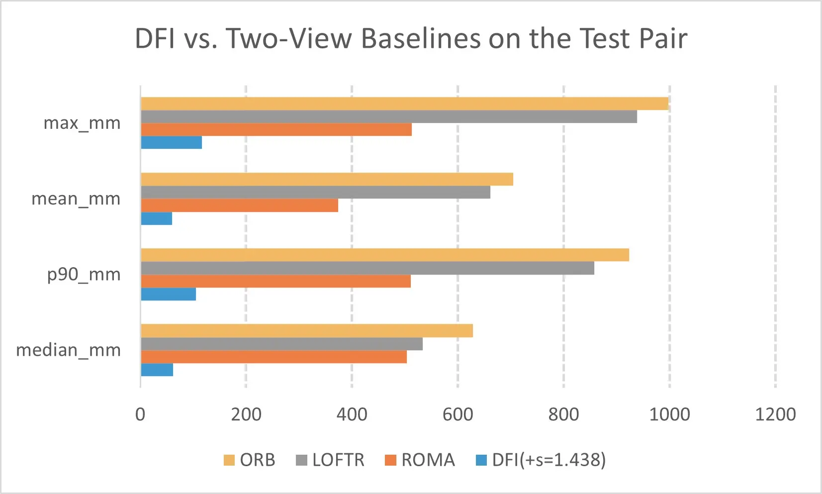
Figure 11. Two-view baselines on the test pair. Error values are reported in mm. All methods use the same image pair, the same intrinsics, and the same clicked target points.
As shown in Figure 11, DFI achieves substantially lower on-datum distance errors than two-view baselines on the same image pair, using identical intrinsics and the same clicked target points. All methods use the same intrinsics and three targets. DFI operates on the datum with incidence-weighted fusion and an optional single-parameter scale ?? learned from a few distances.
When B/Z and the inter-ray angle α are modest, the E-based pose is sensitive to mismatches and forward-motion degeneracy; errors then grow with the conditioning predicted by
4.4 Practical insights from geometry and uncertainty
The goal is to turn calibrated geometry into actionable accuracy control for on-datum positioning. The analysis connects baseline-to-range B/Z and the inter-ray angle α with the observed A95 ellipses and distance errors, and it justifies the gating used by the online fusion.
4.4.1 Analytical scaling and what it predicts
Keeping optics and pixel noise fixed, the lateral standard deviation on the datum scales with geometry as:
Where σpx is the per-coordinate pixel noise after undistortion, f is the focal length in pixels, Z is the standoff to the target, B is the stereo baseline, and α is the angle between viewing rays at the landing. When B/Z or α is small, (29) predicts rapid growth of both the A95 area and the pairwise distance error.
4.4.2 What the data show and how it guides deployment
The experimental layout (baseline ≈0.81 m, mildly convergent views) falls within the well-conditioned band in the heatmap, and the fused on-datum outputs reflect this conditioning. After the single-parameter metric self-calibration (s = 1.438), the on-datum pairwise distances achieve median = 62 mm and p90 = 106 mm. The same geometry explains the behavior of two-view baselines evaluated on identical images: methods that rely on essential-matrix recovery degrade sharply when α is modest and B/Z is small, which is consistent with (29). In contrast, the proposed fusion operates directly on Π and reports A95, so the uncertainty remains auditable even when the texture is weak and the views are only mildly convergent.
4.4.3 Gating, fusion, and uncertainty that survive field conditions
Near-grazing incidence is ill-conditioned. The online stage therefore excludes rays with weak support and fuses only informative views:
With τ = 0.05 in our runs. The fused point is orthogonally projected back to Π, and first-order propagation yields the planar covariance that defines A95. The scale update is linear: if a one-shot metric correction is applied to translation, the on-datum coordinates and their standard deviations in meters scale by as well, so the A95 areas scale by s2; this preserves auditability and communicates residual uncertainty honestly.
4.4.4 Operator variability of tape priors and stability of DFI–MScale
Tape-measured priors (baseline and optical-centre heights) are deliberately chosen because they are auditable and low-cost, but they are also operator-dependent. In our formulation, this variability is represented explicitly by σB and σh in the MAP objective (Eq. (8)) and is carried forward to the datum via first-order propagation (Eqs. (13)-(15)). In practical terms, residual scale uncertainty induced by baseline/height measurement uncertainty directly inflates on-datum coordinates and A95: the A95 axes scale approximately linearly with the global scale factor, and the A95 area scales approximately quadratically.
Given the limited number of taped distances and target pairs in this study (N = 3), we do not treat quantiles such as p90 as statistically stable, nor do we attempt to validate uncertainty coverage empirically. Instead, we report all per-pair residuals and include a leave-one-out check for the scale factor in Section 4.2, which directly reflects sensitivity under the actual field images and tape measurements.
4.4.5 Operational guidance distilled from analysis and data
For clarity and reproducibility, we summarize the key deployment guidelines supported by Eq. (29) and the observed A95/distances in the following boxed summary.
Summary of deployment guidelines.
• Keep B/Z in the ≈ 0.10-0.25 band and α in the ≈10º-30º band whenever mounting and FOV allow; this keeps sin away from zero and limits A95 growth.
• Enforce the incidence gate in (30) and honor per-camera FOV masks; exclude landings driven by grazing rays or outside the validated sectors.
• Use at least one tilted board during safe-zone calibration to break coplanarity; this stabilizes depth/scale and makes the Π posterior covariance meaningful for propagation.
• Apply the minimalist scale update s when a residual global scale bias is observed in the target zone; report the post-scale distances together with the correspondingly scaled uncertainty.
Geometry is a controllable resource. By designing B/Z and α in a well-conditioned band, gating away near-grazing views, and reporting A95 after a transparent one-parameter scale correction, the pipeline delivers on-datum accuracy that is both competitive and auditable under restricted-access constraints. For instance, in hazard-adjacent inspection scenarios such as seawalls, quay walls, bridge edges, bridge bearings, and temporary works, a practitioner can use a tape or laser rangefinder to (i) ensure that neighboring cameras achieve an appropriate baseline relative to the expected standoff, and (ii) verify that the resulting intersection angle remains within the recommended range. Together with a small set of taped on-datum distances for estimating the DFI–MScale factor, these steps support traceable on-datum measurements without installing control points in the targetless zone.
For context, survey-grade instruments such as total stations can deliver millimetre-level 3D coordinates but typically require a line-of-sight workflow and the placement of a prism/target and/or control near the zone of interest, which may be infeasible in hazard-adjacent or fenced areas. Laser rangefinders provide accurate one-dimensional distances but do not directly yield plane-referenced 2D coordinates or uncertainty regions without additional geometric constraints. DFI occupies a complementary middle ground: it supports targetless, cross-boundary operation and reports on-datum coordinates with A95, while still allowing stronger external measurements (e.g., a few taped or rangefinder distances) to be incorporated transparently as priors or as DFI–MScale inputs when available.
5. Conclusions
This study proposes and validates a DFI pipeline that completes all metric calibration in a reachable safe subregion and delivers on-datum positions, pairwise distances, and reportable uncertainty in targetless GNSS-degraded environments. The main findings are summarized below:
• We formulate a calibration-transfer pipeline that completes all metric calibration in a reachable safe subregion and transfers scale, pose, and a site-meaningful datum across the boundary to a targetless zone. A prior-constrained bundle adjustment jointly estimates multi-camera extrinsics and the datum plane using only tape-measured baseline and optical-center heights plus a single tilted target to break coplanarity; the solution stays metrically anchored without any in-zone fiducials or GNSS.
• We develop a run-time refinement that parameterizes small similarity left multipliers on intrinsics and optimizes them jointly with pose under strong regularization from the safe-zone posterior, absorbing minor refocus/zoom and mixed resolutions while preserving geometric consistency, thus removing the need for rigid fixed-focus optics in the field.
• Field robustness and same-image benchmarking are demonstrated by a BA-anchored online refinement that absorbs modest refocus/zoom and mixed resolutions, and by a minimalist in situ scaling step (DFI–MScale) that estimates a single factor from a few taped distances (in our test pair, s = 1.438). In the same images, intrinsics and three targets, the pipeline achieves a median of 62 mm and a p90 distance error of 106 mm on the site datum, reducing p90 by 88.5% versus ORB (924 mm), 87.6% versus LoFTR (858 mm), and 78.4% versus RoMa (491 mm), with the largest gains in the tail that matter for decision readiness.
A practical limitation is that the evaluation does not include extreme illumination and seasonal changes of a long duration. Future work will extend the formulation to time-varying or piecewise-planar datums and incorporate lightweight inertial cues to further strengthen long-horizon uncertainty reporting.
Supplementary materials
The supplementary material for this article is available at: Supplementary materials.
Acknowledgments
ChatGPT (version 5.2) was used to assist with language polishing of the manuscript. The authors take full responsibility for the final content of the article.
Authors contribution
Yang Y: Methodology, formal analysis, writing-original draft.
Guo W: Investigation, data curation.
Xu G, Qu C, Hou L: Writing-review & editing.
Li H: Supervision, project administration.
Chen H: Visualization.
Zhang G: Conceptualization, methodology, writing-review & editing.
Conflicts of interest
The authors declare no conflict of interest.
Ethical approval
Not applicable.
Consent to participate
Not applicable.
Consent for publication
Not applicable.
Availability of data and materials
The data and materials could be obtained from the corresponding author upon request.
Funding
This work was supported by the RISUD Interdisciplinary Research Scheme (Grant No. A/C: 1-BBWV).
Copyright
©The Author(s) 2026.
References
-
1. Bhamidipati S, Kousik S, Gao G. Set-valued shadow matching using zonotopes for 3D-map-aided GNSS localization. J Inst Navig. 2022;69(4):navi.547.[DOI]
-
2. Neamati D, Bhamidipati S, Gao G. Risk-aware autonomous localization in harsh urban environments with mosaic zonotope shadow matching. Artif Intell. 2023;324:104000.[DOI]
-
3. Kim S, Seo J. Performance analysis of zonotope shadow matching algorithm according to various urban environments. J Position Navig Timing. 2024;13(3):215-220.[DOI]
-
4. Peng D, Lin YN, Lee JC, Su HH, Hill EM. Multi-constellation GNSS interferometric reflectometry for tidal analysis: Mitigations for K1 and K2 biases due to GPS geometrical errors. J Geod. 2024;98(1):5.[DOI]
-
5. Theiner J, Ewerth R. TVCalib: Camera calibration for sports field registration in soccer. In: 2023 IEEE/CVF winter conference on applications of computer vision (WACV); 2023 Jan 2-7; Waikoloa, USA. Piscataway: IEEE; 2023. p. 1166-1175.[DOI]
-
6. Li Y, Zhao Z, Chen Y, Zhang X, Tian R. Automatic roadside camera calibration with transformers. Sensors. 2023;23(23):9527.[DOI]
-
7. Sun J, Shen Z, Wang Y, Bao H, Zhou X. LoFTR: Detector-free local feature matching with transformers. In: 2021 IEEE/CVF conference on computer vision and pattern recognition (CVPR); 2021 Jun 20-25; Nashville, USA. Piscataway: IEEE; 2021. p. 8918-8927.[DOI]
-
8. Lindenberger P, Sarlin PE, Pollefeys M. LightGlue: Local feature matching at light speed. In: 2023 IEEE/CVF international conference on computer vision (ICCV); 2023 Oct 1-6; Paris, France. Piscataway: IEEE; 2023. p. 17581-17592.[DOI]
-
9. Edstedt J, Sun Q, Bökman G, Wadenbäck M, Felsberg M. RoMa: Robust dense feature matching. In: 2024 IEEE/CVF conference on computer vision and pattern recognition (CVPR); 2024 Jun 16-22; Seattle, USA. Piscataway: IEEE; 2024. p. 19790-19800.[DOI]
-
10. Sha O, Zhang H, Bai J, Zhang Y, Yang J. The analysis of the structural parameter influences on measurement errors in a binocular 3D reconstruction system: A portable 3D system. PeerJ Comput Sci. 2023;9:e1610.[DOI]
-
11. Zhang J, Sui W, Zhang Q, Chen T, Yang C. Towards accurate ground plane normal estimation from ego-motion. Sensors. 2022;22(23):9375.[DOI]
-
12. Hu J, Yi D, Bisnath S. A comprehensive analysis of smartphone GNSS range errors in realistic environments. Sensors. 2023;23(3):1631.[DOI]
-
13. Yang D, Feng W, Huang D, Li J. Improved global navigation satellite system–multipath reflectometry (GNSS-MR) tide variation monitoring using variational mode decomposition enhancement. Remote Sens. 2023;15(17):4331.[DOI]
-
14. KimS, Seo J. Set-based position ambiguity reduction method for zonotope shadow matching in urban areas using estimated multipath errors. arXiv:2502.11283 [Preprint]. 2025.[DOI]
-
15. Bozorgzadeh A, Umar T. Automated progress measurement using computer vision technology in UK construction. Proc Inst Civ Eng Smart Infrastruct Constr. 2023;176(4):165-182.[DOI]
-
16. Arshad S, Akinade O, Bello S, Bilal M. Computer vision and IoT research landscape for health and safety management on construction sites. J Build Eng. 2023;76:107049.[DOI]
-
17. Pal A, Lin JJ, Hsieh SH, Golparvar-Fard M. Automated vision-based construction progress monitoring in built environment through digital twin. Dev Built Environ. 2023;16:100247.[DOI]
-
18. Barroso-Laguna A, Brachmann E, Prisacariu VA, Brostow G, Turmukhambetov D. Two-view geometry scoring without correspondences. In: 2023 IEEE/CVF conference on computer vision and pattern recognition (CVPR); 2023 Jun 17-24; Vancouver, Canada. Piscataway: IEEE; 2023. p. 8979-8989.[DOI]
-
19. Astermark J, Heyden A, Larsson V. Dense match summarization for faster two-view estimation. In: 2025 IEEE/CVF conference on computer vision and pattern recognition (CVPR); 2025 Jun 10-17; Nashville, USA. Piscataway: IEEE; 2025. p. 1093-1102.[DOI]
-
20. Leroy V, Cabon Y, Revaud J. Grounding image matching in 3D with MASt3R. In: Leonardis A, Ricci E, Roth S, Russakovsky O, Sattler T, Varol G, editors. Computer Vision – ECCV 2024; 2024 Sep 29-Oct 4; Milan, Italy. Cham: Springer.[DOI]
-
21. Wang S, Leroy V, Cabon Y, Chidlovskii B, Revaud J. DUSt3R: Geometric 3D vision made easy. In: 2024 IEEE/CVF conference on computer vision and pattern recognition (CVPR); 2024 Jun 16-22; Seattle, USA. Piscataway: IEEE; 2024. p. 20697-20709.[DOI]
-
22. Dowrick T, Xiao G, Nikitichev D, Dursun E, van Berkel N, Allam M, et al. Evaluation of a calibration rig for stereo laparoscopes. Med Phys. 2023;50(5):2695-2704.[DOI]
-
23. Kusari A, Almutairi AA, Gilbert ME, LeBlanc DJ. Object-level footprint uncertainty quantification in infrastructure-based sensing. IEEE Sens J. 2024;24(8):12539-12549.[DOI]
-
24. Liu Z, Liu X, Zhang F. Efficient and consistent bundle adjustment on lidar point clouds. IEEE Trans Robot. 2023;39(6):4366-4386.[DOI]
-
25. Tang H, Zhang T, Wang L, Yuan M, Niu X. BA-LINS: A frame-to-frame bundle adjustment for LiDAR-inertial navigation. IEEE Trans Intell Transport Syst. 2025;26(5):6621-6634.[DOI]
-
26. Chui J, Cremers D. ProBA: Probabilistic bundle adjustment with the bhattacharyya coefficient. arXiv:2505.20858 [Preprint]. 2025.[DOI]
-
27. Abbas N, Umar T, Salih R, Akbar M, Hussain Z, Xiong H. Structural health monitoring of underground metro tunnel by identifying damage using ANN deep learning auto-encoder. Appl Sci. 2023;13(3):1332.[DOI]
-
28. Zia A, Pu Z, Holly I, Umar T, Tariq MAUR. Development of an analytical model for the FRP retrofitted deficient interior reinforced concrete beam-column joints. Appl Sci. 2022;12(5):2339.[DOI]
Copyright
© The Author(s) 2026. This is an Open Access article licensed under a Creative Commons Attribution 4.0 International License (https://creativecommons.org/licenses/by/4.0/), which permits unrestricted use, sharing, adaptation, distribution and reproduction in any medium or format, for any purpose, even commercially, as long as you give appropriate credit to the original author(s) and the source, provide a link to the Creative Commons license, and indicate if changes were made.
Publisher’s Note
Science Exploration remains a neutral stance on jurisdictional claims in published
maps
and institutional affiliations. The views expressed in this article are solely those
of
the author(s) and do not reflect the opinions of the Editors or the publisher.
Share And Cite


Science Exploration Style
Yang Y, Xu G, Qu C, Li H, Chen H, Hou L, et al. Vision-based relative positioning in targetless environments via datumconstrained forward intersection. J Build Des Environ. 2026;4:2025100. https://doi.org/10.70401/jbde.2026.0028
Tips
Copy completed.
Submit a Manuscript
Author Instructions
Cite this Article
Article Metrics
0
View
0
Download
Cited
Article Updates

- Abstract
- Keywords
- 1. Introduction
- 2. Literature Review
- 3. Methodology
- 4. Results and Discussion
- 5. Conclusions
- Supplementary materials
- Acknowledgments
- Authors contribution
- Conflicts of interest
- Ethical approval
- Consent to participate
- Consent for publication
- Availability of data and materials
- Funding
- Copyright
Science Exploration Style
Yang Y, Xu G, Qu C, Li H, Chen H, Hou L, et al. Vision-based relative positioning in targetless environments via datumconstrained forward intersection. J Build Des Environ. 2026;4:2025100. https://doi.org/10.70401/jbde.2026.0028
copy
Share Link
copy